Posted on

Analysis and Solutions for ERR10 Fault in CANWORLD CDE300 Series Inverter

Introduction

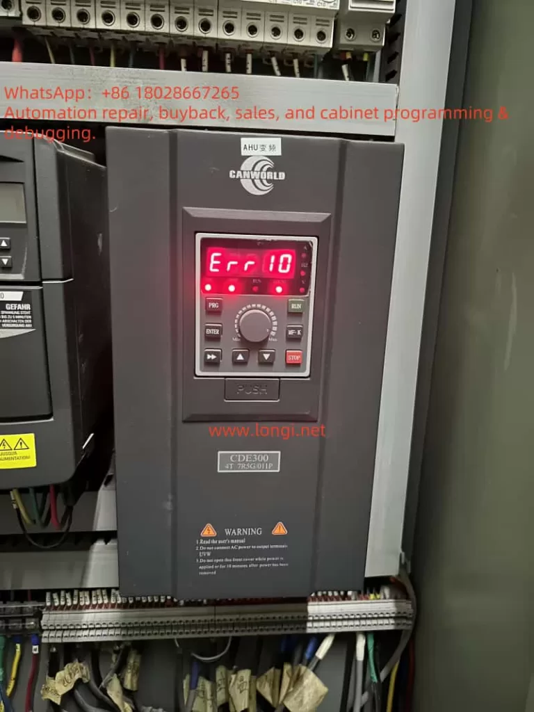
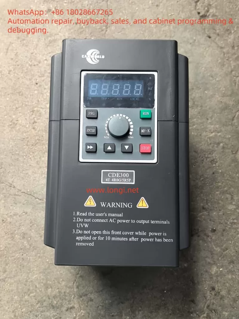
The CANWORLD CDE300 series inverter is a high-performance variable frequency drive (VFD) designed for three-phase motor control, widely used in industrial automation. Its primary functions include adjusting motor speed, improving energy efficiency, and ensuring smooth equipment operation. However, in practical applications, inverters may encounter faults due to various reasons. Among these, the ERR10 fault—indicating module overheating—is a common alarm that requires prompt attention to prevent equipment damage or downtime.

This article is based on the “CDE300 CANWORLD Three-Phase User Manual V1.10.pdf” and the provided fault screenshot. It provides an in-depth discussion of the ERR10 fault, including its meaning, potential causes, troubleshooting steps, and preventive measures. Through a clear structure and logical analysis, this article aims to offer practical guidance to help users quickly resolve module overheating issues and ensure long-term stable operation of the equipment.

ERR10

Meaning of ERR10 Fault

The ERR10 fault in the CANWORLD CDE300 series inverter specifically indicates “module overheating.” The power module of the inverter, typically composed of core components such as Insulated Gate Bipolar Transistors (IGBTs), is responsible for converting the input power into the appropriate output voltage and frequency for motor operation. During operation, these components generate significant heat due to energy losses. To protect the equipment, the inverter is equipped with temperature sensors that monitor the power module’s temperature in real time. When the temperature exceeds a safe threshold, the system triggers the ERR10 fault alarm and may automatically shut down to prevent further thermal damage.

The consequences of module overheating should not be underestimated. Prolonged high temperatures can lead to IGBT aging, performance degradation, and even permanent damage to the power module. Therefore, accurately understanding the ERR10 fault and taking effective measures are crucial.

Possible Causes of ERR10 Fault

Module overheating is usually caused by a combination of factors. Based on the design features of the CDE300 series inverter, the user manual, and common issues in industrial applications, the following are the main potential causes of the ERR10 fault:

  1. High Ambient Temperature
    According to the “Installation Site” section in Chapter 3 (PAGE22) of the user manual, the operating ambient temperature for the CDE300 series inverter should typically be between -10°C and 40°C. If the installation environment exceeds this range, the inverter’s cooling system may be unable to effectively reduce the module temperature, triggering the ERR10 fault.
  2. Poor Ventilation
    The inverter requires adequate airflow for heat dissipation. The manual mentions the need for sufficient space around the inverter during installation (PAGE13, Section 2.5.1 “Product Installation Dimensions”). If the installation location is too confined or near other heat sources, heat accumulation may occur, affecting cooling efficiency.
  3. Cooling System Failure or Blockage
    The CDE300 series inverter relies on built-in fans and heat sinks for thermal management. If the fan stops working, operates at reduced speed, or if the heat sink is clogged with dust or grease, cooling efficiency will significantly decrease. This is particularly common in industrial environments where the air may contain a high concentration of particulates.
  4. Overloaded Condition
    When the load driven by the inverter exceeds its rated capacity, the power module will bear higher current and thermal stress. The manual’s Section 2.3 “CDE300 Series Inverter Models” (PAGE9) lists the rated power for each model, such as CDE300-4T7R5G/011P. If the actual load exceeds the specifications, it may lead to module overheating.
  5. Wiring Issues
    Incorrect electrical installation (such as loose or poor connections) can increase resistance, generating additional heat. Section 3.2 “Electrical Installation” (PAGE25) and the “Main Contents of the Distribution Room” on PAGE30 emphasize the importance of proper wiring and grounding. Wiring errors may indirectly cause the ERR10 fault.
  6. High Switching Frequency
    A higher switching frequency in IGBTs results in increased heat generation. If the switching frequency is set too high in the inverter’s parameters, it may exacerbate the thermal load on the module, leading to overheating.
  7. Hardware Failure
    If all external factors are normal, the issue may lie with the power module or temperature sensor itself, such as a damaged IGBT or a malfunctioning sensor reporting false high temperatures.
CDE300

Troubleshooting and Solutions for ERR10 Fault

To resolve the ERR10 fault and restore the inverter to normal operation, users can follow these step-by-step troubleshooting procedures:

1. Power Off and Cool Down the Equipment

Upon detecting the ERR10 fault, immediately turn off the inverter’s power and allow the equipment to cool naturally. The “Safety Markings” section in Chapter 1.1 (PAGE4) recommends waiting at least 10 minutes after powering off to ensure internal components have cooled and to avoid safety risks.

2. Check Ambient Temperature

Use a thermometer to measure the temperature around the inverter, ensuring it is within the -10°C to 40°C range. If the temperature is too high, improve environmental conditions by adding ventilation equipment (such as fans or air conditioning) or relocating the inverter.

3. Assess Ventilation and Installation

Refer to Section 2.5 “Product Type Diagram and Installation Hole Dimensions” (PAGE11-13) in the manual to check if there is sufficient space around the inverter (e.g., clearances in front, back, left, and right). Remove any objects that may obstruct airflow and ensure the inverter is not near other heat sources.

4. Clean the Cooling System

Inspect whether the fan is operating normally and clean any dust or debris from the fan blades and heat sink. Use compressed air or a soft brush for cleaning to ensure unobstructed airflow. If the fan is faulty, test its electrical connections and consider replacement.

5. Verify Load Matching

Check if the load parameters match the inverter’s rated capacity (see PAGE9). If the load is too high, reduce the operating load or upgrade to a higher power model. Additionally, inspect the motor for abnormalities (such as short circuits or mechanical jams) that could cause excessive current.

6. Inspect Electrical Connections

Follow the requirements in Section 3.2 “Electrical Installation” (PAGE25) to check the main circuit connections (R, S, T, U, V, W) and grounding (P, P+, P-) for secure and intact connections without looseness or aging. Ensure the input voltage is within the specified range to avoid overcurrent.

7. Adjust Switching Frequency

Using the keypad operation (Chapter 4, PAGE37), access the parameter settings interface to check and reduce the switching frequency (if the application allows). This can decrease the heat generated by the IGBTs, but be cautious not to affect motor performance.

8. Monitor Operation and Test

After completing the above adjustments, restart the inverter and observe its operating status. If the equipment provides temperature display functionality, monitor the module temperature in real time. If the ERR10 fault persists, it may indicate a hardware issue, and it is recommended to contact CANWORLD technical support for further inspection.

Preventive Measures for ERR10 Fault

To prevent the recurrence of the ERR10 fault, users can implement the following preventive measures:

  1. Regular Maintenance
    Conduct a comprehensive inspection of the inverter every 3-6 months, cleaning the fan and heat sink to ensure the cooling system functions properly. In industrial environments, maintenance intervals may need to be shortened.
  2. Optimize Installation Environment
    Choose a well-ventilated installation location away from heat sources, avoiding direct sunlight or high-temperature areas, in accordance with Section 3.1 of the manual.
  3. Proper Load Management
    Monitor load conditions in real time to avoid prolonged overload operation. Utilize the inverter’s built-in diagnostic functions or external devices to track current and temperature.
  4. Parameter Optimization
    Adjust operating parameters based on actual application needs, such as switching frequency and acceleration/deceleration times, to minimize unnecessary heat generation.
  5. Personnel Training
    Train operators to familiarize them with the safety and installation guidelines in the manual and to equip them with basic troubleshooting skills.
  6. Enhanced Cooling Measures
    In high-temperature environments, install additional external fans or air conditioning to further improve heat dissipation.

Conclusion

The ERR10 fault (module overheating) in the CANWORLD CDE300 series inverter is a critical protective alarm that may be triggered by high ambient temperatures, poor ventilation, cooling system failures, overloaded conditions, wiring issues, or hardware malfunctions. Through systematic troubleshooting—from checking the environment to adjusting parameters and performing maintenance—users can typically identify and resolve the issue quickly. Additionally, by implementing regular maintenance and optimizing the operating environment, the likelihood of ERR10 faults can be significantly reduced.

The CDE300 series inverter is renowned for its reliability, but its performance depends on proper installation and maintenance. By following the guidelines in the user manual and the solutions and preventive suggestions provided in this article, users can not only address current module overheating issues but also enhance the overall lifespan and efficiency of the equipment, ensuring stability and safety in industrial applications. For complex issues, it is advisable to contact CANWORLD’s official technical support for professional assistance.

Posted on

Panasonic VF200 Series Inverter “CPU” Fault and ALARM Light Resolution Guide

1. Introduction

The Panasonic VF200 series inverter is a widely used device in industrial automation, known for its efficiency, reliability, and versatility. This series supports single-phase 200V (0.2kW to 2.2kW) and three-phase 400V (0.75kW to 15kW) power supplies, making it suitable for various motor control applications. However, users may encounter issues during operation, one of the most common and troubling being the “CPU” fault code displayed on the inverter’s screen accompanied by the ALARM light. This fault indicates an abnormality in the inverter’s core control system, potentially causing the device to stop functioning and disrupting production efficiency. This article will provide a detailed analysis of the “CPU” fault, its possible causes, and a systematic approach to troubleshooting and resolving the issue to help users quickly restore normal operation.

CPU ALARM

2. Meaning of the “CPU” Fault

In the Panasonic VF200 series inverter, when the display shows the “CPU” fault code and the ALARM light is on, it typically indicates a problem with the inverter’s Central Processing Unit (CPU). The CPU is the “brain” of the inverter, responsible for executing control algorithms, processing input and output signals, and coordinating the overall operation of the device. When the CPU detects an abnormality in itself or related systems, the inverter enters protection mode, stops operation, and alerts the user by displaying the “CPU” code and lighting the ALARM lamp.

According to the VF200 series user manual and technical documentation, the “CPU” fault may be associated with other anomalies such as instantaneous overcurrent (OC1-3) or temperature abnormalities (OH). This suggests that the “CPU” error may not solely be a hardware issue with the CPU but could also be triggered indirectly by external conditions or system operational states. Therefore, understanding the potential causes of this fault is crucial.

3. Possible Causes of the “CPU” Fault

The occurrence of the “CPU” fault can be triggered by various factors. Below are detailed analyses of several common causes:

1. Power Supply Issues

  • Voltage Instability: The VF200 series inverter has strict requirements for input power. If the power supply voltage exceeds the rated range (single-phase 200V or three-phase 400V) or fluctuates, it may lead to insufficient power or overvoltage damage to the CPU.
  • Power Interference: Surges or electromagnetic interference (EMI) in the power supply can disrupt the normal operation of the CPU, especially in industrial environments with poor power quality.

2. Overheating Issues

  • Temperature Abnormality (OH): If the internal temperature of the inverter is too high, it may be due to poor ventilation, high ambient temperature, or a malfunctioning cooling fan (FAn). High temperatures can affect the stability of the CPU and even trigger faults.
  • Overloading: Operating under high load conditions for extended periods can lead to inadequate heat dissipation, further exacerbating temperature increases.

3. Overcurrent Issues

  • Instantaneous Overcurrent (OC1-3): Motor failures, sudden load changes, or wiring errors can cause the current to exceed the inverter’s rated value. This situation may place excessive stress on the CPU, triggering the protection mechanism and displaying the “CPU” error.
  • Improper Parameter Settings: If the current limit parameters are set incorrectly, it may fail to effectively prevent overcurrent conditions.

4. Firmware or Software Issues

  • Firmware Corruption: Firmware is the software foundation for CPU operation. If the firmware is corrupted during an update or due to electrical interference, the CPU may not function properly.
  • Parameter Errors: Parameters set by the user that do not match the actual application may cause the CPU to execute abnormal instructions.

5. Hardware Failures

  • CPU or Control Board Damage: Long-term use, manufacturing defects, or physical damage can lead to hardware failures in the CPU or its control board, such as circuit board burnout or component aging.
  • Connection Issues: Loose or poor internal connections may disrupt data communication between the CPU and other modules.

6. External Interference

  • Electromagnetic Interference: High-power equipment commonly found in industrial environments can generate strong electromagnetic interference, affecting the CPU’s signal processing capabilities.
  • Poor Grounding: High grounding resistance can lead to the accumulation of electrical noise, interfering with CPU operation.
VF200

4. Steps to Troubleshoot and Resolve the “CPU” Fault

To effectively resolve the “CPU” fault, users should follow these systematic steps for troubleshooting and resolution:

1. Initial Checks and Safety Preparations

  • Power Off: According to the warning labels on the inverter, disconnect the power and wait at least 5 minutes to ensure the internal capacitors are discharged, avoiding the risk of electric shock.
  • Record Status: Note the operating conditions when the “CPU” fault occurred (such as load, ambient temperature, etc.) to provide clues for subsequent diagnosis.

2. Check Power Supply Conditions

  • Measure Voltage: Use a multimeter to measure the input power voltage, ensuring it is within the rated range for single-phase 200V (0.2kW to 2.2kW) or three-phase 400V (0.75kW to 15kW) and free from significant fluctuations.
  • Check Grounding: Confirm that the grounding resistance is less than 10 ohms to eliminate interference caused by poor grounding.

3. Check for Overheating Issues

  • Ambient Temperature: Ensure the operating environment temperature is between 0°C and 40°C, and check if the ventilation openings are blocked.
  • Cooling Fan: Verify if the fan is operating normally; replace it if faulty.
  • Clean the Device: Use compressed air to remove dust from inside the inverter to ensure proper heat dissipation.

4. Check for Overcurrent Issues

  • Load Check: Ensure the motor load does not exceed the inverter’s rated capacity and check for motor short circuits or mechanical jams.
  • Wiring Check: Inspect the wiring between the inverter and the motor to ensure it is correct and secure.
  • Parameter Adjustment: Use the “MODE,” “SET,” “UP,” and “DOWN” keys to access parameter settings and check the current limit parameters, ensuring they are within 1% to 200% of the rated output current.

5. Reset and Firmware Check

  • Power Reset: After powering off and waiting 5 minutes, power on again to see if the “CPU” error disappears.
  • Restore Factory Settings: If the issue persists, follow the user manual to restore factory settings and then reconfigure necessary parameters.
  • Firmware Update: Contact technical support to obtain the latest firmware and follow the instructions to update it.

6. Hardware Inspection

  • Visual Inspection: Open the inverter casing and check the control board for signs of burning, odors, or damaged components.
  • Connection Repair: If loose connections are found, secure them with insulating tape and re-tighten.
  • Component Replacement: If hardware damage is severe, contact Panasonic after-sales service to replace the original control board.

7. Reduce External Interference

  • Isolate Interference Sources: Separate the inverter from high-power equipment or install shielding covers.
  • Use Shielded Cables: Ensure that control signal lines and power lines use shielded cables to reduce electromagnetic interference.

8. Testing and Verification

  • Operation Test: After completing the above steps, restart the inverter and observe if the “CPU” error is resolved.
  • Diagnostic Function: Use the inverter’s error log function to check for other related fault codes (such as OC1-3, OH, etc.).

9. Seek Professional Support

  • If the issue remains unresolved, contact Panasonic technical support, providing detailed fault information, model (VF200), and troubleshooting records for remote diagnosis or on-site repair.

5. Preventive Measures for “CPU” Faults

To prevent the recurrence of “CPU” faults, users can take the following preventive measures:

  1. Regular Maintenance
  • Clean dust every 6 months, check wiring and fan status to ensure proper heat dissipation and electrical connections.
  1. Power Optimization
  • Install voltage stabilizers or UPS to ensure stable power supply and avoid voltage spikes.
  1. Environmental Management
  • Keep the operating environment clean, dry, and avoid high temperatures and humidity, ensuring good ventilation.
  1. Firmware Management
  • Regularly check firmware versions, back up parameters before updating to ensure software stability.
  1. Standardized Operation
  • Train operators to set parameters correctly according to the user manual to avoid malfunctions caused by incorrect operations.

6. Conclusion

The “CPU” fault displayed on the Panasonic VF200 series inverter, accompanied by the ALARM light, is a serious issue that requires prompt attention. It can be caused by power instability, overheating, overcurrent, firmware issues, hardware failures, or external interference. By following the systematic troubleshooting steps provided in this article, users can start with checking power and environmental conditions, then delve into hardware and firmware aspects to identify the root cause and apply targeted solutions. Additionally, regular maintenance and optimizing the operating environment are key to preventing faults. If self-troubleshooting fails, contacting Panasonic’s official support is advisable. Through these methods, users can not only resolve the current “CPU” fault but also enhance the long-term stability and lifespan of the equipment, ensuring reliable support for industrial production.


Posted on

AnyHz FST-650 Inverter Err13 Output Phase Loss Fault Analysis and Troubleshooting

1. Introduction

In industrial applications, inverters play a crucial role in motor speed control. Their performance directly affects system efficiency and reliability. The AnyHz (Anyi) FST-650 series inverter is widely used in fans, pumps, and compressors. Among its common faults, “Err13” is frequently encountered, indicating output phase loss. This article provides a comprehensive analysis of Err13, including its causes, diagnosis steps, parameter tuning, and long-term solutions.


ERR13

2. Meaning of Err13

According to the official user manual and display panel codes:

Fault Code: Err13
Fault Description: Power output phase loss

“Output phase loss” means that the inverter detects one of the output phases (U, V, or W) is missing or the current is significantly abnormal, triggering a protective shutdown.


3. Common Causes of Err13

1. Loose or poor motor terminal connections

Caused by vibrations, poor tightening, corrosion, or wear, leading to poor contact on U/V/W terminals.

2. Damaged output cables

Aging insulation, rodents, mechanical stress, or improper bending could break one phase of the cable.

3. Motor winding failure

One phase of the stator coil is open due to burnout or manufacturing defects.

4. Inverter output module failure

The internal IGBT or current sensing circuit of the FST-650 is damaged, causing abnormal or missing output.

5. Output fuse blown (if used externally)

Some systems use fuses on each output phase. A blown fuse on one phase can cause Err13.


4. On-Site Troubleshooting Steps

Step 1: Confirm if it’s a false alarm

  • Use a clamp meter to measure U, V, W phase currents.
  • Use a multimeter to check motor winding resistance symmetry.

Step 2: Inspect output cables

  • Check all wiring terminals for secure connection and signs of overheating.
  • Inspect cable routing for physical damage or moisture ingress.

Step 3: Test motor condition

  • Use a megohmmeter to check insulation.
  • If possible, replace with another working motor to isolate the issue.

Step 4: Inspect inverter internals

  • Check IGBT module, driver board, and current sensors.
  • Observe for damaged components or abnormal heating.

5. Relevant Parameter Settings

The FST-650 inverter detects output phase loss via current monitoring and software logic. The following parameters affect phase loss detection:

Parameter No.NameRecommended SettingDescription
F9.10Phase loss detection enable1 (Enable)Turns on the function
F9.11Detection delay time0.2–2.0sAvoids false alarms
F2.10Torque/current limit≥110%Avoids misjudgment as overcurrent
F0.17 / F0.18Acceleration / deceleration time10–30sPrevents current overshoot

6. Repair Actions

1. Re-tighten U/V/W terminal screws

Ensure all output terminals are properly secured.

2. Replace or test output cable

Swap suspected cables with known good ones to isolate faults.

3. Test or replace the motor

If the motor is suspected, test with a known good motor and observe for recurrence.

4. Repair or replace inverter output module

If all external components are normal, the inverter’s power module or current sensor may need replacement.


7. Prevention and Maintenance Tips

  1. Regular tightening of output terminals, especially in vibrating machinery.
  2. Quarterly insulation testing of cables and motor windings.
  3. Install output phase monitoring relay to detect early signs of failure.
  4. Ensure proper cooling and dust protection for the inverter panel.
  5. For critical systems, consider motor + encoder + phase monitor redundancy setup.

AnyHz FST-650L

8. Conclusion

The Err13 “Output Phase Loss” fault on AnyHz FST-650 inverters is a critical protection mechanism that prevents motor damage. While often caused by external wiring or motor faults, internal inverter failures can also trigger this alarm. Systematic diagnosis and parameter adjustments, along with preventive maintenance, will greatly improve system uptime. If issues persist, consult with qualified service professionals or the manufacturer.

Posted on

Detailed Guide to A.83 Fault (Resolver Signal Failure) in Saice SES800III Servo Drive

Introduction

The Saice SES800III servo drive is a high-performance device widely used in industrial automation, delivering precise control in various applications. Despite its reliability, users may encounter fault codes during prolonged operation or under challenging conditions, with the A.83 fault code being a notable issue. This code specifically indicates a resolver signal failure, pointing to an anomaly in the feedback signal from the resolver, a critical sensor for monitoring motor rotor position. A resolver failure can compromise motor control accuracy and potentially halt system operations, causing significant production disruptions.

This article provides a comprehensive analysis of the A.83 fault, including its causes, detailed troubleshooting steps, and preventive measures. The goal is to equip users with practical, systematic guidance to resolve the issue efficiently and ensure long-term equipment stability.

A.83

Definition of the A.83 Fault

In the Saice SES800III servo drive, the A.83 fault code is designated to indicate a resolver signal failure. A resolver is a robust electromagnetic sensor mounted within the motor, designed to detect the rotor’s angular position and transmit this data to the drive for precise speed and position control. Compared to optical encoders, resolvers are preferred in industrial settings due to their resilience to high temperatures, vibrations, and contaminants.

When the resolver signal is interrupted, distorted, or otherwise abnormal, the drive detects the issue and triggers the A.83 fault code. This typically prompts the system to enter a protective mode, stopping the motor and displaying an alarm on the control panel or monitoring software.

Possible Causes of the A.83 Fault

The A.83 fault is typically linked to the resolver or its signal transmission path. Below are the common causes, spanning hardware, environmental, and installation factors:

1. Wiring Issues

  • Poor Contact: Loose connections between the resolver and drive due to prolonged vibration or improper installation can destabilize signal transmission.
  • Wiring Errors: Incorrect connections of signal lines (e.g., SIN, COS, EXC) to the wrong terminals during initial setup or maintenance can disrupt normal operation.

2. Damaged Signal Cables

  • Physical Damage: Cables may break, short-circuit, or lose insulation due to mechanical friction, compression, or external impacts.
  • Aging: In high-temperature, humid, or corrosive environments, cable insulation may degrade, reducing signal quality over time.

3. Resolver Failure

  • Internal Damage: Defects in the resolver’s coils, magnetic core, or other components, whether from manufacturing or wear, can lead to signal loss.
  • Misalignment: Improper alignment between the resolver and motor shaft can result in distorted position signals.

4. Environmental Factors

  • Temperature Extremes: Operating beyond the recommended temperature range (typically 0-40°C) can impair resolver performance.
  • Vibration Interference: Excessive mechanical vibration may loosen internal components or connections within the resolver.
  • Humidity Effects: High humidity (>90% RH) can cause short circuits or signal interference in electrical components.

5. Electromagnetic Interference (EMI)

  • Poor Grounding: Inadequate grounding of the drive or resolver can expose signals to external electromagnetic noise.
  • External Sources: Nearby high-power devices (e.g., inverters, motors, or radio equipment) may generate electromagnetic radiation that interferes with resolver signals.

Troubleshooting Steps

To quickly identify and resolve the A.83 fault, users should follow these systematic troubleshooting steps:

1. Inspect Wiring Integrity

  • Visual Check: Examine all connections between the resolver and drive, ensuring plugs are secure and free of looseness or detachment.
  • Electrical Testing: Use a multimeter to test the continuity of signal lines (SIN, COS, EXC) for open circuits or shorts.
  • Terminal Verification: Cross-check all connections against the equipment manual to rule out wiring errors.

2. Assess Signal Cable Condition

  • Visual Inspection: Look for signs of wear, breaks, or excessive bending in the signal cables, replacing damaged sections as needed.
  • Cable Routing: Ensure signal lines are routed away from power cables or interference sources, preferably using shielded cables.

3. Test Resolver Performance

  • Signal Analysis: Use an oscilloscope to check the SIN and COS signal waveforms, verifying amplitude, phase, and frequency against standards.
  • Replacement Test: Swap the suspected faulty resolver with a known good unit to determine if the issue lies with the resolver itself.
  • Alignment Adjustment: Check the resolver’s alignment with the motor shaft; recalibrate if misalignment is detected.

4. Improve Operating Environment

  • Temperature Control: Maintain the environment within the recommended temperature range, adding ventilation or cooling if necessary.
  • Vibration Reduction: Install vibration dampers on the equipment base or adjust the layout to minimize vibration.
  • Humidity Management: Use dehumidifiers in high-humidity settings to protect electrical components.

5. Mitigate Electromagnetic Interference

  • Grounding Optimization: Verify that the drive and resolver are properly grounded, with resistance meeting specifications.
  • Shielding: Add shielding to signal lines or use ferrite cores to suppress high-frequency interference.

6. Reset and Test the System

  • Fault Clearance: After repairs, reset the drive according to the manual (e.g., press the RST key) to clear the fault code.
  • Operational Verification: Run the motor in low-speed mode (e.g., set parameter Pr0.26=0) to confirm normal operation.

7. Seek Professional Support

  • If the issue persists after the above steps, it may indicate a complex internal fault in the drive or resolver. Contact Saice technical support or an authorized service center for advanced diagnosis.
SES8000Ⅲ

Preventive Measures

To prevent the A.83 fault and enhance equipment reliability, consider the following proactive steps:

  • Regular Inspections: Conduct comprehensive checks of wiring, signal cables, and the resolver every 3-6 months to catch potential issues early.
  • Environmental Optimization: Keep the operating environment clean, dry, and at a stable temperature to avoid extreme conditions affecting the equipment.
  • Proper Installation: Adhere strictly to manual guidelines during installation and commissioning to ensure correct configuration of the resolver and drive.
  • Staff Training: Train operators and maintenance personnel on troubleshooting procedures and equipment care to improve response capabilities.

Conclusion

The A.83 fault (resolver signal failure) in the Saice SES800III servo drive is a critical issue requiring prompt attention. This guide offers a thorough breakdown of its causes, troubleshooting methods, and preventive strategies, enabling users to address the problem effectively and minimize downtime. Whether the fault stems from wiring issues, cable damage, or environmental factors, a systematic approach can resolve most cases. For complex scenarios, professional assistance from Saice is recommended. This resource aims to support users in maintaining stable, efficient operations over the long term.


Posted on

Detailed Explanation and Troubleshooting of SC1 Fault in Panasonic VF0 Inverter

In industrial automation, the inverter plays a crucial role in motor speed regulation and energy saving. Its stability directly affects the efficiency and reliability of the entire system. This article focuses on the SC1 fault code commonly seen in the Panasonic VF0 series inverter, analyzing its meaning, root causes, and practical troubleshooting steps.

1. What Does SC1 Fault Indicate?

According to the Panasonic VF0C Inverter Manual, the SC1 code signifies an overcurrent or abnormal heat generation at the heatsink during acceleration. It is a protective mechanism to prevent IGBT modules or internal circuits from damage caused by excessive current or temperature spikes.

  • SC1: Overcurrent or overheating during motor acceleration phase
  • Main protection target: IGBT modules, bus capacitors, cooling fans
  • Trigger timing: During the acceleration ramp-up of the motor

2. Common Causes of SC1 Fault

SC1 faults can arise due to issues in power electronics, load mechanics, thermal conditions, or control parameters. The most frequent causes include:

a) Output Short Circuit or Ground Fault

Faulty motor cables or incorrect wiring (e.g., shorted U/V/W terminals or ground leakage) can cause surge currents during motor start-up.

b) Heavy or High-Inertia Load

Excessive mechanical load, locked rotor, or applications with high inertia (e.g., conveyor belts, compressors) may draw high start-up current, exceeding inverter ratings.

c) Cooling System Failure

Fan failure, clogged heatsinks, or poor cabinet ventilation can lead to temperature rise and SC1 alarm.

d) Improper Parameter Settings

A too-short acceleration time (e.g., 0.1~1 sec) will force the inverter to ramp up frequency quickly, resulting in high current output.

e) Input Voltage Instability

Low input voltage increases the output current demand, especially during acceleration, potentially triggering overcurrent faults.

sc1_fault_diagram

3. Troubleshooting and Solution Steps

Here are practical steps to diagnose and resolve SC1 alarms:

Step 1: Check Output Wiring and Motor Load

  • Use a multimeter to test U/V/W terminals for shorts or ground leakage.
  • Inspect motor cables for damage or poor connections.
  • Rotate the motor shaft manually to ensure it’s not mechanically jammed.

Step 2: Inspect Cooling Fan and Heat Dissipation

  • Open the inverter cover and check if the cooling fan is running.
  • Clean dust on the heatsink with compressed air.
  • Ensure the electrical cabinet has proper ventilation, especially in summer.

Step 3: Optimize Parameter Settings

Access parameter setting mode (MODE → SET), then adjust:

Parameter No.FunctionSuggested Setting
Pr.01Acceleration time3~5 seconds
Pr.13Overcurrent limitMid or wide range
Pr.90Heatsink temperature limitAvoid low threshold

Tip: Always record the original settings before making changes.

Step 4: Measure Input Voltage

  • Check the input voltage on the terminal block to ensure it is within the rated range (200~230V).
  • If voltage is low, consider improving incoming power cable thickness or stability.

Step 5: Evaluate Load Application

  • For high-inertia loads, use S-curve acceleration or external soft-start mechanisms.
  • Reduce frequency of frequent starts/stops if possible.

4. Real-World Case Study

A Panasonic VF0 inverter (model BFV00152GK, 1.5kW) experienced frequent SC1 faults. On-site checks revealed:

  • Internal fan failure
  • Acceleration time set to only 0.5 seconds
  • Enclosure internal temperature reached over 45°C

Fixes Applied:

  • Replaced fan and cleaned heatsink
  • Adjusted Pr.01 (acceleration time) to 3.0 seconds
  • Added top exhaust fan to the control cabinet

Result: SC1 alarms were eliminated after these corrections.

5. Preventive Measures

To minimize SC1 alarms in the future:

  • Periodically clean inverter and cabinet internals
  • Replace consumables like fans and capacitors every 2–3 years
  • Avoid aggressive acceleration settings
  • Add temperature sensors and alarms for heat monitoring
  • Use external torque/speed ramps for sensitive applications
VF0

6. Conclusion

The SC1 code on Panasonic VF0 inverters is a protection feature for acceleration-related overcurrent or thermal overload. It indicates a potential risk that should not be ignored. With proper diagnostics and control parameter tuning, SC1 alarms can be resolved efficiently, ensuring reliable and long-term operation of your automation system.


Posted on

In-Depth Guide to Handling PowerFlex 525 VFD Safety Fault F059 and OPEN Display Issues

In modern industrial automation systems, variable frequency drives (VFDs) play a critical role. Allen-Bradley’s PowerFlex 525 series VFDs are widely used due to their high performance, strong communication capabilities, and flexible configuration, making them suitable for controlling fans, pumps, conveyors, and more. Despite its powerful features, the PowerFlex 525 often encounters error messages such as F059 or OPEN display, which can cause confusion during maintenance. This article provides a comprehensive analysis of the F059 fault and OPEN message, their causes, resolution methods, parameter configuration, and integration with EtherNet/IP systems. The goal is to help users quickly diagnose and recover system operation.


F059

1. Meaning of Fault F059 and OPEN Display

F059 Fault Code Definition

F059 indicates “Safety Open.” This means the safety circuit is open. When the PowerFlex 525 detects that the safety input terminals (S1, S2) are not connected to the +24V terminal (S+), it interprets this as a safety circuit fault and triggers F059.

Meaning of OPEN Display

OPEN is a display message indicating the safety circuit is not closed. Unlike F059, it does not represent a fault but serves as a status alert, indicating the drive will not run until the circuit is restored.

Both signals stem from the same root cause: an open safety loop. However, F059 represents a fault, while OPEN is a passive status indication.


2. Common Causes and Diagnostics

1. Safety Circuit Not Jumped When Not in Use

If no external safety equipment (e.g., E-Stop or safety door) is used, S1 and S2 must be jumper-connected to S+ to simulate a closed loop. Without jumpers or if there is poor contact, F059 or OPEN will occur.

2. External Safety Devices Triggered or Disconnected

If a connected E-Stop or safety relay is open or faulty, it will open the safety circuit, leading to the error.

3. Improper Grounding or No Common Ground

The +24V safety circuit requires proper grounding. If the 24V power supply does not share a common ground with the drive, false F059 errors may occur.

4. Incorrect Control Parameter Configuration

Incorrect settings (e.g., T105 or T106) may prevent the drive from recovering from a safety status change.


OPEN

3. Resolution and Jumper Wiring Methods

1. Jumper Method When Not Using Safety Input

If you are not using external safety devices, jumper S+ to both S1 and S2 as follows:

   S+ ───┬──→ S1
         └──→ S2

Use copper-core wire with secure tightening to avoid intermittent F059 faults.

2. Wiring Example With External Safety Devices

To use external safety devices (e.g., E-Stop button), insert the normally-closed contacts in series between S+ and S1/S2:

   +24V (S+) ─────[E-Stop NC]───── S1
                        │
                   ──────── S2

If the safety device opens, the drive will instantly shut off output for protection.


4. Key Parameter Configuration Guide

T105 – Safety Open Enable

  • Location: Menu > Terminal Block > T105
  • Default: 0 (safety enabled)
  • Suggested: 1 (disable F059 fault)

When set to 1, an open safety circuit will only display “OPEN” and not trigger a fault.

T106 – SafetyFlt RstCfg

  • Controls whether safety faults can be cleared via command
  • Default: 0 (requires power cycle)
  • Set to 1 to allow clearing via EtherNet/IP or panel

A541 / A542 – Auto Restart

These parameters allow the drive to auto-restart after a fault is cleared. Set a delay (e.g., 5 seconds) for unattended systems.


powerflex525 25B-D4P0N114

5. Clearing Faults via EtherNet/IP

When the drive is integrated with a PLC or HMI over EtherNet/IP, faults can be cleared remotely.

Steps:

  1. Ensure the safety circuit is re-closed (S1/S2 connected to S+)
  2. In the PLC, issue a “ClearFault” command or write Fault Object = 1
  3. The fault clears, and the drive returns to ready status

With T106 = 1 and auto-restart settings, the system can fully recover automatically.


6. Common Mistakes and Maintenance Advice

  • Mistake 1: OPEN is still displayed even with T105 = 1 Solution: T105 only disables the F059 fault. OPEN will still show unless the safety circuit is closed or jumped.
  • Mistake 2: Frequent F059 faults despite no hardware issues Solution: Check for loose terminals, aged wiring, and ensure 24V power supply shares a common ground with the drive.
  • Tip: Periodically inspect terminal screws, wire integrity, and ensure reliable 0V grounding.

7. Summary and Application Scenarios

PowerFlex 525 has a well-designed safety management system offering both hardware jumpers and flexible software configuration. Combining jumper wiring, T105/T106 settings, and EtherNet/IP fault reset allows various use cases:

  • Non-safety systems using jumper-only setup
  • Systems using E-Stops and safety relays for machine protection
  • Remote or automated systems with PLC-based safety recovery

These techniques improve system stability, reduce downtime, and balance both safety and operational efficiency.


Posted on

Analysis and Solutions for E-30 Fault Code of Andap VCD-2000 Series VFD

Introduction

In the field of modern industrial automation, Variable Frequency Drives (VFDs) are core devices for controlling the speed of AC motors and are widely used in industries such as fans, pumps, packaging machinery, and textile machinery. The Andap VCD-2000 series VFD is favored by users for its high efficiency, stability, and ease of use. However, during operation, the VFD may trigger various fault codes due to different reasons, with E-30 being a common one. This article will delve into the meaning of the E-30 fault code, explore its possible causes, and provide detailed troubleshooting and solutions to help users quickly restore the normal operation of the equipment.

E-30
_cuva

Overview of Andap VCD-2000 Series VFD

The Andap VCD-2000 series VFD is a high-performance vector control VFD launched by Andap. It employs highly intelligent IGBT modules and a 32-bit CPU dual-core processor, supporting current vector control technology to achieve precise torque and frequency regulation. This series of VFDs has the following characteristics:

  • High Efficiency and Energy Saving: By optimizing the Space Vector Pulse Width Modulation (SVPWM) modulation technology, it achieves efficient energy conversion and significant energy-saving effects.
  • Stable and Reliable: It supports sensorless vector control with a starting frequency range of 0.40Hz to 20.00Hz, adapting to various load requirements.
  • Versatile: It offers multiple control methods such as constant torque V/F curves and automatic torque boost, suitable for applications like fans, pumps, and textile machinery.
  • User-Friendly: Equipped with a simple operation panel, it supports various parameter settings and real-time monitoring, facilitating user operation and maintenance.

The VCD-2000 series is widely used in industrial scenarios such as constant pressure water supply, wire-cutting machines, and central air conditioning systems. However, even high-performance equipment may trigger fault codes due to external or internal factors, such as E-30.

The Role of VFD Fault Codes

VFD fault codes are an internal diagnostic system of the device, used to issue warnings to users when abnormal conditions are detected. These codes usually correspond to specific fault types, such as overcurrent, overvoltage, overheating, or module failure. By displaying fault codes, the VFD can:

  • Quickly Locate Problems: Help users or technicians identify the cause of the fault promptly.
  • Reduce Downtime: Shorten the troubleshooting and repair time through clear error prompts.
  • Protect Equipment: Trigger protection mechanisms to prevent the fault from escalating and protect the VFD and connected equipment.

For the Andap VCD-2000 series VFD, the E-30 fault code is closely related to the protection mechanism of the power module, indicating that the device has detected an abnormality that may cause serious damage.

Meaning of the E-30 Fault Code

The E-30 fault code represents “Module Drive Protection”. According to the provided documentation, E-30 is triggered when the VFD detects a possible short circuit during the power module drive process. The power module is the core component of the VFD, responsible for converting DC power to AC power to drive the motor. If a short circuit occurs within the module or in the external circuit, it may cause the module to overheat or be damaged. Therefore, the VFD will immediately stop operating and display the E-30 code.

Possible causes of “Module Drive Protection” triggering include:

  • Internal Short Circuit in the Power Module: Damage to IGBTs or other components within the module, leading to a short circuit.
  • External Circuit Short Circuit: Short circuits in the motor coil, connecting cables, or connectors.
  • Abnormal Drive Circuit: Signal abnormalities in the module drive circuit, leading to a false short circuit detection.

Troubleshooting and Solutions for E-30 Fault

When the Andap VCD-2000 series VFD displays the E-30 fault, users can follow these steps for troubleshooting and resolution:

Step 1: Check for Output Short Circuit

  • Operation: Disconnect the VFD from the load (motor) to ensure the VFD is in a no-load state.
  • Test: Attempt to start the VFD and observe if the E-30 fault still appears.
  • Judgment:
    • If the fault disappears, the problem may lie with the motor or the connecting circuit.
    • If the fault persists, the problem may be inside the VFD.
  • Note: Check the motor coil, cables, and connectors for signs of burning, damage, or poor insulation.

Step 2: Check the External Circuit

  • Operation: If the fault disappears in the no-load state, further check the external circuit.
  • Method:
    • Use a multimeter to measure the resistance of the motor coil to confirm if there is a short circuit.
    • Check the connecting cables for damage, aging, or insulation layer peeling.
    • Ensure the connectors are secure, with no looseness or corrosion.
  • Judgment:
    • If a short circuit is found, repair or replace the damaged components.
    • If the external circuit is normal, proceed to the next step.

Step 3: Test and Replace the Motor

  • Operation: Connect a known normal motor to the VFD.
  • Test: Start the VFD and observe if the E-30 fault still occurs.
  • Judgment:
    • If the fault disappears, the original motor may have problems and requires further inspection or replacement.
    • If the fault persists, the problem may be inside the VFD.

Step 4: Check the Internal Module of the VFD

  • Operation: If the above steps cannot solve the problem, check the power module inside the VFD.
  • Method:
    • Contact professional technicians or the Andap official service center to use professional equipment to detect the power module.
    • If the module is damaged, it may need to be replaced or the entire VFD may need to be replaced.
  • Note: The power module involves high-voltage circuits. Non-professional personnel should not attempt to disassemble or repair it to avoid electric shock or further damage to the equipment.

Step 5: Refer to the User Manual

  • Operation: Consult the user manual of the Andap VCD-2000 series VFD to find detailed descriptions of the E-30 fault.
  • Suggestion: The manual usually contains a fault code table and model-specific troubleshooting steps, which may provide additional parameter adjustment suggestions.

Step 6: Contact Technical Support

  • Operation: If the above steps cannot solve the problem, contact the company’s technical support or authorized service provider.
  • Provide Information:
    • VFD model (e.g., VCD2000-A2S0007B).
    • Fault code (E-30).
    • Operating conditions when the fault occurred (e.g., load type, ambient temperature).
    • Troubleshooting steps already attempted.
  • Reference: You can contact us for support.
vcd2000
_cuva

Preventive Measures for E-30 Fault

To reduce the occurrence of the E-30 fault, users can take the following preventive measures:

  • Regular Connection Checks: Inspect the motor and VFD connecting cables monthly to ensure no looseness, damage, or corrosion.
  • Maintain a Good Environment: Install the VFD in a dry, well-ventilated area, avoiding high temperatures (>40℃) or dusty environments.
  • Load Management: Ensure the motor power matches the VFD’s rated power to avoid overloading.
  • Regular Maintenance: Clean the heat sink, check the insulation performance, and update the firmware version according to the manufacturer’s recommendations.
  • Firmware Updates: Check for new firmware versions and upgrade to optimize protection mechanisms and performance.

Conclusion

The E-30 fault code of the Andap VCD-2000 series VFD indicates that the power module drive protection has been triggered, usually caused by internal or external short circuits. Through systematic troubleshooting, including checking for output short circuits, testing the motor, and inspecting the internal module, users can effectively locate the problem and take appropriate measures. Regular maintenance and proper use are key to preventing such faults and ensuring the long-term stable operation of the VFD. If the problem is complex, it is recommended to contact professional technical support promptly to avoid further damage to the equipment.

Fault Troubleshooting Flow Chart

StepOperationJudgmentNext Action
1. Check OutputDisconnect the load and start the VFDFault disappears: External problem; Fault persists: Internal problemCheck the motor and cables
2. Check External CircuitUse a multimeter to check the motor and cablesShort circuit found: Repair; No short circuit: ContinueReplace and test the motor
3. Replace MotorConnect a normal motor and startFault disappears: Original motor problem; Fault persists: VFD problemCheck the power module
4. Check ModuleContact professionals to detect the moduleModule damaged: Replace; Module normal: Check the drive circuitContact technical support
5. Refer to ManualView the user manualSpecific instructions found: Follow the suggestionsContact technical support
6. Contact SupportProvide fault detailsObtain professional guidanceRepair according to the guidance
Posted on

Siemens G120C Inverter F30004 Fault: Analysis and Troubleshooting Strategies


1. Fault Definition and Background

The “F30004” fault is a common error code in the SINAMICS G120C series of Siemens inverters. It indicates:

  • Power unit: Overtemperature heatsink AC inverter

In other words, the temperature of the power module’s heatsink has exceeded the permissible threshold. When the heatsink temperature reaches a warning level (typically around 5°C below the fault threshold), the inverter will raise an alarm (A05000). If the temperature continues to rise, it will escalate into fault F30004, leading to an immediate shutdown.

FAULT 0.F30004

2. Possible Causes of F30004

Based on official documentation and field experience, the core causes of F30004 can be categorized as:

  1. Cooling Fan Failure
    • Internal fans may become jammed, damaged, or run at reduced speed, preventing effective heat dissipation.
  2. Blocked or Poor Heatsink Ventilation
    • Dust accumulation or airflow obstruction can significantly reduce the cooling capacity of the heatsink.
  3. High Ambient Temperature
    • According to the manual, the intake air temperature for air-cooled drives should not exceed 42°C. Exceeding this temperature will increase thermal stress.
  4. Overload or High System Load
    • The drive may be continuously running at high torque or with excessive mechanical load, leading to heat buildup in the power module.
  5. Excessively High Pulse Frequency (Switching Frequency)
    • While high switching frequency improves output wave quality, it also increases internal power loss and heating.
  6. Sensor or Parameter Issues
    • Although rare, a malfunctioning temperature sensor or incorrect settings may lead to false overheating detection.

G120C

3. Diagnostic Steps for F30004

Upon encountering an F30004 fault, follow this step-by-step diagnostic procedure:

1. Check for Preceding Warnings

Use the BOP/IOP panel or engineering software to check if warning A05000 appeared before the F30004 fault. This can confirm if the fault was due to gradual overheating rather than an instant anomaly.

2. Inspect the Cooling Fan

  • Listen for fan noise or visually inspect fan rotation.
  • Remove the fan to check for blockages or dust.
  • Replace the fan module if it shows signs of failure or aging.

3. Evaluate Ambient and Ventilation Conditions

  • Measure the internal cabinet or intake air temperature.
  • Clean all dust and obstruction near the heatsink or vent path.
  • Improve ventilation or consider adding a cabinet cooling fan or air conditioning unit if needed.

4. Check Load Conditions

  • Verify whether the motor is running with excessive load or mechanical resistance.
  • Inspect parameter settings such as p0640 or p1341 (current limits).
  • If operating near thermal limits for extended periods, reduce load or increase cooldown intervals.

5. Reduce Pulse Frequency

  • Use parameter p1800 to lower the switching frequency.
  • Avoid unnecessarily high values that can accelerate heat generation.

6. Validate Temperature Sensor

  • Read diagnostic values such as r2124 and r0037.
  • Replace the sensor or disable overheating fault response if the sensor is faulty.

4. Solutions and Preventive Measures

4.1 Immediate Fixes

  • Let the inverter cool down before clearing the fault.
  • Verify all hardware and environmental factors before restarting.
  • Reset the fault using the control panel or via software tools.

4.2 Long-Term Prevention

  1. Routine Maintenance
    • Clean the inverter regularly, especially the heatsink, fan blades, and air filters.
  2. Temperature Monitoring and Thermal Management
    • Install a cabinet temperature sensor and configure automatic cooling triggers.
  3. Fan Replacement Strategy
    • Implement predictive maintenance based on fan usage hours or set a replacement schedule.
  4. Optimize Load and Parameters
    • Avoid long-term high torque operations.
    • Set appropriate acceleration/deceleration times.
  5. Adjust Switching Frequency Wisely
    • Do not set p1800 too high unless required by motor or application.
  6. Configure Redundant Monitoring (if applicable)
    • Some models support backup temperature detection or allow disabling fault response under certain safety-controlled conditions.

6SL3210-1KE28-4UB1

5. Conclusion and Insights

The F30004 fault in SINAMICS G120C is essentially a protective shutdown triggered by thermal overload. It’s often the result of long-term thermal stress rather than sudden failure. The key principles in addressing it are:

  • Diagnose Systematically: Start from fan, environment, load, parameters, and sensors.
  • Recover Cautiously: Clear the fault only after ensuring proper cooling and safe conditions.
  • Prevent Proactively: Use regular maintenance, parameter tuning, and environmental control.

Unlike faults caused by short circuits or ground failures, thermal faults may seem benign at first, but repeated F30004 events can severely degrade inverter life or lead to power module damage. Preventive measures and automated monitoring are essential to ensure long-term reliable operation.


6. Additional Recommendations

  1. Install a temperature probe in the cabinet to monitor in real-time;
  2. Activate pre-warning thresholds to raise an alarm before reaching F30004;
  3. Monitor for F30035 (intake overtemperature) as it often occurs alongside F30004;
  4. Entrust trained professionals to replace internal fans or disassemble power modules.

This in-depth analysis of fault code F30004 aims to help users not only resolve current errors but also establish best practices in long-term inverter maintenance. For advanced technical assistance, consult Siemens’ certified support service.


Posted on

Comprehensive Guide to Resolving the FF30 Warning “ID MAGN REQ” for ABB ACS800 Inverters

Introduction: Overview of ABB ACS800 Inverters

The ABB ACS800 series of inverters are high-performance industrial devices widely used in manufacturing, mining, water treatment, and other industries. Their core advantage lies in Direct Torque Control (DTC) technology, which enables precise speed and torque control, making them suitable for various complex applications. However, during operation, users may encounter the FF30 warning “ID MAGN REQ,” a common prompt indicating the need for motor identification and magnetization. This article delves into the meaning, causes, and solutions for the FF30 warning, providing detailed operational steps to help users resolve the issue promptly.

WARNING FF30

Meaning of the FF30 Warning “ID MAGN REQ”

The FF30 warning “ID MAGN REQ” indicates that the inverter needs to identify and magnetize the connected motor. Motor identification is a process where the inverter measures the motor’s electrical characteristics (such as resistance and inductance) to establish an accurate model. This model is crucial for DTC control, ensuring efficient and precise motor operation.

The warning typically appears in the following scenarios:

  • Initial Startup: After entering motor data in parameter group 99 (Startup Data), the inverter prompts for identification.
  • Motor Switching: When using user macros to switch between different motors, the inverter requires re-identification of the new motor.

According to the manual, the FF30 warning is a normal part of the startup process, prompting the user to select an identification method: ID Magnetisation or ID Run.

Importance of Motor Identification

Motor identification plays a vital role in inverter operation with the following key functions:

FunctionDescription
Precise ControlEnsures the inverter adjusts control parameters based on the motor’s actual characteristics, achieving accurate speed and torque control.
Efficient OperationOptimizes motor efficiency, reducing energy consumption.
Motor ProtectionSets appropriate protection limits to prevent overcurrent, overheating, and other faults, extending motor life.
Support for Special ApplicationsEnables stable performance in applications requiring zero-speed operation or high torque without speed feedback.

Motor identification is crucial for ensuring system performance and reliability, especially in ACS800 inverters using DTC control.

Possible Causes of the FF30 Warning

The FF30 warning may be triggered by the following reasons:

  • Incomplete Motor IdentificationID Magnetisation or ID Run not performed after initial startup or motor switching.
  • Incorrect Motor Parameters: Motor data in parameter group 99 (such as rated voltage, current, frequency) does not match the motor nameplate.
  • Wiring Issues: Loose or damaged connections between the motor and the inverter.
  • User Macro Switching: Re-identification required after switching user macros in multi-motor applications.
ACS800

Detailed Steps to Resolve the FF30 Warning

Below are the two primary methods for resolving the FF30 warning: ID Magnetisation and ID Run, along with handling multi-motor scenarios using user macros.

Method 1: ID Magnetisation (Motor Magnetization Identification)

Overview: ID Magnetisation is the process of magnetizing the motor at zero speed, lasting 20–60 seconds, suitable for most applications. It is automatically performed during the inverter’s initial startup.

Operational Steps:

  1. Check Motor Parameters:
    • 99.04: Motor rated voltage
    • 99.07: Motor rated current
    • 99.06: Motor rated frequency
    • 99.08: Motor rated power
    • If parameters are incorrect, adjust and save.
    Enter parameter group 99 and verify that the following parameters match the motor nameplate:
  2. Switch to Local Control Mode:
    • Press the LOC/REM key on the control panel until the display shows “L” (Local Control Mode).
  3. Initiate Magnetization Identification:
    • Press the Start key; the inverter begins magnetizing the motor.
    • The process lasts 20–60 seconds, during which the display may show relevant warnings.
  4. Confirm Completion:
    • After identification, the display shows “ID DONE,” and the FF30 warning disappears.

Method 2: ID Run (Motor Running Identification)

Overview: ID Run is a more advanced identification method suitable for applications requiring high-precision control, such as zero-speed operation or high torque without speed feedback. ID Run comes in two types:

  • STANDARD ID Run: Requires the drive mechanism to be disconnected from the motor, allowing the motor to run freely.
  • REDUCED ID Run: Suitable for scenarios where the drive mechanism cannot be disconnected, with slightly lower accuracy.

Operational Steps:

  1. Check Prerequisites:
    • Refer to the ABB ACS800 firmware manual to ensure that ID Run parameter requirements (such as motor stoppage, load conditions) are met.
  2. Set Parameter 99.10:
    • STANDARD: For scenarios where the load can be disconnected.
    • REDUCED: For scenarios where the load cannot be disconnected.
    Enter parameter group 99 and set 99.10 to “STANDARD” or “REDUCED”.
  3. Switch to Local Control Mode:
    • Press the LOC/REM key to display “L”.
  4. Initiate ID Run:
    • Press the Start key; the inverter begins running identification.
    • The display may show warnings such as “MOTOR STARTS” or “ID RUN”.
  5. Confirm Completion:
    • After identification, the display shows “ID DONE,” and the FF30 warning disappears.

Method 3: Handling Multi-Motor Applications with User Macros

In multi-motor applications, user macros can store parameters for different motors, simplifying the switching process.

Operational Steps:

  1. Save Motor Parameters:
    • After completing identification for one motor, set parameter 99.02 to “USER 1 SAVE” or “USER 2 SAVE” to save the parameters.
    • The saving process takes 20–60 seconds.
  2. Switch Motors:
    • Perform identification (ID Magnetisation or ID Run) for the new motor.
    • Save the new motor parameters to another user macro slot.
  3. Load Parameters:
    • Load the corresponding motor parameters by setting 99.02 to “USER 1 LOAD” or “USER 2 LOAD”.
    • Loading may trigger the FF30 warning again, requiring re-identification.

Troubleshooting and Precautions

If the FF30 warning persists, try the following troubleshooting steps:

IssueTroubleshooting Method
Incorrect Motor ParametersRecheck parameter group 99 to ensure it matches the motor nameplate.
Wiring IssuesInspect the cable between the motor and the inverter to ensure connections are secure and undamaged.
Transient FaultTurn off the inverter power, wait a few minutes, and restart.
Firmware IssuesCheck for available firmware updates on the ABB official website.
Complex Application ScenariosContact ABB technical support, providing the inverter model, firmware version, and application details.

Precautions:

  • Always follow electrical safety norms; disconnect power before checking wiring.
  • Ensure the motor and load are in a safe state when performing ID Run.
  • Confirm parameter settings are correct before saving user macros to avoid overwriting important data.

Conclusion

The FF30 warning “ID MAGN REQ” is a common prompt during the normal startup or motor switching process of ABB ACS800 inverters. By performing ID Magnetisation or ID Run, users can quickly resolve the warning, ensuring optimal performance of the inverter and motor. Motor identification not only eliminates the warning but also optimizes control precision, efficiency, and equipment protection. In multi-motor applications, user macros provide a convenient switching solution. If the issue persists, referring to the official manual or contacting ABB support is advisable.

By correctly understanding and addressing the FF30 warning, users can fully leverage the potential of the ACS800 inverter, providing stable and efficient power support for industrial applications.

Posted on

ACS800 Inverter Fault Code 7510: Causes, Diagnosis, and Solutions

Introduction

The ABB ACS800 series inverters are widely used in industrial control applications, providing reliable AC drive solutions for various conditions, including induction and synchronous motor control. Known for their high power density, advanced harmonic suppression, extensive programmability, and modular design, the ACS800 series excels in industries such as process manufacturing, metal processing, mining, cement production, power generation, chemicals, oil and gas, and even special applications like offshore supply vessels. However, in practical use, the ACS800 inverters may encounter faults, with fault code 7510 being a common communication-related issue. This article provides a comprehensive exploration of fault code 7510, including its meaning, potential causes, diagnostic steps, solutions, and preventive measures to guide users effectively.

fault 7510

Overview of the ACS800 Inverter

The ACS800 series from ABB is a high-performance AC drive designed to meet the needs of a wide range of applications, from small equipment to large industrial systems. Its key features include:

  • High Power Density: Delivers high output power in a compact form, ideal for space-constrained environments.
  • Harmonic Suppression: Utilizes advanced technology to reduce harmonic interference, enhancing power quality.
  • Extensive Programmability: Offers a rich set of parameters and control options for customized applications.
  • Modular Design: Facilitates easy installation, maintenance, and upgrades, reducing operational costs.

The ACS800 inverter is commonly deployed in scenarios requiring precise motor control, such as assembly lines, pump stations, and fan systems. However, communication issues remain a potential challenge, with fault code 7510 being a notable example.

Meaning of Fault Code 7510

In the ACS800 inverter, fault code 7510 typically indicates a “COMM MODULE FAULT.” This fault suggests a periodic loss of communication between the inverter and its main controller, such as a PLC or DCS. Such a disruption can prevent the inverter from receiving control commands or transmitting status updates, severely affecting system operation.

According to official documentation, the 7510 fault is associated with the communication module and is often triggered by programmable fault functions (parameters 30.18 and 30.19). The communication module serves as the bridge between the inverter and external control systems, handling data exchange and synchronization. Any malfunction in this module can compromise the entire system’s performance.

Analysis of Potential Causes

Fault code 7510 can stem from various factors. Below is a detailed analysis of common causes:

CategorySpecific IssueDescription
Communication Connection IssuesDamaged or loose cablesPhysical damage, aging, or poor connections can interrupt signals.
Excessive cable lengthCable length exceeding protocol specifications (e.g., Modbus max of 1200 meters) may cause signal loss.
Poor connector contactImproperly installed or corroded connectors.
Parameter Setting ErrorsMismatched communication protocolInconsistent settings (e.g., baud rate, data bits, stop bits) with the main controller.
Address conflictsInverter address clashes with other devices in the system.
Improper timeout settingsToo short a timeout period may trigger faults under network load.
Fieldbus Configuration ErrorsIncorrect configuration fileErrors in the fieldbus configuration file (e.g., GSD file).
Termination resistor issuesMissing or incorrect termination resistors causing signal reflection.
Fieldbus power problemsUnstable or interrupted fieldbus power supply.
Main Controller IssuesConfiguration errorsIncorrect main controller setup unable to recognize the inverter.
Software incompatibilityMismatched software versions between the controller and inverter.
Hardware failureDamaged controller hardware affecting data transmission.
Inverter Internal FaultsCommunication module failureHardware damage or aging of the communication module.
Firmware issuesIncompatible or buggy firmware versions.

Diagnostic Steps

When the ACS800 inverter displays fault code 7510, follow these systematic diagnostic steps to identify the root cause:

  1. Inspect Communication Cables:
    • Check for physical damage such as cuts or wear.
    • Ensure all connectors are secure and free from corrosion or dust.
    • Verify that cable length complies with protocol specifications.
  2. Verify Parameter Settings:
    • Access the inverter’s parameter menu and review group 51 (COMM MODULE DATA for fieldbus adapter) or group 52 (STANDARD MODBUS for Modbus links).
    • Confirm that baud rate, data bits, stop bits, and other settings match the main controller.
    • Check fault function parameters (e.g., 30.18, 30.19) for correct configuration.
  3. Check Fieldbus Status:
    • For fieldbus systems (e.g., Profibus, DeviceNet, or ControlNet), refer to the relevant fieldbus adapter manual.
    • Use diagnostic tools to monitor communication status and detect packet loss or errors.
    • Ensure termination resistors are correctly set (typically 120 ohms) and power supply is stable.
  4. Restart the System:
    • Power off the inverter and main controller, wait a few minutes, then restart.
    • Observe if the fault clears, ruling out temporary issues.
  5. Inspect the Main Controller:
    • Confirm the main controller is properly configured to communicate with the inverter.
    • Review controller logs for communication-related errors.
    • Ensure software compatibility between the controller and inverter.
  6. Replace the Communication Module:
    • If all else fails, the communication module may be faulty.
    • Before replacement, ensure compatibility with the inverter’s firmware and involve a qualified technician.
ACS800

Solutions

Based on the diagnosis, implement the following targeted solutions:

  • Fix Communication Connections:
    • Replace damaged cables with those meeting specifications.
    • Re-secure loose connectors and clean any corrosion or debris.
  • Correct Parameter Settings:
    • Adjust group 51 or 52 parameters to align with the main controller’s configuration.
    • Increase communication timeout settings (e.g., parameters 30.18 or 30.19) to accommodate network load.
  • Reconfigure the Fieldbus:
    • Verify and correct the fieldbus configuration file.
    • Set proper termination resistors and check for power stability.
    • Eliminate interference from other devices.
  • Address Main Controller Issues:
    • Update the main controller software to the latest version for compatibility.
    • Correct configuration errors such as address or protocol settings.
    • Replace damaged controller hardware if necessary.
  • Replace the Communication Module:
    • Contact ABB technical support or a professional to replace a defective module.
    • Reconfigure parameters and test communication post-replacement.

Case Studies

Here are two real-world examples illustrating the diagnosis and resolution of 7510 faults:

  1. Case 1: Interference in a ControlNet System
    In a ControlNet-based system, the ACS800 inverter intermittently triggered a 7510 fault. Investigation revealed that another device was sending erroneous data packets, disrupting communication. Isolating the device and rescheduling network connections resolved the issue.
  2. Case 2: Incorrect Parameter Settings
    In a Modbus system, a 7510 fault occurred due to an excessively short timeout setting, causing failures under network load. Adjusting parameter 30.18 to extend the timeout restored normal communication.

These cases highlight the need to consider hardware, software, and network factors when resolving 7510 faults.

Preventive Measures

To minimize the occurrence of 7510 faults, users can adopt the following preventive strategies:

  1. Regular Connection Checks:
    • Inspect communication cables and connectors monthly for damage or looseness.
    • Clean connectors to prevent dust or corrosion buildup.
  2. Backup Parameter Settings:
    • Regularly save inverter and controller parameter settings in a secure location.
    • Maintain backups before equipment replacement or firmware updates.
  3. Keep Systems Updated:
    • Periodically check for the latest inverter firmware and controller software.
    • Ensure all component versions are compatible.
  4. Train Operators:
    • Provide training on inverter operation, parameter settings, and basic troubleshooting.
    • Familiarize staff with relevant manual sections.
  5. Implement Monitoring Systems:
    • Use software to monitor communication status and fault alerts in real time.
    • Set up automatic notifications for prompt response to issues.

These measures can significantly enhance system reliability and reduce downtime.

Conclusion

Fault code 7510 in the ACS800 inverter is a common communication module issue, potentially caused by cable problems, parameter errors, fieldbus misconfiguration, or hardware failures. Through systematic diagnostic steps—such as cable inspection, parameter verification, and fieldbus reconfiguration—along with targeted solutions like repairs, adjustments, or module replacement, users can effectively resolve the fault. Coupled with preventive actions like regular maintenance, parameter backups, and operator training, these strategies ensure long-term system stability. This article aims to provide clear, practical guidance for addressing ACS800 inverter 7510 faults.

References