Posted on

Schneider ATV303 Series Inverter User Guide and F014 Fault Resolution Method

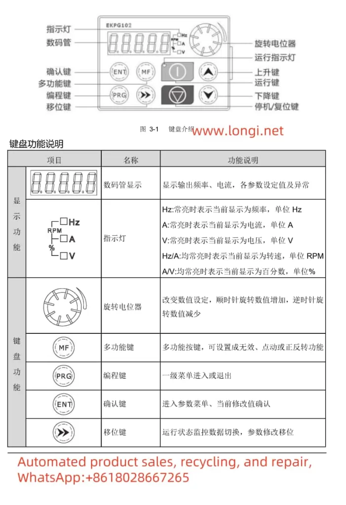
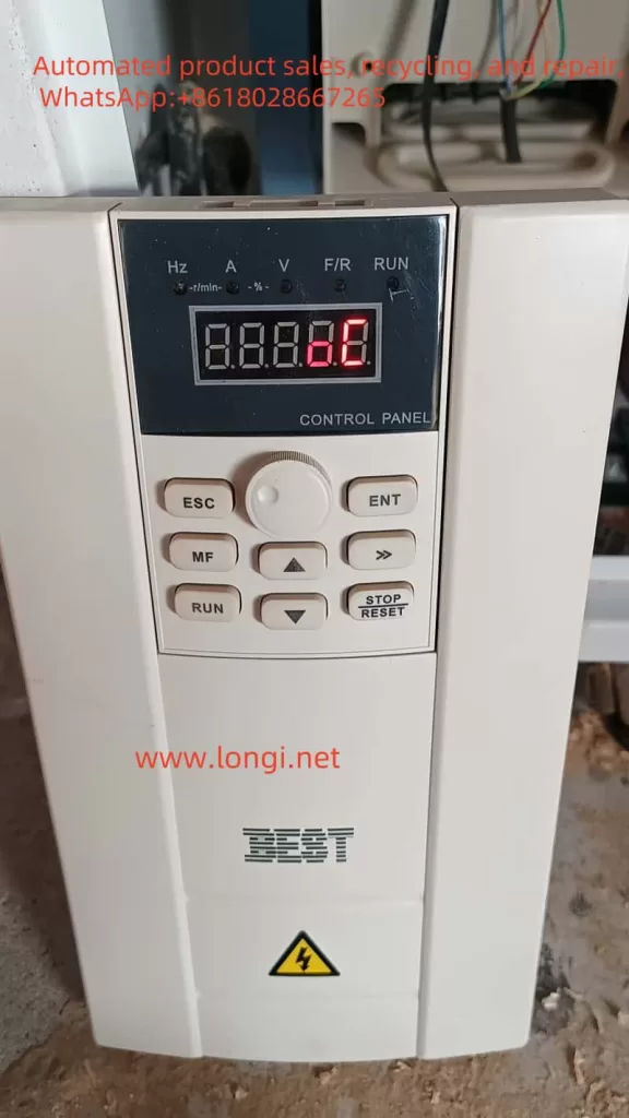
I. Introduction to the ATV303 Series Inverter Operation Panel

The Schneider ATV303 series inverter’s operation panel (also known as the display terminal or HMI) features an intuitive interface, allowing users to easily set parameters, monitor operational status, and troubleshoot errors. The primary functions of the operation panel include:

  • Display Screen: Displays the current status, parameter values, error messages, etc., of the inverter.
  • Navigation Buttons: Used to navigate between menus and parameters, and to adjust parameter values.
  • Mode Button: Switches between “Given” (rEF), “Monitor” (MOn), and “Configuration” (ConF) modes.
  • Stop/Reset Button: Stops motor operation or resets faults under certain conditions.
  • Run Button: Starts motor operation.
ATV303 INVERTER  F014 FAULT

Setting and Removing Passwords

To prevent unauthorized access, users can set a password for the inverter. Here’s how:

  1. Enter “Configuration” mode (ConF).
  2. Select the “Maintenance” menu (900-).
  3. Locate the “HMI Password” parameter (999).
  4. Enter the desired password value (range: 2-9999) and press the “Confirm” button to save.

To remove the password, simply set the “HMI Password” parameter (999) to “OFF”.

Restoring Factory Settings

To reset the inverter’s parameters to their factory defaults, follow these steps:

  1. Enter “Configuration” mode (ConF).
  2. Select the “Store/Restore Parameter Sets” menu.
  3. Set the “Factory/Restore Customer Parameter Settings” parameter (102) to “64”. The inverter will restart automatically and apply the factory settings.
Schneider inverter ATV303 control terminal wiring diagram

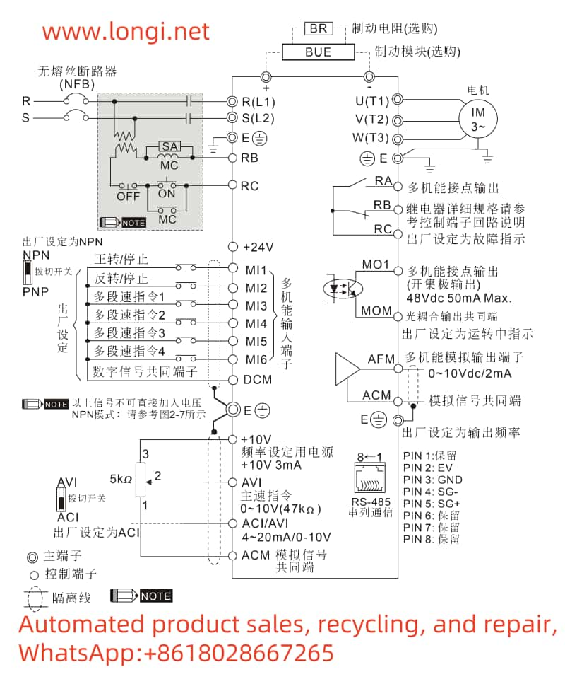
II. Terminal Forward/Reverse Control and External Potentiometer Speed Regulation

Terminal Forward/Reverse Control

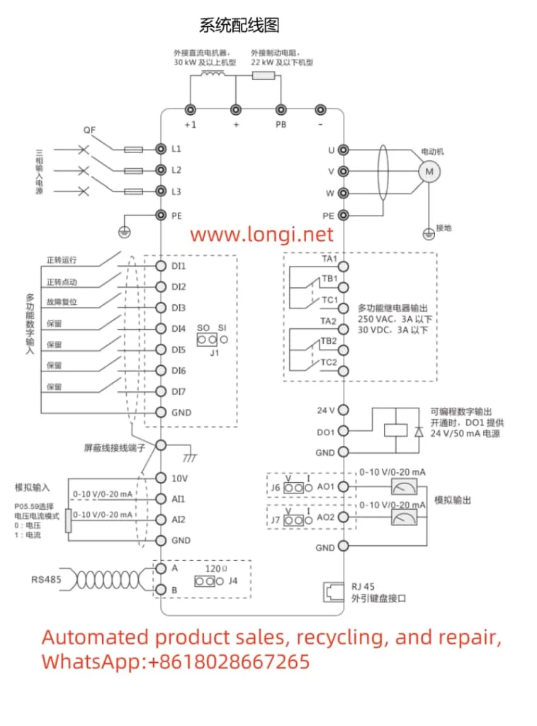
To achieve motor forward/reverse control via the inverter’s control terminals, follow these setup and wiring steps:

  1. Parameter Settings:
    • Enter “Configuration” mode (ConF).
    • Select the “Input/Output” menu (200-).
    • Set the “Control Type” parameter (201) to “2-wire control” or “3-wire control”.
    • For “2-wire control”, configure the “2-wire Control” parameter (202), e.g., “Forward Priority”.
    • Set the “Reverse” parameter (503) to specify which logic input terminal controls reversal (e.g., LI2H for LI2 high level reversal).
  2. Wiring:
    • Connect the motor forward control terminal (e.g., LI1) to the forward control signal source.
    • Connect the motor reverse control terminal (e.g., LI2, based on parameter settings) to the reverse control signal source.
    • Ensure all control signal sources are passive dry contacts or provide appropriate level signals.

External Potentiometer Speed Regulation

To regulate inverter speed using an external potentiometer, configure the following parameters and connect the corresponding terminals:

  1. Parameter Settings:
    • Enter “Configuration” mode (ConF).
    • Select the “Control” menu (400-).
    • Set the “Given Channel 1” parameter (401) to “183” to receive speed input via analog input AI1.
    • Set the “AI1 Type” parameter (204.0) to “Voltage” or “Current” based on the external potentiometer’s output type.
    • For current output, also set the “0% AI1 Current Ratio Parameter” (204.1) and “AI1 Current Calibration Parameter 100%” (204.2).
  2. Wiring:
    • Connect the external potentiometer’s output terminal to the inverter’s analog input terminal AI1.
    • Connect the external potentiometer’s power terminals (if needed) to the inverter’s +5V and COM terminals, or provide an external power supply.

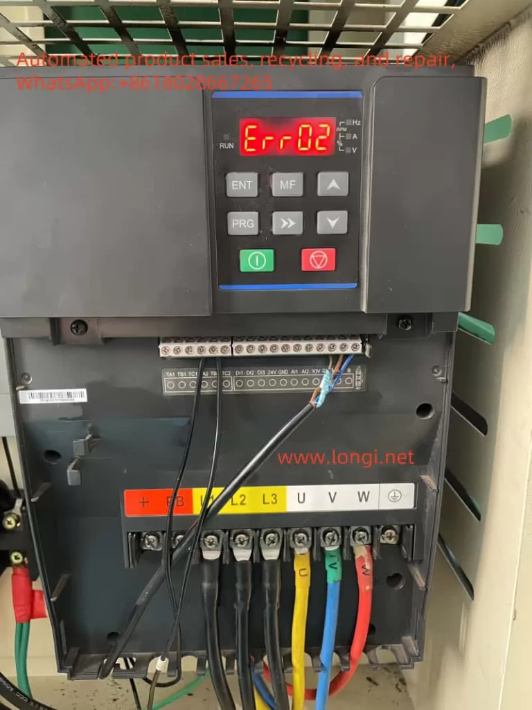
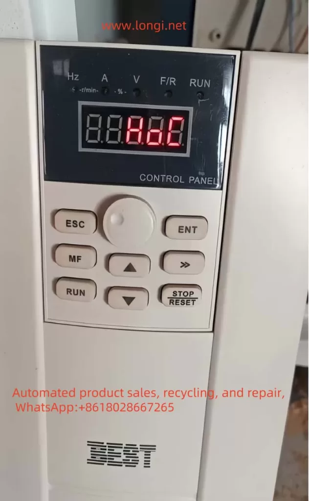
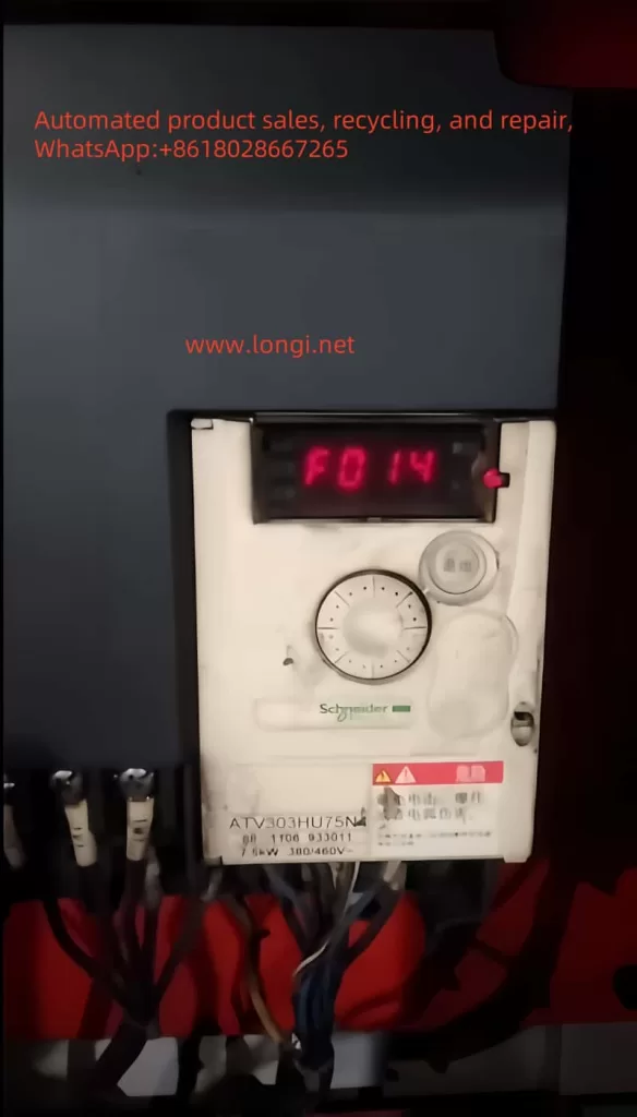
III. F014 Fault Resolution Method

F014 Fault Overview

The F014 fault indicates that one phase is missing from the inverter’s output to the motor. This fault can cause abnormal motor operation or even damage to the motor and inverter.

Mechanism of Occurrence

The primary mechanisms behind the output phase loss fault include:

  1. Loose or Poor Output Terminal Connections: Loose or poor contact between the inverter output terminals and motor connection terminals may prevent the transmission of electrical energy in one phase.
  2. Motor or Cable Faults: Internal motor winding damage or cable breaks can also lead to output phase loss.
  3. Inverter Internal Faults: Damage to power devices or control circuit faults within the inverter can cause output phase loss.

Repair Method

To resolve the F014 fault, follow these troubleshooting steps:

  1. Check Output Terminal Connections: Verify that the connections between the inverter output terminals and motor connection terminals are secure and free from loose or poor contacts.
  2. Inspect the Motor and Cable: Use a multimeter or other tool to check the continuity of the motor windings and cables, ensuring there are no breaks or shorts.
  3. Examine the Inverter Internals: If the above checks are clear, the fault may lie within the inverter. Disassemble and inspect the inverter for damaged power devices or control circuit faults, and perform necessary repairs or replacements.
  4. Re-execute Autotuning: After ruling out hardware faults, re-execute the inverter’s autotuning process to ensure correct parameter settings and normal motor operation.

By following these steps, users can effectively resolve the F014 fault on the ATV303 series inverter and restore normal device operation. Regular inspections and maintenance of the inverter are recommended to prevent similar faults from occurring.

Posted on

Huayuan Inverter User Manual Usage Guide and ERR02 Fault Solution

I. Introduction to the Function of Huayuan Inverter G1 Series Operating Panel (Keyboard)

Function diagram of Huayuan inverter keyboard

Operating Panel Functionality

The Huayuan Inverter G1 Series operating panel integrates multiple functions to facilitate parameter setting, status monitoring, and fault diagnosis. The panel primarily consists of a 5-digit 8-segment LED display, 4 indicator lights, 8 buttons, and a rotary potentiometer.

  • LED Display: Shows output frequency, current, various parameter settings, and abnormal statuses.
  • Indicator Lights: Indicate the current operating mode (e.g., Hz, A, V).
  • Button Functions:
    • Rotary Potentiometer: Used to adjust numerical settings; clockwise rotation increases the value, while counterclockwise rotation decreases it.
    • Multifunction Button: Can be set to invalid, jog, or forward/reverse functions.
    • Program Button: Enters or exits the parameter menu.
    • Confirm Button: Enters the parameter menu and confirms current modifications.
    • Shift Button: Switches between running status monitoring data and shifts parameters during modification.
    • Run Button: Controls the start and stop of the inverter.
    • Stop/Reset Button: Stops the inverter or resets faults.
    • Up/Down Buttons: Increases or decreases function codes or values.
Huayuan Inverter G1 Series Wiring Diagram

Parameter Upload and Download

  • Parameter Upload: Copies the internal parameters of the inverter to the keyboard memory. Set function parameter P07.02=H.#1, press the “‖” button to start the upload, and “CoPy” will be displayed upon completion.
  • Parameter Download: Writes the parameters stored in the keyboard to the inverter. Set function parameter P07.02 to H.12 or H.13, press the “‖” button to start the download, and “LoAd” will be displayed upon completion.

Setting Open-Loop Vector Control (SVC) and Closed-Loop Vector Control (FVC) Modes

  • Open-Loop Vector Control (SVC):
    1. Set P00.00=1.
    2. Set motor parameters (P02.01~P02.05) according to the motor nameplate.
    3. Perform motor parameter tuning (P00.25=1 for static tuning, P00.25=2 for dynamic tuning).
  • Closed-Loop Vector Control (FVC):
    1. Set P00.00=2.
    2. Set motor parameters (P02.01~P02.05) according to the motor nameplate.
    3. Set encoder-related parameters (e.g., P20.00 sets the encoder line count, P20.02 enables the PG card encoder function).
    4. Perform motor parameter tuning (P00.25=1 for static tuning, P00.25=2 for dynamic tuning).

Initializing Parameters

  • By setting function parameter P00.26, you can choose to restore factory default parameters (excluding or including motor parameters).

II. External Terminal Control

Achieving Forward/Reverse Rotation and Potentiometer Speed Adjustment

Terminal Connections

  • Forward/Reverse Control:
    • For forward rotation, connect the DI1 terminal to the common terminal (COM).
    • For reverse rotation, connect the DI2 terminal to the common terminal (COM).
  • Potentiometer Speed Adjustment:
    • Connect the output end of the external potentiometer to AI1 or AI2, and the other end to the common terminal (COM).

Parameter Settings

  • Forward/Reverse Parameters:
    • Set P05.00 (DI1 function) = 1 (forward rotation) or 2 (reverse rotation).
    • Ensure P00.01 (command source selection) = 0 (keyboard control) or change it to 1 (terminal control) as needed.
  • Potentiometer Speed Adjustment Parameters:
    • Set P00.02 (main frequency source X selection) = 1 (AI1) or select other analog inputs as needed.
    • Ensure P05.59 (AI voltage or current selection) is set correctly (e.g., 00 indicates AI1 is a voltage input).
err02 fault

III. ERR02 Fault Solution

Meaning of ERR02 Fault

ERR02 indicates an “acceleration overcurrent fault,” meaning an overcurrent is detected during inverter acceleration.

Fault Causes and Solutions

  1. Grounding or Short Circuit in Inverter Output Circuit:
    • Check and eliminate grounding or short circuits in peripheral wiring.
  2. Vector Control Mode Without Parameter Tuning:
    • Ensure motor parameter tuning has been correctly performed (SVC or FVC mode).
  3. Too Short Acceleration Time:
    • Increase the acceleration time (P00.17 or P00.18).
  4. Inappropriate Manual Torque Boost or V/F Curve:
    • Adjust the manual torque boost (P04.01) or select an appropriate V/F curve (P04.00).
  5. Low Voltage:
    • Adjust the voltage to the normal range.
  6. Starting a Rotating Motor:
    • Choose speed tracking start or wait for the motor to stop before starting.
  7. Sudden Load Increase During Acceleration:
    • Eliminate sudden load increases or reassess the load condition.
  8. Undersized Inverter Selection:
    • Select an inverter with a higher power rating.

Repairing the Inverter

If the above methods cannot resolve the ERR02 fault, further inspection and repair of the inverter may be necessary:

  1. Check the Drive Board and Main Control Board:
    • Confirm that the drive board and main control board are functioning normally, and replace faulty components if necessary.
  2. Check the Hall Sensor:
    • Confirm that the Hall sensor is operating correctly, and replace it if damaged.
  3. Contact the Manufacturer or Professional Repair Service:
    • If the problem persists, it is recommended to contact the inverter manufacturer or a professional repair service for further inspection and repair.

Conclusion

The Huayuan Inverter G1 Series user manual provides a detailed operation guide and fault solution. By correctly setting parameters and using external terminal control, various functions of the inverter can be realized. For the ERR02 fault, the inverter can be restored to normal operation by troubleshooting and solving the problem step by step. When necessary, contacting the manufacturer or a professional repair service is crucial to ensuring reliable operation of the equipment.

Posted on

Analysis and Solutions for the 3130 Fault in ABB Inverter ACH531

Introduction

The ABB inverter ACH531 is a high-performance drive equipment widely used in HVAC (Heating, Ventilation, and Air Conditioning) systems. However, during operation, various fault alerts may be encountered, with the 3130 fault being a relatively common one. This article will provide a detailed analysis of the meaning of the 3130 fault in the ABB inverter ACH531 and propose corresponding solutions to help technicians quickly locate and resolve the issue, ensuring stable operation of the equipment.

ACH531 Inverter

I. Meaning of the 3130 Fault

The 3130 fault in the ABB inverter ACH531 is defined as an input phase loss fault, also known as a DC voltage oscillation fault. The appearance of this fault code indicates that the inverter has detected an issue with the input power supply, resulting in fluctuations in the DC bus voltage exceeding the normal range (exceeding 13%). This fault typically causes the inverter to shut down to protect the motor and drive system from damage.

II. Cause Analysis of the 3130 Fault

  1. Power Phase Loss or Fuse Blowing:
    • When one phase of the input power supply to the inverter is missing or a fuse blows, it can lead to instability in the DC circuit voltage, triggering the 3130 fault.
  2. Excessive DC Filter Capacitor Discharge and Insufficient Power Supply:
    • The DC filter capacitors inside the inverter are used to smooth the DC bus voltage. If the capacitors discharge excessively and the power supply is insufficient, it can cause increased fluctuations in the DC bus voltage, leading to the 3130 fault.
  3. Power Grid Interference:
    • Interference factors such as imbalances, harmonics, or transient overvoltages in the power grid can affect the normal operation of the inverter and trigger the 3130 fault.
  4. Oscillation Issues Under Heavy Loads:
    • Under heavy load conditions, if the inverter’s parameter settings are unreasonable or the load fluctuates significantly, it may also cause DC bus voltage oscillation, leading to the 3130 fault.
  5. Hardware Failures:
    • Hardware failures such as the rectifier bridge, thyristors, and their trigger circuits inside the inverter may also cause the 3130 fault.
fault 3130

III. Solutions for the 3130 Fault

  1. Check Power Supply and Fuse:
    • First, check whether the input power supply to the inverter is stable and whether the three-phase voltage is balanced. Use a multimeter to measure the incoming voltage and ensure that the voltage of each phase is within the normal range.
    • Check whether the fuse has blown and, if so, replace it with a new one promptly.
  2. Check Rectifier Bridge and Thyristors:
    • Examine the thyristors and their trigger circuits inside the rectifier bridge for anomalies. An oscilloscope can be used to observe the trigger waveform of the thyristors to ensure their normal operation.
    • If a thyristor or trigger circuit fault is found, it should be replaced or repaired in a timely manner.
  3. Test DC Bus Voltage:
    • Test the actual value of the DC bus voltage under load to see if it fluctuates. If the actual value does not fluctuate while the detected value does, it may indicate a fault in the detection circuit.
    • In such cases, consider replacing the relevant detection components, such as sensors or circuit boards.
  4. Check Capacitor Capacity:
    • Check whether the capacity of the DC filter capacitors has decreased. If the capacitor capacity is insufficient, replace it with a new one to improve the stability of the DC bus voltage.
  5. Check Power Input Terminal:
    • Examine whether the wiring at the power input terminal is secure, with no loosening or poor contact.
    • Check whether the capacity of the power supply transformer meets the load requirements of the inverter system. If the transformer capacity is insufficient, replace it with a larger one.
    • Check whether the switches or circuit breakers are qualified, whether the fuse has blown, and whether the thermal relay has tripped.
  6. Adjust Parameter Settings:
    • Under heavy load conditions, try adjusting the inverter’s parameter settings, such as increasing acceleration and deceleration times or optimizing load balancing designs, to improve the stability of the DC bus voltage.
    • If needed, the 3130 fault can be masked by setting parameter 31.21 (input phase loss) to “0”, so that the inverter will not trip when it detects input phase loss. However, please note that this method is only a temporary measure, and the root problem still needs to be solved in the long run.
  7. Check Other Hardware Faults:
    • If the above methods fail to resolve the issue, further examine other hardware components inside the inverter, such as the RTAC (Real-Time Adaptive Control) module and the AIBP (Input Bridge Protection Board), for damage or poor insertion.
    • If hardware faults are found, replace or repair the corresponding components promptly.

IV. Conclusion

When the ABB inverter ACH531 encounters the 3130 fault, it should be troubleshooted and resolved from multiple aspects, including the power supply and fuse, rectifier bridge and thyristors, DC bus voltage testing, capacitor capacity, power input terminal, parameter settings, and other hardware faults. Through systematic inspection and adjustment, the 3130 fault can be effectively located and resolved, ensuring stable operation of the inverter. Meanwhile, it is also recommended to regularly maintain and service the inverter to prevent faults from occurring.

Posted on

VACON NX Inverter Series User Manual Guide

I. How to Achieve Forward/Reverse Rotation and Speed Control via External Terminals

The VACON NX series of frequency converters allows for straightforward forward/reverse rotation and speed control via external terminals. Here’s how to achieve this:

Application diagram of VACON inverter NX series control IO
  1. Terminal Connections:
    • Forward/Reverse Control:
      • Forward rotation is typically connected to the DI1 (forward start) terminal of the frequency converter.
      • Reverse rotation is typically connected to the DI2 (reverse start) terminal.
      • Note that different NX series models may have different terminal numbers; refer to the specific model’s user manual for confirmation.
    • Potentiometer Speed Control:
      • Connect the three terminals of the potentiometer to the AI1 (analog input 1), GND (ground), and +10V (analog input positive power) terminals of the frequency converter, respectively.
  2. Parameter Settings:
    • Forward/Reverse Parameters:
      • Set the control source to external terminal control and ensure that the DI1 and DI2 functions are correctly configured for forward and reverse rotation.
    • Potentiometer Speed Control Parameters:
      • Set AI1 as the frequency reference source.
      • Adjust the input range of AI1 as needed to ensure that the potentiometer’s output range matches the frequency converter’s frequency range.
VACON inverter NX series PID control IO wiring diagram

II. Characteristics of PID Function and Its Application in Constant Pressure Control of Water Pumps

The PID function of the VACON NX series frequency converter is highly capable and suitable for various automatic control applications. Here are its key features and how to apply it to constant pressure control of water pumps:

  1. PID Function Characteristics:
    • Supports multiple PID control modes, including standard PID and sleep/wake-up functions.
    • Flexible PID parameter configuration via external terminals or fieldbus.
    • Provides comprehensive monitoring and alarm functions to ensure stable system operation.
  2. Application in Water Pump Constant Pressure Control:
    • Terminal Connections:
      • Connect the output signal of the pressure sensor to the AI1 (analog input 1) terminal of the frequency converter.
      • Connect other control terminals as needed, such as start and stop.
    • Parameter Settings:
      • Set AI1 as the actual value input for PID control.
      • Configure the reference value for the PID controller (target pressure value).
      • Adjust the PID parameters (proportional, integral, derivative) to achieve optimal control performance.
      • Set the sleep/wake-up function as needed to save energy.

III. Fieldbus Protocol and Communication with Siemens PLC

The VACON NX series supports multiple fieldbus protocols, including Profibus, Modbus, etc., facilitating communication with various PLCs. Here’s how to set up communication with a Siemens PLC:

  1. Fieldbus Protocol:
    • The NX series supports multiple fieldbus protocols; users can select the appropriate protocol based on actual needs.
  2. Communication with Siemens PLC:
    • Wiring:
      • Connect the frequency converter’s fieldbus interface to the corresponding interface of the Siemens PLC using a dedicated fieldbus communication cable.
    • Parameter Settings:
      • Configure fieldbus parameters in the frequency converter, including station address, baud rate, etc.
      • Configure corresponding communication parameters in the Siemens PLC to ensure compatibility with the frequency converter.
      • Program the PLC to send start, stop, and speed adjustment commands to the frequency converter via the fieldbus.

IV. Fault Code Meaning Analysis and Troubleshooting

The VACON NX series provides comprehensive fault codes to help users quickly locate and resolve issues. Here are some common fault codes, their meanings, and troubleshooting methods:

  1. F1: Overcurrent Fault
    • Meaning: The output current of the frequency converter exceeds the set value.
    • Troubleshooting: Check for motor overload, cable short circuits, and correct frequency converter parameter settings.
  2. F2: Overvoltage Fault
    • Meaning: The DC bus voltage of the frequency converter is too high.
    • Troubleshooting: Check for stable input voltage and proper operation of the braking resistor.
  3. F5: Charging Switch Fault
    • Meaning: The internal charging switch of the frequency converter is abnormal.
    • Troubleshooting: Check the charging switch and related circuits for proper functioning.

V. Conclusion

The VACON NX series user manual provides detailed usage guides and parameter setting instructions, helping users quickly get started and implement various complex control functions. Through this guide, users should now have a comprehensive understanding of how to achieve forward/reverse rotation and speed control via external terminals, the characteristics and application of the PID function, fieldbus protocol and communication with Siemens PLC, as well as the meanings and troubleshooting methods of fault codes. In practical applications, users should flexibly configure parameters and wiring based on specific needs and site conditions to achieve optimal control performance.

Posted on

Delta VFD-E Series Inverter User Manual Operation Guide

I. Introduction to the Panel Functions and Operations of the Delta VFD-E Series Inverter

VFD-E inverter

Panel Function Introduction

The panel of the Delta VFD-E series inverter primarily consists of the following function keys and display areas:

  • Power Indicator: Indicates whether the inverter is powered on.
  • RUN Indicator: Indicates the running status of the inverter.
  • FREQ Display: Displays the current operating frequency of the inverter.
  • MODE Key: Switches between different modes for parameter setting and monitoring.
  • ▲/▼ Keys: Used for increasing or decreasing parameter values or frequency settings.
  • STOP Key: Stops the operation of the inverter.
  • RESET Key: Resets the inverter to its initial state or clears fault alarms.
  • ENTER Key: Confirms the setting of parameters.
  • JOG Key: Enables jogging (inching) operation of the motor.
  • FWD/REV Keys: Controls the forward and reverse rotation of the motor.

Panel Operations

Copying Parameters to Another Inverter

  1. Connect to the Inverter: Use a suitable communication cable to connect the source inverter (containing the desired parameters) to the target inverter.
  2. Enter Copy Mode: On the source inverter, press the MODE key until the “Copy” mode is displayed.
  3. Initiate Copy: Press the ENTER key to initiate the parameter copy process.
  4. Complete Copy: Follow the prompts on the display to complete the parameter copy. Disconnect the communication cable after copying is finished.

Setting and Removing Passwords

Setting a Password:

  1. Navigate to the parameter group 00 User Parameters.
  2. Select parameter 00-08 Parameter Protection Password.
  3. Enter the desired password value (00-65535).
  4. Press ENTER to confirm.

Removing a Password:

  1. Navigate to the parameter group 00 User Parameters.
  2. Select parameter 00-08 Parameter Protection Password.
  3. Enter the password value you want to remove (set it to 00).
  4. Press ENTER to confirm.

Resetting to Factory Defaults

  1. Navigate to the parameter group 00 User Parameters.
  2. Select parameter 00-02 Parameter Reset Setting.
  3. Set the value to 09 for resetting to factory defaults at 50Hz, or 10 for resetting to factory defaults at 60Hz.
  4. Press ENTER to confirm and restart the inverter to apply the reset.
Delta VFD-E inverter standard wiring diagram

II. Terminal Control for Forward/Reverse Start and Stop

Terminal Control Configuration

  1. External Terminal Connection: Connect the external control terminals (FWD, REV, STOP) to the corresponding terminals on the inverter.
  2. Parameter Configuration:
    • Navigate to the parameter group 02 Operation Mode Parameters.
    • Set parameter 02-01 First Operation Command Source to 01 (External Terminal).
    • Set parameter 02-05 Two-Wire/Three-Wire Control to the desired control mode (e.g., 00 for two-wire control).
  3. Control Logic:
    • Forward Rotation: Close the FWD terminal and open the REV terminal.
    • Reverse Rotation: Close the REV terminal and open the FWD terminal.
    • Stop: Open both the FWD and REV terminals.

Monitoring and Troubleshooting

  • Monitoring: Use the inverter panel or an external monitoring device to check the operating status and parameters.
  • Troubleshooting: Refer to the inverter’s fault codes and troubleshooting guide in the user manual to diagnose and resolve issues.

By following the above steps, users can effectively operate and configure the Delta VFD-E series inverter for various applications, including terminal control for forward/reverse start and stop, parameter copying, password setting/removal, and resetting to factory defaults.

Posted on

BEST Inverter FC300 User Manual Usage Guide and Distinction between HOC and OC Faults

I. Introduction to BEST Inverter FC300 Panel Functions and Parameter Settings

1.1 Introduction to Panel Functions

The BEST Inverter FC300’s operation panel is equipped with multiple function keys, including ESC, ENT, MF, >>, ↑, ↓, STOP/RESET, each with specific functions:

  • ESC: Exits the current setting or cancels the current operation.
  • ENT: Confirms the current setting or proceeds to the next operation.
  • MF: Multifunction key with different functions depending on the context.
  • >>: Switches between menus or parameters.
  •  and : Adjust parameter values or scroll through menus.
  • STOP/RESET: Stops the inverter operation or resets the fault status.
OC FAULT

1.2 Parameter Initialization and Upload/Download

The BEST Inverter FC300 supports parameter initialization, upload, and download, primarily through parameter P087.

  • Parameter Initialization: Set P087 to 1 and press ENT to confirm, restoring the inverter to factory settings.
  • Parameter Upload: Set P087 to 4, ensure correct connection between the inverter and computer, and upload current parameter settings via dedicated software.
  • Parameter Download: Set P087 to 5, ensure correct connection, and download parameters to the inverter via software.

1.3 Setting and Removing Passwords

To protect the inverter settings from unauthorized changes, the BAST FC300 supports password protection.

  • Setting a Password: Set a new password in P086 and choose 2 in P087 to memorize the password.
  • Removing a Password: Enter the current password in P086 and choose 3 in P087 to clear the password.

II. Terminal Start/Stop, Potentiometer Speed Adjustment, and Forward/Reverse Control

2.1 Terminal Start/Stop and Potentiometer Speed Adjustment

To achieve terminal-based start/stop of the inverter and potentiometer-based speed adjustment, correct wiring and parameter settings are required.

  • Wiring: Connect the start and stop signals to the X1 and X3 terminals of the inverter, respectively (or other designated terminals, as per the manual). Connect the potentiometer to the AVI or ACI terminals for analog speed adjustment.
  • Parameter Settings:
    • Set P064 to 1 to select external terminal control.
    • Configure the function of the AVI or ACI terminals, e.g., set P091’s X1 function to “Forward Start” and X3 to “Stop”.
    • Adjust parameters like P053 as needed to set the range and mode of analog speed adjustment.
HOC FAULT

2.2 Terminal-Based Forward/Reverse Control

To achieve terminal-based forward/reverse control of the inverter, correct wiring and parameter settings are also necessary.

  • Wiring: Connect the forward and reverse signals to the X1 and X2 terminals of the inverter, respectively (or other designated terminals).
  • Parameter Settings:
    • Ensure P064 is set to support external terminal control.
    • Configure the functions of the X1 and X2 terminals, e.g., set P091’s X1 function to “Forward” and X2 to “Reverse”.
    • Adjust parameters like P066 as needed to ensure motor reversal is allowed.

III. Distinction between HOC and OC Faults and Solutions

3.1 Distinction between HOC and OC Faults

  • HOC Fault: Typically refers to an overcurrent fault caused by damage to the inverter’s inverter module. This fault is severe and may be accompanied by damage to internal components of the inverter.
  • OC Fault: Generally refers to an overcurrent fault on the output side, which may be caused by motor stalls, excessive loads, short acceleration times, etc.

3.2 Fault Solutions

  • HOC Fault Solution:
    1. Check the Inverter Module: Confirm if the inverter module is damaged and replace it if necessary.
    2. Check the Drive Circuit: Inspect the drive circuit for normal function and troubleshoot drive faults.
    3. Contact the Manufacturer: If the issue is complex or unresolved, contact BAST for repair or replacement.
  • OC Fault Solution:
    1. Check the Motor and Load: Confirm if the motor is stalled or if the load is excessive, and adjust the load or motor parameters as necessary.
    2. Adjust Acceleration Time: Increase the acceleration time to avoid instantaneous overcurrent during motor startup.
    3. Check Wiring: Verify the wiring between the motor and the inverter for correctness and eliminate any wiring errors that may cause faults.
    4. Reset the Inverter: Press the STOP/RESET button to reset the inverter and attempt to restart it.

IV. Conclusion

The BEST Inverter FC300, as a high-performance inverter, boasts a rich set of panel functions and flexible parameter settings, capable of meeting control demands in various complex operating conditions. Through correct wiring and parameter settings, functions such as terminal-based start/stop, potentiometer speed adjustment, and forward/reverse control can be achieved. Meanwhile, for common HOC and OC faults, users should be able to quickly identify the fault phenomenon and take corresponding measures for resolution to ensure the normal operation of the inverter. During use, users must strictly adhere to the safety precautions and operating procedures outlined in the manual to ensure the safety of personnel and equipment.

Posted on

Guide to the LCGK-ZTV Inverter LC630 Series from Lianchuang High-Tech & Zhongtaiwei and Troubleshooting for Err23

I. Introduction to Panel Functions and Initialization Settings of the LCGK-ZTV Inverter LC630 Series

1. Panel Function Introduction

The LC630 series inverters from LCGK-ZTV are equipped with an intuitive operation panel, which mainly includes a display screen, function keys, and status indicator lights. The display screen shows current working status, parameter settings, and other information; the function keys include “MENU” (menu), “ENTER” (confirm), “UP/DOWN” (selection), etc., used for parameter setting and navigation; the status indicator lights indicate power, operation, faults, and other statuses.

LC630 inverter

2. Initialization and Password Setting

Initializing the inverter typically involves restoring default parameter settings. The specific steps are as follows:

  • Press the “MENU” key to enter the main menu.
  • Use the “UP/DOWN” keys to select the “Initialization” option and press “ENTER” to confirm.
  • The system will prompt whether to confirm initialization; press “ENTER” again to execute.

The LCGK-ZTV Inverter LC630 series supports password protection to prevent unauthorized modifications. The method for setting a password is as follows:

  • After entering the main menu, select the “Parameter Protection” option.
  • Use the “UP/DOWN” keys to select “Password Setting,” and press “ENTER” to enter.
  • Input the desired password (typically a 4-digit number) and press “ENTER” to confirm.
  • Input the password again for confirmation and press “ENTER” to save.

The method for clearing the password is similar. Simply select “Clear Password” after entering the current password in the “Password Setting” option and press “ENTER” to confirm.

3. Setting Panel Start and Panel Potentiometer Speed Adjustment

To achieve panel start and panel potentiometer speed adjustment, the following parameters need to be set:

  • Pr033: Start source selection. Set to 0 for panel start; set to other values for external signal start.
  • Pr034: Operating frequency source selection. Set to 0 for panel potentiometer speed adjustment; set to other values for external signal speed adjustment.
  • Pr052: Enable PID function (set according to specific situations when used for constant pressure water supply control).

II. Method for Achieving Constant Pressure Water Supply Control

1. Introduction to PID Function

The PID control is key to achieving constant pressure water supply control with the inverter. By monitoring changes in water supply pressure, the PID controller automatically adjusts the output frequency of the inverter to maintain a constant water supply pressure.

2. Parameter Setting

According to the instruction manual for the LCGK-ZTV Inverter LC630 series (especially pages 58, 59, and 60), the following parameters need to be set to achieve constant pressure water supply control:

  • Pr052: Enable PID function. Set to a non-zero value to enable PID control.
  • Pr100: PID target value setting. Set the target value according to the required water supply pressure.
  • Pr101: PID feedback signal source selection. Typically, select the output signal from the pressure sensor as the feedback signal.
  • Pr102Pr103Pr104: Set the P (proportional), I (integral), and D (derivative) parameters of PID control, respectively. These parameters need to be adjusted according to the actual system response to achieve the best control effect.
  • Pr105: PID output limiting. Set the maximum and minimum values of the PID output signal to prevent the inverter output frequency from exceeding the allowed range.

3. Notes

  • When setting PID parameters, ensure system stability and quick response.
  • Regularly check the accuracy of the pressure sensor and feedback signal to ensure the accuracy of PID control.
  • Adjust PID parameters according to actual water supply demands and pump performance to achieve optimal energy-saving effects.
err23 fault

III. Troubleshooting for Err23

1. Fault Mechanism Analysis

The Err23 fault code typically indicates a short circuit between the inverter output and ground. This may be caused by insulation failure of the motor or motor cables. When a short circuit occurs between the inverter output and ground, an excessively large current is generated, triggering the protection mechanism and displaying the Err23 fault code.

2. Fault Handling Method

When handling the Err23 fault, first check the insulation of the cables and motor:

  • Disconnect the inverter’s power supply to ensure safe operation.
  • Use an insulation resistance tester to test the insulation of the cables and motor. Check the insulation resistance between each phase of the cable and ground, as well as the insulation resistance of the motor windings, to ensure they meet the requirements. If the insulation resistance value is too low, it indicates insulation failure.
  • For cables, replace them with new ones that match the specifications of the original cables. During replacement, ensure the integrity and insulation performance of the cables to avoid new damage during wiring.
  • For the motor, if the insulation failure is severe, the entire motor may need to be replaced. When replacing the motor, ensure that the specifications and performance of the new motor match those of the original motor to meet the operational requirements of the inverter.
  • If the Err23 fault code persists after replacing the cables or motor, it may be necessary to consider replacing the entire unit. This typically indicates that there may be other faults within the inverter causing the ground short circuit issue.
Posted on

Fault Analysis and Handling for Inverter Displaying “88888” upon Power-up, with All Indicators Lit and No Response to Any Button Press

In inverter maintenance, it is common to encounter a situation where upon power-up, the inverter displays “88888”, all indicators are lit, and pressing any button results in no response. This fault typically indicates the following possibilities:

INDVS inverter shows 88888
  1. Power Issues: For example, voltage fluctuations or instability may prevent the inverter from completing its initialization process.
  2. Hardware Faults: Components such as the control board, drive board, or power supply may be damaged or malfunctioning.
  3. Communication Problems: Interruptions or errors in communication between the inverter and other devices may cause abnormal displays.
  4. Software or Firmware Issues: There may be bugs or incompatibilities in the inverter’s software or firmware that need to be addressed.

To troubleshoot this issue, the following steps can be taken:

Inovance inverter shows 88888
  1. Check Power Supply: Ensure that the voltage is stable and within the operating range specified by the inverter.
  2. Inspect Hardware: Open the inverter’s casing and inspect the control board, drive board, and power supply for any signs of damage or malfunction. Replace any faulty components as necessary.
  3. Test Communication: Verify that the communication lines between the inverter and other devices are properly connected and free from interference.
  4. Update Software/Firmware: If suspected, try updating the inverter’s software or firmware to the latest version.
  5. Reset the Inverter: Perform a hard reset of the inverter to see if it can recover from a stuck initialization state.

If the above steps fail to resolve the issue, it is recommended to contact the manufacturer’s technical support or a professional repair service for further assistance. Regular maintenance and inspections can also help prevent such faults from occurring in the first place.

Posted on

Shenzhen SHZHD Inverter V680 Series Operation Guide and E10 Fault Handling

Shenzhen SHZHD Inverter V680 Series Operation Guide and E10 Fault Handling

I. Operation Panel Function Introduction, Parameter Factory Reset, and Password Management

SHZHD INVERTER V680

1. Operation Panel Function Introduction

The operation panel of the Shenzhen SHZHD Inverter V680 series provides an intuitive operation interface, allowing users to set various parameters and operate the inverter through buttons and displays on the panel. The main functions of the panel include:

  • Display Area: Displays current set frequency, output frequency, current, voltage, and other parameters.
  • Function Keys: Such as MENU, ENTER, △, ▽, used for entering menus, confirming settings, and adjusting parameters.
  • Run Key: Starts and stops the inverter.
  • Fault Indicator: When the inverter malfunctions, the corresponding indicator light will illuminate, prompting the user to check the fault.

2. Parameter Factory Reset

To restore the inverter’s parameters to their factory defaults, follow these steps:

  1. Enter the menu interface and find the “Parameter Initialization” option.
  2. Select “Restore Factory Parameters” and confirm execution. At this point, all parameters except motor parameters will be restored to their factory settings.

3. Adding and Removing Passwords

To protect parameters from being modified casually, users can set passwords for the inverter.

  • Adding a Password: Enter the “User Password” setting, input the desired password, and confirm to save.
  • Removing a Password: Re-enter the “User Password” setting and set the password to 0 to remove password protection.

II. Torque Control and Vector Control

1. Torque Control

Torque control is a special control mode that allows users to directly set the output torque of the inverter instead of indirectly controlling the torque by setting the frequency. This control mode is very useful in situations where precise control of the load torque is required.

  • Setting Method: First, select “Torque Control” in the control mode. Then, choose the torque setting source through the corresponding parameter (such as A0-01), which can be the keyboard, analog input, communication, etc. Finally, set the desired torque value through parameters such as A0-03.

2. Vector Control

Vector control is a high-performance control method that achieves high-precision speed and torque control by precisely controlling the motor’s current and magnetic flux.

  • Optimizing Parameters: To obtain better vector control performance, users need to adjust related parameters based on the actual load conditions, such as the speed loop proportional gain (P2-00, P2-03) and speed loop integral time (P2-01, P2-04). The adjustment of these parameters requires certain professional knowledge and experience.

III. Terminal Start/Stop and Potentiometer Speed Regulation

1. Terminal Start/Stop

Controlling the start and stop of the inverter through external terminals is a commonly used control method. Users need to set the control mode of the inverter to “Terminal Control” and wire it correctly.

  • Wiring Terminals: Typically include the forward start terminal (e.g., DI1), reverse start terminal (e.g., DI2), and stop terminal (e.g., DI3).
  • Parameter Settings: Select “Terminal Command Channel” in P0-02 and set the corresponding terminal functions.

2. Potentiometer Speed Regulation

Potentiometer speed regulation is a simple speed regulation method where users can change the set frequency of the inverter by rotating the potentiometer, thereby achieving speed regulation.

  • Wiring Terminals: Connect the output end of the potentiometer to the analog input terminal of the inverter (e.g., AI1).
  • Parameter Settings: Select “Analog AI1 Setting” as the frequency source in P0-03.
E10 FAULT

IV. E10 Fault Handling

1. On-site Handling

The E10 fault typically indicates an overload of the inverter. When an overload fault occurs, users should first check if the load is too heavy or if the motor is stalled. If the load is normal, try increasing the inverter’s acceleration and deceleration times to reduce the impact on the motor.

2. Maintenance Handling

If on-site handling fails to resolve the issue, it may be necessary to disassemble the inverter for maintenance. During the maintenance process, focus on the following aspects:

  • Motor and Load: Confirm whether the motor and load are normal and free from mechanical faults or obstructions.
  • Inverter Parameters: Check whether the inverter’s overload protection parameters (such as P9-00, P9-01) are set reasonably.
  • Hardware Faults: If the parameter settings are normal and the load is without abnormality, it may be a hardware fault within the inverter, such as damaged power devices or poor heat dissipation. At this point, professional maintenance personnel should be sought for assistance.

Conclusion

The Shenzhen SHZHD Inverter V680 series is a powerful and flexible inverter product. Through this guide, users can better understand the inverter’s operation panel functions, parameter setting methods, the application of torque control and vector control, and common fault handling methods. In practical applications, users should configure parameters and control modes based on specific needs and load conditions to ensure stable operation and high performance of the inverter.

Posted on

User Manual and Operating Guide for Hitachi Inverter SJ300


I. Basic Operation and Monitoring Functions

  1. Panel Setting and Monitoring
    Setting to Display Current, Bus Voltage, and Frequency

Display Current: First, enter the monitoring mode via the panel buttons (typically by selecting the monitoring mode with the “FUNC” key). In monitoring mode, use the up and down arrow keys to browse through different monitoring parameters, find the current monitoring item, and confirm.
Display Bus Voltage: Similarly, in monitoring mode, use the up and down arrow keys to find the bus voltage monitoring item and confirm.
Display Frequency: Frequency is one of the most commonly used monitoring parameters and is usually directly displayed on the main interface of the monitoring mode. If not displayed, select the frequency monitoring item with the arrow keys.
Monitoring Terminal Status

Enter monitoring mode, then select “Smart Input Terminal Status” or “Smart Output Terminal Status” for monitoring. These statuses include the switching state of the terminals, signal voltage, etc.
Panel Start/Stop and Speed Adjustment

Functional diagram of the operation panel for Hitachi inverter SJ300.

Start and Stop: In standard setting mode, start the inverter with the “RUN” key and stop it with the “STOP/RESET” key.
Speed Adjustment: Speed adjustment is typically achieved by changing the frequency setting value. On the panel, use the up and down arrow keys to adjust the frequency setting value, then press the “Store” key to confirm.
II. Multi-Speed Function Setting

  1. Setting Multi-Speed
    Assuming four speeds are needed, namely 10Hz, 20Hz, 40Hz, and 50Hz, the specific steps are as follows:

Wiring:
Connect external control signals (such as switch signals) to the inverter’s multi-speed control terminals (such as FW, 8, 7, 6, etc.).
Ensure correct connection of the control signal power supply and grounding.
Parameter Setting:
Enter standard setting mode and find parameters related to multi-speed control (such as A038, A039, etc.).
Set A038=00 (indicating external terminal control for multi-speed).
Set A039=04 (indicating 4-speed control).
Set the corresponding frequency values for the four speeds in the “F001” parameter: F001=10Hz (first speed), A020=20Hz (second speed), A220=40Hz (third speed), A320=50Hz (fourth speed).
III. Communication Protocol Setting

Standard wiring diagram for Hitachi inverter SJ300.
  1. Communication with Mitsubishi FX2N Series PLC
    Communication Method: Assuming RS485 communication is used.
    Parameter Setting:
    In the inverter, set C070=03 (select RS485 communication).
    Set C071 to the desired baud rate (e.g., C071=04 for 4800bps).
    Set C072=1 (8 data bits).
    Set C073=7 (no parity check).
    Set C074=0 (1 stop bit).
    On the PLC side, configure the corresponding RS485 communication parameters to match the inverter.
    IV. Simple Analysis and Handling of Fault Codes
  2. Common Fault Codes
    E02: Overcurrent Alarm. Possible causes include excessive motor load, motor stall, etc. Troubleshooting includes checking motor load, checking for motor stall, etc.
    E03: Overload Alarm. Possible causes include the motor operating overloaded for a long time. Troubleshooting includes reducing the load, increasing motor capacity, etc.
    E05: Overvoltage Alarm. Possible causes include excessively high input voltage. Troubleshooting includes checking if the input voltage is normal, adding input voltage protection, etc.
  3. Handling Steps
    Check the Alarm Code: When the inverter alarms, first check the alarm code displayed on the panel.
    Analyze Possible Causes: Based on the alarm code and site conditions, analyze possible fault causes.
    Take Measures: Based on the analysis results, take corresponding troubleshooting measures.
    Reset the Inverter: After troubleshooting, press the “STOP/RESET” key to reset the inverter and restart it.
    V. Summary

The Hitachi Inverter SJ300 series user manual provides detailed operating instructions and parameter setting methods. By carefully reading the manual and following the guidelines, users can easily monitor, control, and troubleshoot the inverter. Particular attention should be paid to correct parameter configuration and wiring accuracy when setting the multi-speed function and communicating with PLCs. Proper use of the inverter can significantly improve the operational efficiency and stability of the motor system.