Posted on

Methods for Unlocking Hidden Parameters and Modifying Mainboard Power of ABB ACS800 Series Inverters

The ABB ACS800 series inverters are high-performance inverters widely used in industrial control. To meet the needs of different application scenarios, users sometimes need to adjust the power of the inverter or unlock hidden parameters. The following will detail the methods for unlocking hidden parameters and modifying the mainboard power of the ACS800 series inverters.

Method for Unlocking Hidden Parameters

In the ACS800 series inverters, some parameters are hidden and can only be accessed by following specific steps. Here are the steps to unlock hidden parameters:

  1. Enter the parameter setting interface: First, enter the parameter setting interface of the inverter.
  2. Set the unlock code: Set parameter 16.03 (PASS CODE) to 358. This operation will unlock the hidden parameter groups and make them visible.
  3. Access hidden parameters: After unlocking, you can access hidden parameter groups such as group 112 and group 190.

By following these steps, users can access and modify parameters that are usually invisible for more advanced settings and adjustments.

Method for Modifying Mainboard Power

In some cases, users may need to adjust the power of the ACS800 inverter. The following are the steps for modifying the power of RDCU boards with different versions:

For RDCU Boards with Version Numbers Before 7200

  1. Enter parameter 9903 and change it to YES.
  2. Enter parameter 1603 and change it to 564.
  3. Enter parameter 11206 and select XXNONE.
  4. Power off and then on again.
  5. Re-enter parameter 1603 and change it to 564.
  6. Enter parameter 11206 and select the desired power (e.g., 170-3).
  7. Initialize the parameters.
  8. Power off and then on again.

For RDCU Boards with Version Numbers 7200 and Later

  1. Enter parameter 9903 and change it to YES.
  2. Enter parameter 1603 and change it to 564.
  3. Enter parameter 11221 and select the desired power (e.g., 170-3).
  4. Re-enter parameter 9903 and change it to YES.
  5. Power off and then on again.

Notes:

  • Parameters 11219 to 11223 correspond to different power levels. Be cautious when modifying them to select the correct parameters.
  • For inverters in normal use, do not operate or modify parameters arbitrarily to avoid losing normal parameters.
  • Using parameter 2303 can open single drive groups from 100 to 202.

Steps for Changing Inverter Type

In addition to changing the power, sometimes it is also necessary to change the type of inverter. Here are the steps for changing the inverter type:

  1. Set parameter 16.03 (PASS CODE) to 564 to make parameter groups 112 and 190 visible.
  2. Select the desired inverter type from parameter groups 112.20 to 112.36. For example, for an ACS800-01-0016-3 machine, select 11.21 = sr0016_3.
  3. The panel will prompt to power off. Power off the RMIO board and then on again.

Conclusion

By following these methods, users can unlock the hidden parameters of the ABB ACS800 series inverters and adjust the mainboard power and inverter type as needed. These operations can help users better adapt to different application scenarios and improve the flexibility and performance of the equipment. However, when performing these operations, be cautious and ensure that the correct parameters are selected to avoid affecting the normal operation of the equipment.

Posted on

CONVO Variable Frequency Drive G3/P3 Series User Manual Guide

The CONVO Variable Frequency Drive G3/P3 Series is a high-performance variable speed control device widely used in industrial automation, fans, pumps, and other fields. This article provides a detailed guide on the operation panel functions, parameter initialization, parameter copying, password setting and removal, parameter access restrictions, external terminal control, fault codes, and troubleshooting for the CONVO Variable Frequency Drive G3/P3 Series.

CVF-G3 physical working diagram

I. Introduction to Operation Panel Functions

The operation panel of the CONVO Variable Frequency Drive G3/P3 Series integrates multiple functions, including operation control, parameter settings, and status monitoring. The main function keys and their uses are as follows:

  1. RUN (Run): Starts the frequency drive.
  2. LOCAL/REMOT (Local/Remote): Switches between local control and remote control modes.
  3. FWD/REV (Forward/Reverse): Sets the running direction of the motor.
  4. TUNE/TC (Tune/Speed Adjustment): Enters the tuning or speed adjustment mode.
  5. PRG (Program): Enters the program setting mode.
  6. QUICK (Quick): Quickly sets the frequency.
  7. MF.K (Multifunction Key): Multifunction button used for operations in different modes.
  8. STOP/RST (Stop/Reset): Stops the frequency drive operation or resets the system.
  9. ENTER (Confirm): Confirms the current operation.
  10. ↑ (Up) and ↓ (Down): Adjusts parameter values or frequency.

Through these buttons, users can easily control the operation status of the frequency drive, set parameters, and monitor the system status.

II. Parameter Initialization (Restore Factory Settings)

Parameter initialization refers to restoring all parameters of the frequency drive to their factory settings. The specific operation steps are as follows:

  1. Enter the parameter setting mode: Press the PRG key to enter the parameter setting mode.
  2. Select parameter initialization: Use the or keys to select the parameter H-73 (Parameter Initialization).
  3. Set the initialization value: Set the value of H-73 to 1 (Restore factory settings by machine type) or 2 (Clear fault records).
  4. Confirm the operation: Press the ENTER key to confirm, and the frequency drive will automatically restore to the factory settings.

III. Using the Operation Panel to Copy Parameters to Another Frequency Drive of the Same Model

The parameter copying function allows users to copy the parameter settings from one frequency drive to another frequency drive of the same model. The specific operation steps are as follows:

  1. Prepare two frequency drives of the same model and ensure they are in the same initial state.
  2. On the source frequency drive, enter the parameter setting mode, select the parameter H-73, and set it to 3 (Parameter Copy).
  3. Use a communication cable to connect the RS485 interfaces of the two frequency drives.
  4. On the target frequency drive, enter the parameter setting mode, select the parameter H-73, and set it to 4 (Receive Parameters).
  5. Press the ENTER key, and the source frequency drive will transmit all parameters to the target frequency drive.
  6. After completion, disconnect the communication cable, and the parameter settings of the two frequency drives will be consistent.
G3-P3 series standard wiring diagram

IV. Setting and Removing Passwords

The CONVO Variable Frequency Drive G3/P3 Series supports setting passwords to protect parameter settings. The specific operation steps are as follows:

Setting a Password

  1. Enter the parameter setting mode: Press the PRG key to enter the parameter setting mode.
  2. Select password setting: Use the or keys to select the parameter H-79 (Password Setting).
  3. Enter the password: Press the ENTER key, enter a 4-digit numeric password, and then press the ENTER key to confirm.

Removing a Password

  1. Enter the parameter setting mode: Press the PRG key to enter the parameter setting mode.
  2. Select password setting: Use the or keys to select the parameter H-79 (Password Setting).
  3. Enter the current password: Press the ENTER key, enter the current password, and then press the ENTER key to confirm.
  4. Clear the password: Set the password to 0000, and then press the ENTER key to confirm.

V. Setting Parameter Access Restrictions

To prevent parameters from being accidentally modified, the CONVO Variable Frequency Drive G3/P3 Series provides a parameter access restriction function. The specific operation steps are as follows:

  1. Enter the parameter setting mode: Press the PRG key to enter the parameter setting mode.
  2. Select parameter access restriction: Use the or keys to select the parameter L-72 (Parameter Write Protection).
  3. Set access restriction: Set the value of L-72 to 1 (Prohibit modifying other parameters except for the digital set frequency and this parameter) or 2 (Prohibit modifying all parameters except for this parameter).
  4. Confirm the operation: Press the ENTER key to confirm.

VI. External Terminal Forward/Reverse Start/Stop and External Potentiometer Speed Control

The CONVO Variable Frequency Drive G3/P3 Series supports external terminal control for forward/reverse start/stop and external potentiometer speed control. The specific wiring and parameter settings are as follows:

External Terminal Forward/Reverse Start/Stop

  1. Wiring:
  • FWD (Forward): Connect to the external forward control terminal.
  • REV (Reverse): Connect to the external reverse control terminal.
  • CM (Common): Connect to the common terminal of the external control terminal.
  1. Parameter Settings:
  • b-3 (Run Command Channel Selection): Set to 1 (External Terminal Control).
  • b-4 (Direction Control): Set to 0 (Consistent with Set Direction) or 1 (Opposite to Set Direction).

External Potentiometer Speed Control

  1. Wiring:
  • VI1 (External Voltage Input 1): Connect to the output terminal of the external potentiometer.
  1. Parameter Settings:
  • b-1 (Frequency Input Channel Selection): Set to 2 (External Voltage Signal 1).
  • L-34 (VI1 Input Lower Limit Voltage): Set to the minimum output voltage of the external potentiometer.
  • L-35 (VI1 Input Upper Limit Voltage): Set to the maximum output voltage of the external potentiometer.
  • L-36 (VI1 Input Adjustment Coefficient): Set to an appropriate adjustment coefficient to match the output range of the potentiometer.

VII. Fault Codes and Troubleshooting

The CONVO Variable Frequency Drive G3/P3 Series provides detailed fault codes to help users quickly identify and resolve issues. The following are common fault codes and their troubleshooting methods:

  1. E01: Overcurrent Fault
  • Meaning: The output current of the frequency drive exceeds the set value.
  • Troubleshooting: Check if the load is too large, and ensure that the rated current of the frequency drive matches the load.
  1. E02: Overvoltage Fault
  • Meaning: The input voltage of the frequency drive exceeds the set value.
  • Troubleshooting: Check if the input voltage is stable, and ensure that the power supply voltage is within the allowed range of the frequency drive.
  1. E03: Undervoltage Fault
  • Meaning: The input voltage of the frequency drive is below the set value.
  • Troubleshooting: Check if the power supply voltage is stable, and ensure that the power supply voltage is within the allowed range of the frequency drive.
  1. E04: Overheating Fault
  • Meaning: The internal temperature of the frequency drive exceeds the set value.
  • Troubleshooting: Check the heat dissipation conditions, and ensure that there is sufficient airflow around the frequency drive.
  1. E05: Overload Fault
  • Meaning: The output current of the frequency drive exceeds the set value for a long time.
  • Troubleshooting: Check if the load is too large, and ensure that the rated current of the frequency drive matches the load.
  1. E06: Motor Overload
  • Meaning: The motor overload protection is activated.
  • Troubleshooting: Check if the motor is overloaded, and ensure that the rated current of the motor matches the frequency drive.
  1. E07: Motor Overheating
  • Meaning: The motor temperature exceeds the set value.
  • Troubleshooting: Check the heat dissipation conditions of the motor, and ensure that there is sufficient airflow around the motor.
  1. E08: Motor Stall
  • Meaning: The motor stall protection is activated.
  • Troubleshooting: Check if the motor is stalled, and ensure that the operating environment of the motor is normal.
  1. E09: Motor Phase Loss
  • Meaning: The motor phase loss protection is activated.
  • Troubleshooting: Check if the motor wiring is correct, and ensure that the three-phase power supply of the motor is normal.
  1. E10: Motor Phase Sequence Error
    • Meaning: The motor phase sequence error protection is activated.
    • Troubleshooting: Check if the motor wiring is correct, and ensure that the phase sequence of the motor is correct.

Conclusion

The CONVO Variable Frequency Drive G3/P3 Series is a powerful and easy-to-operate variable speed control device. Through this detailed introduction, users can master the operation panel functions, parameter initialization, parameter copying, password setting and removal, parameter access restrictions, external terminal control, fault codes, and troubleshooting methods of the frequency drive. It is hoped that this article will help users better utilize the CONVO Variable Frequency Drive G3/P3 Series, improving work efficiency and the reliability of the equipment.

Posted on

User Manual Guide for the Fuji High Voltage Inverter FRENIC4600FM6e Series

Introduction

The FRENIC4600FM6e series high voltage inverter from Fuji Electric is a device specifically designed to drive high-voltage motors, widely used in various industrial applications such as water pumps, fans, compressors, and more. This inverter not only provides efficient motor control but also offers a wealth of features and flexible configuration options. To ensure users can fully utilize the inverter’s functions, it is essential to understand and operate the user manual correctly. This article provides a detailed guide to using the FRENIC4600FM6e Series Inverter User Manual, covering wiring, parameter settings, control modes, fault diagnostics, parameter backups, and more, helping users operate and maintain the device more effectively.

FRENIC4600FM6e Structure Diagram

1. Inverter Wiring Guide

Wiring the inverter correctly is fundamental to ensuring its proper operation. For the FRENIC4600FM6e Series, users need to properly connect the power supply, motor, and various control terminals. The following are key points for wiring:

  1. Power Input: The inverter requires a three-phase high voltage input, commonly 3φAC 3.0kV, 3.3kV, 6kV, etc. When connecting the power supply, users must ensure that the input voltage matches the inverter’s rated voltage.
  2. Motor Connection: The inverter outputs three-phase voltage to the motor terminals U, V, and W, driving the motor. When wiring, it is important to ensure that the motor’s rated voltage matches the inverter’s output voltage.
  3. Control Terminals:
    • DI Terminals (Digital Input): Used for control signals such as start/stop, forward/reverse, etc.
    • DO Terminals (Digital Output): Outputs operational status, fault information, and more.
    • AI Terminals (Analog Input): Used for analog frequency command input signals.
    • AO Terminals (Analog Output): Outputs analog frequency, current, and other data.

When wiring, ensure all terminals are securely connected, and pay attention to the specific function of each terminal to avoid miswiring, which could lead to device failure.

RRENIC4600 version status display

2. Parameter Settings and Initialization

  1. Basic Parameter Settings
    • No.1~12: Set operating frequency, output voltage, and other parameters. Users can adjust these settings based on the motor and load requirements to ensure the device operates under optimal conditions.
    • No.28~40: Set acceleration and deceleration times, determining the smoothness of motor start and stop.
    • No.173: Set the function of external terminals (such as DI terminals) for start/stop, forward/reverse, and other control signals.
  2. Initialization Settings The FRENIC4600FM6e Series offers a factory reset function. Users can restore the inverter to its default settings using No.200, which resets the inverter’s parameters to their factory default configuration. This operation is useful when resetting parameters or correcting configuration errors.
  3. Parameter Backup Before performing initialization or other operations, it is advisable to back up the parameters to prevent losing important custom configurations. Users can back up and restore the parameter settings using Loader software. The steps are as follows:
    • Connect Loader to the inverter.
    • In Loader, select the option to back up current settings.
    • Choose a file location for storing the backup file. The backup file can be saved on a computer and used for future recovery operations.
    • To restore the parameters, load the backup file and restore the previous configuration.
RRENIC4600 parameter settings

3. Control Modes and Password Settings

The FRENIC4600FM6e supports multiple control modes, including panel control and external terminal control. Users can select the appropriate control mode based on their needs.

  1. Panel Control vs. External Terminal Control
    • Panel Control: Users can directly set frequency, start/stop the motor, and more via the LCD panel.
    • External Terminal Control: Through DI terminals, external control signals can start or stop the inverter. Users need to configure the terminal functions via No.173 to ensure proper signal transmission.
  2. Password Protection and Parameter Access Restrictions To prevent unauthorized operations, the inverter supports password protection and parameter access restrictions:
    • No.12: Set administrator and user passwords. Different passwords provide different access levels—administrators can modify all parameters, while users are restricted.
    • No.13~14: Set parameter access restrictions, preventing critical parameters from being accidentally changed or modified by unauthorized personnel.

By using password protection and access restrictions, users can effectively safeguard the operation and configuration of the inverter, preventing operational errors or unauthorized modifications.

FRENIC4600FM6e Structure Diagram

4. Fault Diagnostics and Solutions

During operation of the FRENIC4600FM6e Series, users may encounter various faults. The inverter provides LCD panel or fault codes to offer fault information, helping users quickly locate the problem.

  1. Common Fault Codes and Solutions:
    • E.F. Overload Fault: Check if the motor load is too high. Avoid overload conditions.
    • E.U. Phase Loss Fault: Check the power supply wiring to ensure there is no missing phase.
    • E.O. High Voltage Fault: Adjust the output voltage settings and check for motor problems.
    • E.C. Low Battery Voltage: Replace the internal battery of the inverter.
    • E.P. Over Temperature Fault: Check if the cooling system is working properly and clean the heat sinks.
  2. Troubleshooting Steps:
    • Check Power Supply and Cables: Ensure the power supply is stable, and the cable connections are secure and undamaged.
    • Check Motor Load: Ensure the motor load does not exceed the rated capacity.
    • Check Cooling System: Clean fans and heat sinks regularly to ensure the inverter operates within the appropriate temperature range.
RRENIC4600 shutdown status

5. Summary

The FRENIC4600FM6e High Voltage Inverter is a high-performance motor control device equipped with various features such as parameter settings, control modes, password protection, fault diagnostics, and more. By understanding and correctly operating the functions outlined in the user manual, users can effectively configure, operate, and maintain the device. Whether backing up parameters using Loader, setting password protection, diagnosing faults, or configuring control modes, making proper use of these functions ensures long-term stable operation, improved efficiency, and enhanced safety.

This guide aims to help users better understand and use the FRENIC4600FM6e Series Inverter, maximizing its performance advantages in real-world applications.

Posted on

Analysis and Solutions for Siemens S120/S150 Drive F07802 Fault Code

In Siemens SINAMICS S120 and S150 series drives, the F07802 fault code indicates that the rectifier unit or power module is not ready. This fault typically occurs during the drive’s startup process, signaling that the drive has not received a readiness feedback from the power module within the expected time frame. Understanding the meaning of this fault and its solutions is crucial for ensuring the drive operates correctly.

F07802 actual display

1. Fault Meaning

The F07802 fault code signifies that after the internal enable command, the drive has not received a readiness signal from the rectifier or power module. Possible causes include:

  • Short Monitoring Time: The drive’s waiting period for the power module to become ready is insufficient, leading to a timeout.
  • Absence of DC Bus Voltage: The DC bus voltage has not been established, preventing the power module from starting.
  • Faulty Rectifier or Power Module: The associated components have hardware faults, rendering them inoperative.
  • Incorrect Input Voltage Settings: The drive’s input voltage parameters are misconfigured, causing the power module to fail to start.
CU320-2

2. Fault Diagnosis and Solutions

To address the above potential causes, consider the following steps:

  • Extend Monitoring Time (P0857): In the drive’s parameter settings, appropriately increase the monitoring time for the power module to ensure there is sufficient time during startup for the power module to become ready.
  • Check DC Bus Voltage: Use a multimeter to measure the DC bus voltage, ensuring it is within the normal range. If the voltage is abnormal, inspect the DC bus wiring and connections for looseness or poor contact.
  • Inspect Rectifier and Power Module: Examine the status indicators of the relevant components to confirm they are functioning correctly. If indicators are abnormal or absent, the components may need replacement.
  • Verify Input Voltage Settings (P0210): In the drive’s parameter settings, confirm that the input voltage parameters match the actual supply voltage. Mismatched settings can prevent the power module from starting.

3. Preventive Measures

To prevent the occurrence of the F07802 fault, it is advisable to implement the following measures:

  • Regular Maintenance: Periodically inspect the drive’s electrical connections and component statuses to promptly identify and address potential issues.
  • Correct Parameter Configuration: Ensure all parameters, especially those related to voltage and monitoring time, are correctly configured in the drive’s settings.
  • Stable Power Supply: Maintain a stable power supply system for the drive, avoiding voltage fluctuations or power outages.
  • Operator Training: Provide regular training for operators to enhance their ability to identify and resolve drive faults.
F07802 processing method

4. Conclusion

The F07802 fault code is a common startup fault in Siemens SINAMICS S120 and S150 series drives. By appropriately extending the monitoring time, checking the DC bus voltage, verifying input voltage settings, and performing regular maintenance, this fault can be effectively prevented and resolved. During the troubleshooting process, always adhere to electrical safety protocols to ensure the safety of personnel and equipment.

Posted on

Schneider Inverter Error Code 0004Hex and Safety Function Error: What Is the Problem and How to Solve It?

During operation, Schneider inverters may display a “Safety Function Error” along with the error code “0004Hex.” This error code can cause confusion for many technicians. This article will provide a detailed explanation of the issue, common solutions, and possible hardware failure causes.

 Error Code 0004Hex

1. Meaning of Error Code 0004Hex

In Schneider inverter manuals, error code “0004Hex” typically indicates a “Safety Function Error.” This type of fault is often related to safety functions inside or outside the inverter, such as emergency stop, door protection, emergency braking, and other safety features. In this case, the inverter may disable or limit certain functions to ensure the safety of both equipment and personnel.

A “Safety Function Error” does not necessarily mean the inverter has a hardware failure. It may be caused by improper configuration, wiring errors, or the triggering of an external safety system. The specific cause of the fault needs to be determined by checking the inverter’s settings and the configuration of external safety circuits.

2. Meaning of Safety Function Error and Solutions

1. Parameter Issues

The first step is to verify if the error is due to incorrect configuration of the inverter’s safety function parameters. These parameters control how the inverter responds to safety features, such as emergency stops, door switches, etc. If these parameters are not configured correctly or are set to inappropriate values, the inverter may trigger the “Safety Function Error.” To resolve this issue, check and adjust the relevant safety parameters.

Common safety functions in Schneider inverters include:

  • SS1: Safety Stop
  • SS2: Safety Stop 2
  • SLS: Safe Limited Speed
  • SIL: Safety Integrated
  • SFC: Safety Function Control

These safety functions can typically be found in the parameter setting menu. For example, if the “Safety Stop” (SS1) function is not correctly enabled, or the safety stop time is set too short, it may trigger this error.

Solution:

  1. Enter the inverter’s programming mode.
  2. Navigate to the safety function parameters in the menu.
  3. Ensure that the relevant safety functions are enabled and that the parameters are set appropriately.
  4. Adjust the parameters and save the configuration.
2. External Terminal Wiring Issues

Another potential cause is an issue with external safety terminal wiring. Inverters often connect to external safety devices, such as emergency stop switches and door switches, through terminals. If the wiring to these external devices is faulty, the inverter may incorrectly interpret it as a safety issue and display the error.

To troubleshoot terminal wiring issues, first ensure that the relevant safety terminals are correctly connected and that the safety signals are being read properly. Common safety terminals and their corresponding functions are:

  • Terminal 10 (STO): Safe Stop
  • Terminal 11 (SS1): Safety Stop
  • Terminal 12 (SLS): Safe Limited Speed

When inspecting these terminals, pay special attention to:

  1. Terminal Short Circuits: If there is a short circuit between terminals, the inverter will consider the safety function to have been triggered, resulting in the error.
  2. Loose or Incorrect Wiring: Loose or incorrectly wired connections can cause the inverter to fail in detecting safety signals.

Steps to troubleshoot:

  1. Ensure that the wiring to terminals 10, 11, 12, etc., is secure and there are no short circuits.
  2. To test terminal functions, you can temporarily short-circuit certain terminals to check whether the inverter responds correctly.
  3. Clear the fault and restart the inverter to check if the safety function error persists.
3. Mainboard or Drive Board Hardware Faults

If the above methods do not resolve the issue, hardware failure could be the cause of the “Safety Function Error.” There may be issues with the circuits on the mainboard or drive board that are responsible for detecting safety functions. If these circuits fail (e.g., due to sensor damage, poor contact, etc.), the inverter may fail to properly recognize safety signals and trigger the error.

In this case, the solution includes:

  1. Inspecting the Hardware Circuits: Check the circuits on the mainboard or drive board related to safety functions, including sensors, wiring, and connectors, to ensure they are not damaged or loose.
  2. Replacing Faulty Components: If a component on the circuit board is damaged, try replacing it. For severe issues with the mainboard or drive board, replacing the entire board may be necessary.
  3. Conducting Board Diagnostics: Use Schneider’s diagnostic tools to check if the board is functioning correctly, especially the parts related to safety functions.

If hardware failure is confirmed and the board cannot be repaired, it is best to contact Schneider’s after-sales service for further assistance or to replace the parts.

ATV610

3. Conclusion

When a Schneider inverter displays a “Safety Function Error” and the error code “0004Hex,” the first step is to check for parameter configuration errors and external terminal wiring issues. If these checks do not resolve the problem, hardware failure in the mainboard or drive board may be the cause. Depending on the situation, solutions may include adjusting parameters, inspecting wiring, short-circuiting terminals, or replacing faulty hardware.

With thorough troubleshooting and proper handling, most “Safety Function Errors” can be resolved. If the issue persists, it is recommended to contact Schneider’s technical support for professional assistance.

Posted on

How to Handle BLF Fault in Schneider ATV71 Series Inverters?

1. Understanding the BLF Fault

The BLF (Brake Lift Failure) fault in Schneider ATV71 inverters is typically related to brake control logic. This fault indicates that the inverter has failed to reach the required current to release the brake. In other words, the inverter may not be triggering the brake release correctly, or the actual current is not reaching the preset release threshold.

BLF Fault

Possible causes of the BLF fault include:

  • Incorrect brake connection: There may be wiring issues or poor contact between the motor and brake.
  • Motor winding problems: Damaged motor windings could prevent the brake from being released properly.
  • Improper parameter settings: The inverter’s brake release current or brake frequency threshold parameters (such as Ibr, Ird, bEn, etc.) may not be correctly configured.
  • Hardware failure: The brake relay, drive circuit, or the brake itself may be faulty.

2. Resolving the BLF Fault Through Parameter Adjustment

If the BLF fault is caused by incorrect parameter settings, follow these steps to adjust them:

  1. Check and adjust the brake release current parameters
    • Access the inverter’s parameter settings and check Ibr (Brake Release Current – Forward) and Ird (Brake Release Current – Reverse).
    • These parameters define the current required to release the brake. If set too low, the brake may not disengage properly. Adjust these parameters within the appropriate range (0 to 1.32 In).
  2. Adjust the brake closing frequency
    • The bEn (Brake Closing Frequency) parameter controls the frequency threshold at which the brake engages. Ensure this parameter is correctly set, preferably to Auto Mode or a manually defined frequency (0–10Hz).
  3. Check the brake release time
    • Extend the brt (Brake Release Time) if necessary to ensure the brake has enough time to disengage.
  4. Verify zero-speed brake control
    • Ensure that bECd (Zero Speed Brake) is not mistakenly set to No, as this can affect the brake release logic.
  5. Confirm the motor control type
    • Go to the [Motor Control Type] (Ctt) parameter and ensure that the inverter’s control mode is appropriate for the motor and braking logic, especially for lifting applications.

3. Resolving BLF Faults Caused by Hardware Issues

If adjusting the parameters does not resolve the BLF fault, it may be caused by hardware failures. Follow these troubleshooting steps:

  1. Check motor and inverter connections
    • Turn off the power and inspect the motor wiring to ensure proper connections and no loose terminals.
    • Use a multimeter to measure the motor winding resistance to confirm there is no damage or short circuit.
  2. Inspect the brake relay
    • Use a multimeter to check the relay contacts for proper switching and continuity.
  3. Check the brake solenoid
    • If the motor uses an electromagnetic brake, verify that the brake is functioning correctly. Replace the brake coil if necessary.
  4. Examine the drive circuit
    • If there is a problem with the control board, such as a faulty relay drive circuit, the inverter’s control board may need repair or replacement.
  5. Replace damaged components
    • If any damaged components are identified, such as the brake system, control relays, or internal inverter parts, replace them accordingly.
ATV71 physical picture

4. Conclusion

The BLF fault in Schneider ATV71 inverters is mainly related to brake control and may be caused by incorrect parameter settings or hardware malfunctions. Adjusting parameters such as Ibr, Ird, bEn can resolve software-related issues, while hardware problems require thorough inspection of the motor, relays, brake system, and control circuits. A systematic troubleshooting approach will help pinpoint the root cause efficiently and ensure a proper repair solution.

Posted on

Analysis of the Causes and Solutions for PWM Fiber Optic Connection Errors and Motor Overload in Fuji High Voltage Inverter FRENIC 4600 Series

Introduction

The Fuji FRENIC 4600 series high-voltage inverters are widely used in industrial drive systems, playing a vital role in driving large power equipment due to their stable performance and efficient control capabilities. However, after long-term use or idle periods, inverters may experience some faults, particularly in cases of electrical connection issues or abnormal motor loads. Common faults include PWM fiber optic connection errors and motor overload alarms. These faults are often interrelated, and it is necessary to perform a thorough analysis to determine the root cause of the failures and take corrective actions.

This article will analyze the relationship between PWM fiber optic connection errors and motor overload faults, explore the fundamental causes behind these issues, and propose targeted solutions based on systematic troubleshooting methods.

FRENIC 4600 FM6e

1. Causes and Analysis of PWM Fiber Optic Connection Errors

1.1 Fiber Optic Connection Issues

PWM (Pulse Width Modulation) fiber optic connections are a critical path for signal transmission between the inverter’s internal control system and external devices. When there is instability or loss of the fiber optic connection, the inverter may fail to receive or transmit control signals correctly. Common fiber optic connection issues include:

  • Loose or Damaged Fiber Optic Connectors: Over time, after prolonged use or idle periods, the fiber optic connectors may become loose, oxidized, or physically damaged, resulting in unstable signal transmission.
  • Pollution or Obstruction of Fiber Optic Connectors: Dust, oil, and other substances can accumulate on fiber optic connectors, impacting the quality of signal transmission, which may lead to connection errors.
  • Electromagnetic Interference (EMI): In environments with strong electromagnetic interference, signals can be disrupted, causing errors in fiber optic communication.

When these issues occur, the inverter’s signal transmission is interrupted or distorted, preventing the control system from regulating the motor’s operation properly.

Inverter output breaker answer

1.2 Triggering Mechanism of Motor Overload

When a fiber optic connection error occurs, the inverter may fail to obtain accurate motor status information or adjust the output frequency correctly. Without proper regulation of the motor load and operating conditions, the inverter may generate unstable power or current output, resulting in motor overload.

  • Loss of Control Signals: With a fiber optic connection error, the inverter cannot receive feedback from the motor, leading to an inability to regulate the motor’s load properly, which causes excessive current and triggers the overload alarm.
  • Frequency Regulation Failure: If the inverter cannot correctly adjust the output frequency due to fiber optic signal loss, the motor may run at non-optimal settings for extended periods, leading to overload.
  • Excessive Inrush Current During Startup: Without proper communication through fiber optic signals, the inverter may fail to handle the large inrush current during motor startup, resulting in an overload fault.

2. Correlation Between Fiber Optic Connection Errors and Motor Overload

From the fault diagnosis experience, PWM fiber optic connection errors and motor overload are closely related. Fiber optic connection errors typically serve as the root cause, while motor overload is a direct consequence of this issue.

  1. Protection Mechanism Triggered by Signal Loss: If the inverter cannot obtain motor feedback due to a fiber optic connection issue, the system may enter a “protection mode” and activate overload protection. This prevents the system from operating normally, resulting in excessive current flowing through the motor and triggering an overload alarm.
  2. Incorrect Motor Load Detection: Without proper fiber optic feedback, the inverter may misinterpret the motor load, causing the system to falsely detect an overload condition and activate the protection mechanism unnecessarily.
Motor overload

3. Fault Analysis and Troubleshooting Steps

3.1 Power Off and Reset

Since a fiber optic connection issue can trigger the inverter’s internal protection mechanism, the first step is to perform a power off and reset operation. Disconnect the power, ensuring the system is completely powered off, then execute the inverter’s reset procedure to clear all alarm information.

3.2 Inspect Fiber Optic Connections

After the reset, the next step is to inspect the PWM fiber optic connections for any issues such as looseness, damage, or contamination. Prolonged use or idle periods may cause degradation in fiber optic connectors. Follow these steps to check the fiber optic connections:

  • Check the Connectors and Cables: Ensure that the fiber optic connectors are secure, free from oxidation, and that the cables are not damaged or broken.
  • Clean the Fiber Optic Connectors: Use cleaning tools to remove any dust or oil contaminants from the fiber optic connectors to ensure proper signal transmission.
  • Replace Fiber Optic Cables: If the fiber optic cables are damaged, they should be replaced immediately.

3.3 Inspect the Motor and Load

Once the fiber optic connection issue is resolved, inspect the motor and load for potential faults. Motor overload may also be caused by mechanical issues with the motor or abnormal load conditions. Check the motor’s condition and verify that the load is within normal operating limits:

  • Check the Motor Condition: Use a multimeter to test the motor’s winding resistance to ensure there are no short circuits or grounding faults.
  • Check the Load Equipment: Ensure that the load connected to the motor is not too heavy or jammed. Examine the mechanical components for signs of resistance or abnormal wear.

3.4 Check Inverter Control Parameters

If no issues are found with the motor or load, the next step is to check the inverter’s control parameters. Ensure that the overload protection and current limit settings on the inverter are correct and aligned with the motor’s rated specifications:

  • Adjust Overload Protection Settings: Modify the inverter’s overload protection parameters according to the motor’s rated power and load requirements to avoid overly sensitive triggering of the protection mechanism.
  • Set Frequency Limits: Verify that the inverter’s frequency settings are within the motor’s maximum operating frequency range to prevent overload conditions caused by excessive frequency.

3.5 Inspect Current Detection Circuit

Finally, check the inverter’s current detection circuit for functionality. A faulty current sensor or circuit could lead to incorrect readings, resulting in false overload alarms. Use the inverter’s diagnostic functions to inspect the current sensor and replace or repair it as needed.

Optical link error

4. Conclusion

The PWM fiber optic connection error and motor overload fault in the Fuji FRENIC 4600 series inverter are often interrelated, with the fiber optic connection issue serving as the root cause and the motor overload being a direct consequence. Fiber optic connection errors result in signal loss, which prevents the inverter from properly regulating the motor load and frequency, triggering an overload alarm. By systematically checking fiber optic connections, motor conditions, inverter parameters, and current detection circuits, these faults can be resolved, and the system can return to normal operation. Throughout the troubleshooting process, it is essential to prioritize high-voltage safety and follow proper electrical safety protocols to ensure the safety of both the equipment and personnel.

Posted on

Analysis and Solution for Ground Fault (fault 2330) in ABB ACS880 Inverter

I. Introduction

The ABB ACS880 inverter is widely used in industrial control systems due to its high performance and reliability. However, during practical applications, the inverter may encounter various faults, among which the ground fault (fault 2330) is a relatively common and severe one. This article provides an in-depth analysis of the mechanism behind the ground fault in ABB ACS880 inverters and proposes corresponding solutions.

II. Mechanism Analysis of Ground Fault in ABB ACS880 Inverter

1. The Nature of Ground Fault

A ground fault in the ABB ACS880 inverter manifests as the fault code 2330, essentially a serious overcurrent fault. When the inverter detects grounding issues in the motor or motor cables, such as three-phase imbalance, it triggers the ground fault protection mechanism. This fault can not only damage IGBT modules or drive circuits but also have a significant impact on the entire electrical system.

2. Causes of Ground Fault

(1) Damaged Motor or Motor Cables: Insulation damage, aging, or loose connections in motor windings or cables can lead to current leakage to ground, triggering a ground fault.
(2) External Factors: External factors such as lightning strikes or overvoltage can also cause insulation breakdown in motors or cables, resulting in ground faults.
(3) Hardware Faults: Faults in IGBT modules or drive circuits can also cause the inverter to falsely report a ground fault.

3. Detection Principle of Ground Fault

The ABB ACS880 inverter detects ground faults by monitoring the imbalance of motor currents. When the imbalance of the three-phase currents exceeds the preset value, the inverter identifies it as a ground fault and immediately stops output to protect the motor and the inverter itself.

III. General Solutions for Ground Fault

1. Hardware Inspection and Repair

(1) Check Motor and Cables: First, inspect the motor and cables for insulation damage, aging, or loose connections. If any issues are found, repair or replace them promptly.
(2) Check Inverter Hardware: Inspect the IGBT modules, drive circuits, and other components inside the inverter to confirm the absence of damage or abnormalities. If necessary, contact professional technicians for repairs.

2. Parameter Adjustment and Testing

After confirming that the hardware is functioning correctly, attempt to resolve the issue by adjusting relevant inverter parameters. However, it should be noted that parameter adjustments should be made under the guidance of professional technicians to avoid causing larger faults due to misoperation.

IV. Shielding Method for Ground Fault in ACS880 Inverter under Normal Hardware Conditions

1. Setting of Parameter 31.20

According to the user manual of the ABB ACS880 inverter, parameter 31.20 is used to select the inverter’s response when a ground fault is detected. Setting it to 0 can shield the ground fault alarm. However, it should be noted that shielding the ground fault alarm is only applicable when the hardware is confirmed to be functioning correctly. If there are hardware issues and the alarm is blindly shielded, it may lead to further damage to the inverter or motor.

2. Operating Steps

(1) Enter the Parameter Settings Interface: Access the parameter settings interface through the inverter’s control panel or professional debugging software.
(2) Locate Parameter 31.20: Find parameter 31.20 in the parameter list and set its value to 0.
(3) Save Settings and Restart Inverter: After setting is complete, save the parameter settings and restart the inverter to make the changes effective.

3. Precautions

(1) Confirm Hardware Functionality: Before shielding the ground fault alarm, ensure that the motor, cables, and inverter hardware are all functioning correctly.
(2) Monitor Operating Status: After shielding the alarm, closely monitor the inverter’s operating status and promptly address any abnormalities.
(3) Regular Maintenance Checks: Regularly perform maintenance checks on the inverter to detect and address potential issues in a timely manner, preventing faults from occurring.

V. Conclusion

When the ABB ACS880 inverter encounters a ground fault (fault 2330), hardware inspection and repair should be carried out first, followed by consideration of resolving the issue through parameter adjustments. Under normal hardware conditions, the ground fault alarm can be shielded by setting parameter 31.20 to 0. However, it should be noted that shielding the alarm is only applicable when the hardware is confirmed to be functioning correctly, and the inverter’s operating status should be closely monitored to avoid causing larger faults due to misoperation or neglecting potential issues. Through scientific and rational fault analysis and solutions, the stable operation and extended service life of the ABB ACS880 inverter can be effectively ensured.

Posted on

HOLIP Frequency Converter HLP-SV Series User Manual Operation Guide

I. Introduction to Operation Panel Functions and Parameter Settings

Introduction to Operation Panel Functions

The operation panel (LCP operator) of the HOLIP HLP-SV series frequency converter provides an intuitive interface for users to set parameters and monitor operations. The operation panel mainly includes a display screen, function keys, navigation keys, potentiometers, and indicators. The display screen shows current parameters, converter status, and other data. The function keys are used to select menus and execute operations. The navigation keys allow for setting, switching, and changing operations within parameter groups, parameters, and parameter internals. The potentiometer is used to adjust motor speed in manual mode. The indicators show the operating status of the converter, such as power access, warnings, and alarms.

HLP-SV power on standby state

Initializing Parameters

To initialize the converter parameters, users can set parameter 14-22 to 2 to restore the converter to factory defaults. This operation will reset all parameters except parameters 15-03 (operating hours counter), 15-04 (overheat count), and 15-05 (overvoltage count) to their factory default values. Before performing this operation, ensure that important parameter settings have been backed up.

Setting and Removing Passwords

To prevent unauthorized parameter modifications, users can set a password. Parameter 0-60 can be used to set a password for the main menu, with a range of 0-999. After setting the password, only by entering the correct password can protected parameters be modified. To remove the password, simply set parameter 0-60 to 0.

Physical image on the right side of HLP-SV

Setting Parameter Access Restrictions

The HOLIP frequency converter provides parameter access restriction functions. Users can control the activation and editing permissions of different menus by setting parameters 0-10, 0-11, and 0-12. For example, setting parameter 0-10 to 1 or 2 can activate Menu 1 or Menu 2, respectively. Setting parameter 0-11 to 1 or 2 allows editing of Menu 1 or Menu 2, respectively. Setting parameter 0-12 to 20 enables parameter association between Menu 1 and Menu 2, ensuring that parameters that cannot be changed during operation can be synchronized between the two menus.

II. Terminal Forward/Reverse Control and External Potentiometer Speed Regulation

Terminal Forward/Reverse Control

To achieve motor forward/reverse control, users need to connect external control signals to the digital input terminals of the converter. Typically, terminals 18 and 19 are used to control motor forward and reverse, respectively. The specific wiring method is as follows:

  • Forward: Connect the external control signal to terminal 18 (DI1) and the common terminal (COM).
  • Reverse: Connect the external control signal to terminal 19 (DI2) and the common terminal (COM).

Additionally, set the functions of terminals 18 and 19 to “Start” and “Reverse” in parameters 5-10 and 5-11, respectively. Also, set the motor rotation direction to “Bidirectional” in parameter 4-10.

External Potentiometer Speed Regulation

External potentiometer speed regulation is a commonly used speed control method. Users can change the motor speed by rotating the potentiometer. The specific wiring method is as follows:

  • Connect one end of the external potentiometer to the +10V power terminal of the converter (e.g., terminal 50).
  • Connect the other end of the external potentiometer to the analog input terminal of the converter (e.g., terminal 53) and ground (GND).

Then, select “Voltage Signal” as the input signal type for terminal 53 in parameter 6-19, and set the source of Reference Value 1 to “LCP Potentiometer” in parameter 3-15. By rotating the external potentiometer, users can adjust the motor speed in real-time.

HOLIP-SV standard wiring diagram

III. Fault Codes and Their Solutions

The HOLIP HLP-SV series frequency converter has comprehensive protection functions. When a fault occurs, the converter will display the corresponding fault code. The following are some common fault codes, their meanings, and solutions:

  • W/A 2: Signal Float Zero Fault
    • Meaning: This fault occurs when the converter detects that the float zero value of terminal 53 or 60 is less than 50% of the set value.
    • Solution: Check if the signal line connection is normal and ensure a stable signal source.
  • W/A 4: Power Phase Loss
    • Meaning: There is a phase loss or excessive voltage imbalance at the power supply terminal.
    • Solution: Check the power input line and power supply voltage for normalcy.
  • W/A 7: Overvoltage
    • Meaning: The intermediate circuit voltage (DC) exceeds the converter’s overvoltage limit.
    • Solution: Check if the power supply voltage is too high, connect a braking resistor, or activate “Braking Function/Overvoltage Control” in parameter group 2.
  • W/A 9: Converter Overload
    • Meaning: The converter’s electronic thermal protection indicates that the converter is about to disconnect due to overload.
    • Solution: Check if the mechanical system is overloaded, adjust the load, or increase the converter capacity.
  • W/A 10: Motor Overheat
    • Meaning: The electronic thermal relay (ETR) protection device indicates motor overheat.
    • Solution: Check the motor load and motor parameter settings for correctness, reduce the load, or improve the cooling conditions.
  • A 16: Output Short Circuit
    • Meaning: There is a short circuit in the motor terminal or motor.
    • Solution: Check if the motor insulation is damaged and eliminate the short circuit fault.

The above are only some fault codes and their solutions. Users can refer to the fault code table in the converter user manual for troubleshooting other faults encountered during use.

IV. Conclusion

The HOLIP HLP-SV series user manual provides detailed operation guides and troubleshooting methods for users. By familiarizing with the functions of the operation panel and parameter setting methods, users can easily initialize the converter, set passwords, restrict parameter access, achieve forward/reverse control and external potentiometer speed regulation, and more. At the same time, understanding common fault codes and their solutions helps users quickly troubleshoot and resolve converter faults, ensuring normal equipment operation.

Posted on

FANUC Servo Drive βISVSP A06B Maintenance Guide: Troubleshooting No Display Issues


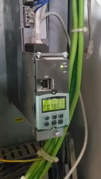
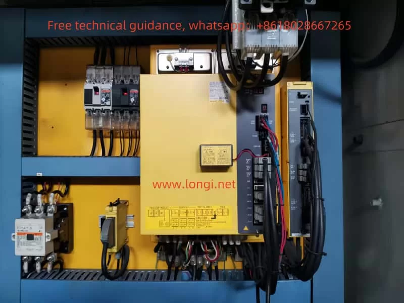
FANUC servo drives, specifically the βISVSP A06B series, are widely used in various automated equipment, providing efficient and precise motor control. However, in practical use, various faults may arise, with one of the most common being the lack of display. A non-functional display is often caused by power issues, control circuit problems, or hardware malfunctions. This article explores the maintenance approach for resolving no display issues in FANUC servo drives, focusing on troubleshooting steps and solutions.

I. Fault Phenomenon: No Display

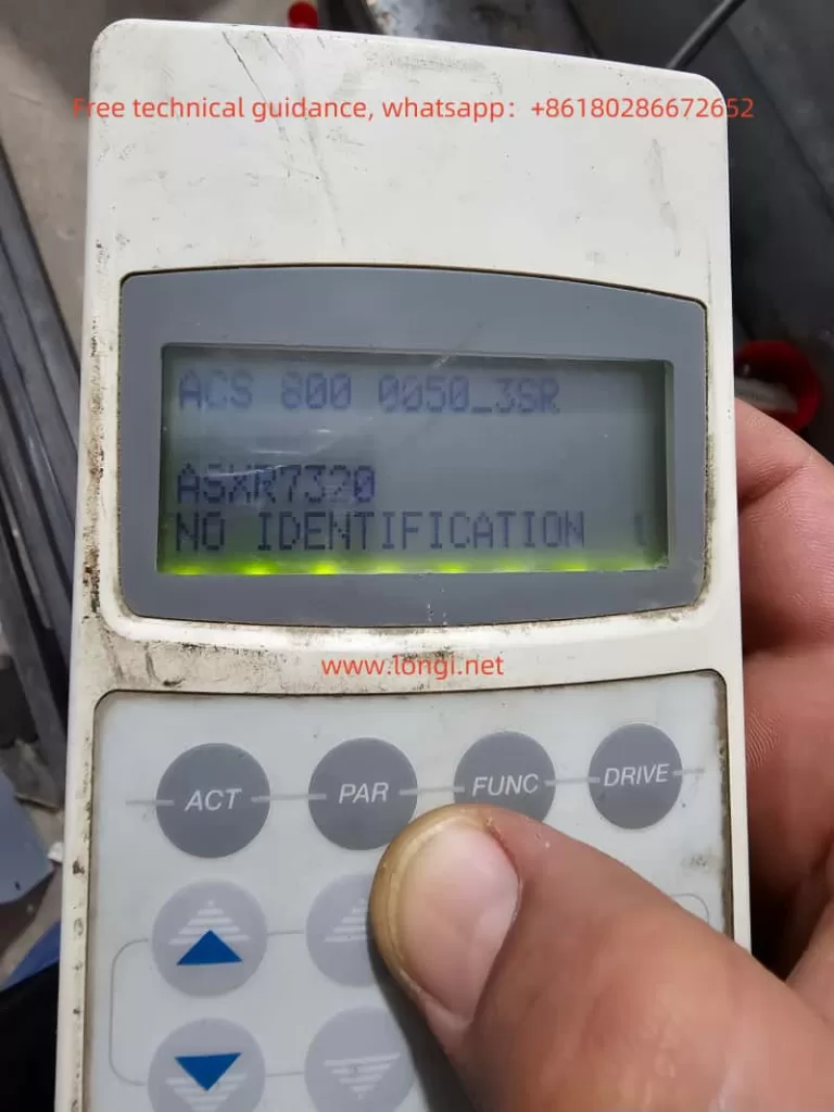
The no display fault in FANUC servo drives refers to a situation where the device powers on, but the panel displays no information. The indicator lights might be completely off, or the screen may be unresponsive, suggesting that there could be problems with the control circuits, display module, or power supply module inside the drive. If not addressed in a timely manner, this issue could prevent the device from starting or executing control instructions, which can negatively impact production efficiency.

II. Troubleshooting Approach

When encountering a no display issue in a servo drive, it’s essential to systematically check the device. Below are the common troubleshooting steps:

1. Check Power Supply Input

The first step is to verify if the power supply to the servo drive is functioning correctly. Power is the foundation for all electronic devices, and any instability or interruption in the power supply can prevent the drive from functioning properly.

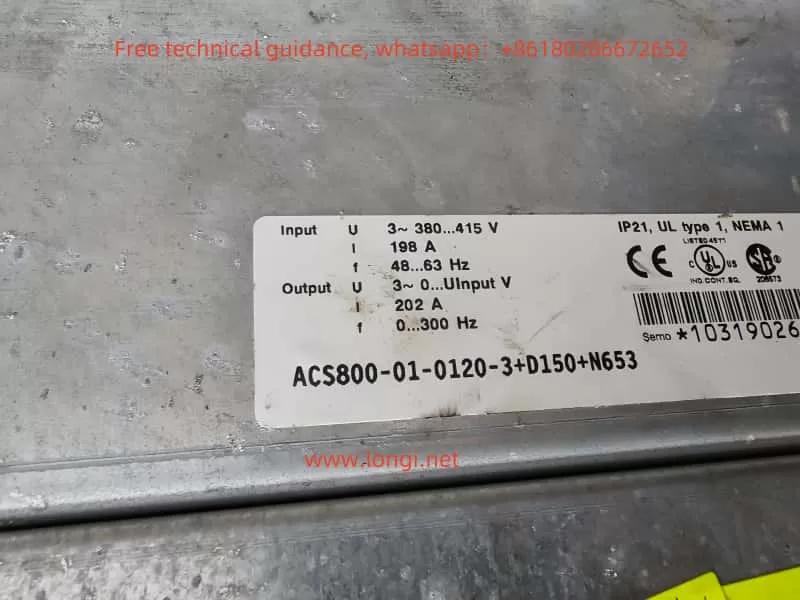
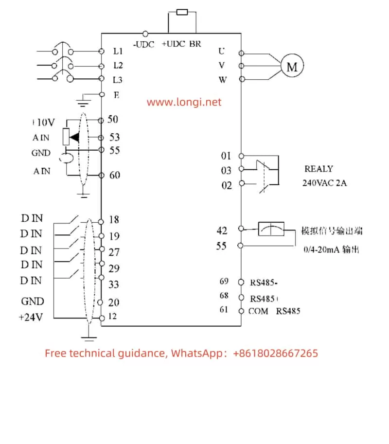
  • Check the Power Voltage: Use a multimeter to check the voltage at the input terminals of the servo drive, confirming that it falls within the specified range. The FANUC servo drive typically requires a three-phase AC input voltage within a certain range.
  • Check Power Connections: Verify that the power supply cables are correctly connected and not damaged or disconnected. Poor power contact can lead to unstable voltage supply, which can result in no display issues.

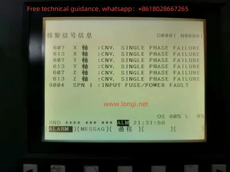
2. Check Fuses and Circuit Breakers

Servo drives are equipped with fuses or circuit breakers to prevent damage from excessive current. If a fuse blows or the circuit breaker trips, the device will fail to operate properly.

  • Check the Fuse: Open the servo drive and inspect the fuses in the power section. If the fuse is blown, replace it with one of the same rating.
  • Check the Circuit Breaker: Some servo drives come with an internal circuit breaker that trips in case of voltage abnormalities or overcurrent. If the circuit breaker has tripped, reset it manually.

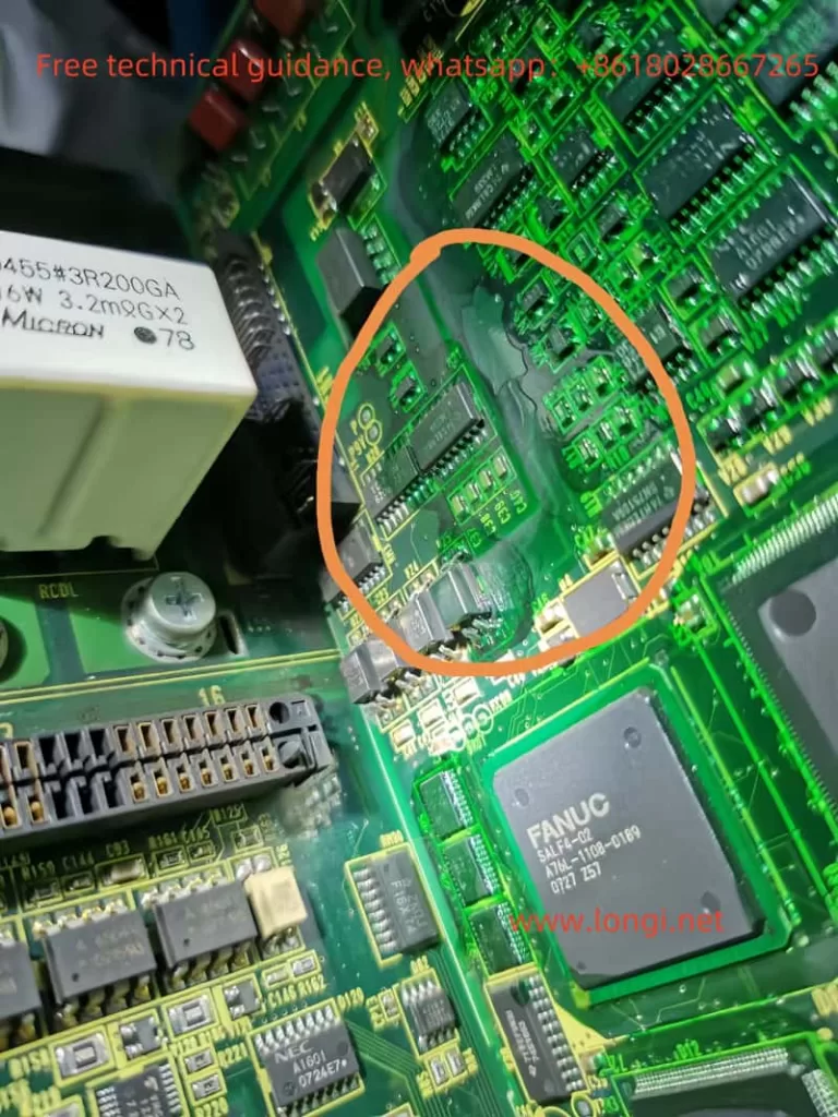
3. Check the Main Control Circuit

If the power supply is fine, the next step is to inspect the servo drive’s main control circuit. The control circuit acts as the brain of the servo drive, and any malfunction in this area could result in a non-responsive display.

  • Check the Control Chip: The control chip is usually located centrally on the circuit board and is responsible for processing input signals and controlling the operation of the drive. Look for signs of overheating, burning, or damage around the chip. Use an oscilloscope or multimeter to check the power supply voltage and signal output of the chip to ensure it’s functioning properly.
  • Check Circuit Connections: The circuit board in the servo drive is connected to various modules via connectors. Check if any connectors are loose or disconnected, as poor connections can prevent signals from transmitting correctly.

4. Check the Display Module and Signal Transmission

The display module is responsible for showing system status information to the operator. If the display module fails, it could lead to a no display situation.

  • Check the Display Screen: Inspect the power supply input terminals and signal transmission lines to the display screen to ensure they are properly connected. If the display module itself is faulty, it may need to be replaced.
  • Check Signal Transmission: If the display module appears intact, the issue could lie with the signal transmission. Inspect the signal lines between the main control board and the display module to ensure that signals are properly transmitted.

5. Check Capacitors and Power Filtering Circuits

Capacitors and filtering circuits help stabilize the voltage supply, especially for high-frequency currents. If the capacitors are damaged, the power supply could become unstable, affecting the drive’s operation.

  • Check the Capacitors: Look for signs of bulging, leakage, or aging in the capacitors. If a capacitor is faulty, it should be replaced with one of the same model.
  • Check the Filtering Circuits: The components in the filtering circuits may also be damaged, which can cause unstable voltage output. Inspect these components and replace them as necessary.

III. Common Fault Analysis and Solutions

1. Unstable Power Supply Leading to No Display

An unstable power supply voltage can prevent the drive from starting properly. In this case, check the stability of the power supply and ensure the voltage is within the specified range. If issues are found with the power supply, it may be necessary to replace the power module or reconnect the power supply.

2. Control Circuit Malfunction

A malfunctioning control circuit can prevent the system from starting or lead to a no display issue. Typically, this fault requires replacing damaged components. Commonly damaged components include control chips, integrated circuits, and resistors.

3. Display Module Failure

If the display module itself is faulty, it could be due to issues with the backlight, circuit board, or the display screen. Inspect the power input terminals and signal transmission lines to confirm the issue. If the display screen is damaged, replacing the display module will likely resolve the problem.

4. Capacitor or Filtering Circuit Issues

Damaged capacitors can cause unstable power, affecting the drive’s operation. Replacing faulty capacitors or repairing the filtering circuits should solve this issue.

IV. Conclusion

The no display issue in FANUC servo drives βISVSP A06B series is typically related to power problems, control circuit failures, or display module malfunctions. Through systematic troubleshooting and careful inspection, the problem can usually be pinpointed and resolved. During maintenance, special attention should be paid to power stability, circuit connections, and the condition of critical components. For more complex issues, professional diagnostic tools may be required, and damaged components should be replaced to restore the device to normal operation. Timely and effective maintenance ensures the long-term stability and performance of FANUC servo drives, helping to maintain production efficiency.