Take advantage of ABB’s ACS510 VSD for seamless multi-pump pressure control. With its advanced PFC application macro, you can effortlessly manage up to 7 pumps while ensuring consistent pressure regulation. This powerful feature eliminates the need for a separate constant pressure water supply controller, simplifying your system design. By implementing the SPFC macro, you can enjoy the added benefit of reducing stress on your pumps and power grid through gentle soft-start sequences. Consider SPFC as an enhanced version of PFC, providing superior control and reliability for your critical applications.
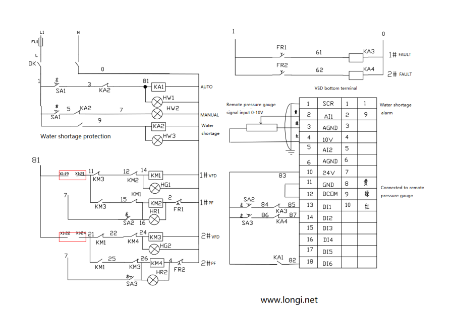
According to your description, DL6 is used for start commands, DL1 and DL2 for PFC control. SA1, SA2, and SA3 are three-position switches, with the middle position as stop. When manually operating at rated frequency, the switch is set to the right, and when the automatic allow signal is present, the switch is set to the left. The connections at 19, 21 and 22, 24 are connected to the relay terminals below the VFD, corresponding to the normally open contacts of RO1 (Relay 1) and RO2 (Relay 2).
The difference between PFC and SPFC:
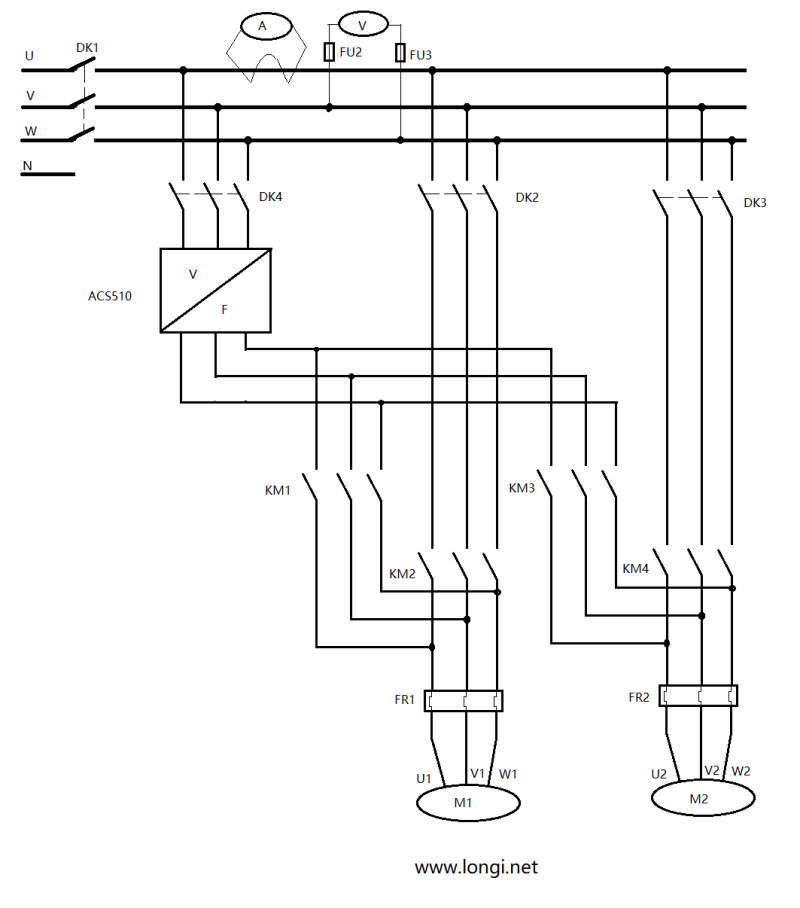
In automatic mode with PFC: When SA2 and SA3 are set to the automatic position and the power is turned on, relay 1 on the inverter engages, which causes KM1 to engage and the motor M1 to start operating at variable frequency. If the frequency reaches the start-up frequency +1, the auxiliary motor is engaged, and relay 2 on the inverter engages, causing KM3 to engage and motor M2 to start operating at rated frequency. With PFC in automatic mode, it is possible to switch pumps at regular intervals.
In automatic mode with SPFC: When SA1 and SA2 are set to the automatic position and the power is turned on, relay 1 on the inverter engages, which causes KM1 to engage and the motor M1 to start operating at variable frequency. When the frequency reaches the start-up frequency +1, relay 1 is first disengaged and then relay 2 is engaged, causing KM4 to engage and motor M2 to start operating at variable frequency. Simultaneously, relay 1 re-engages to cause KM2 to engage and motor M1 to operate at rated frequency. With SPFC in automatic mode, it is not possible to switch pumps at regular intervals.
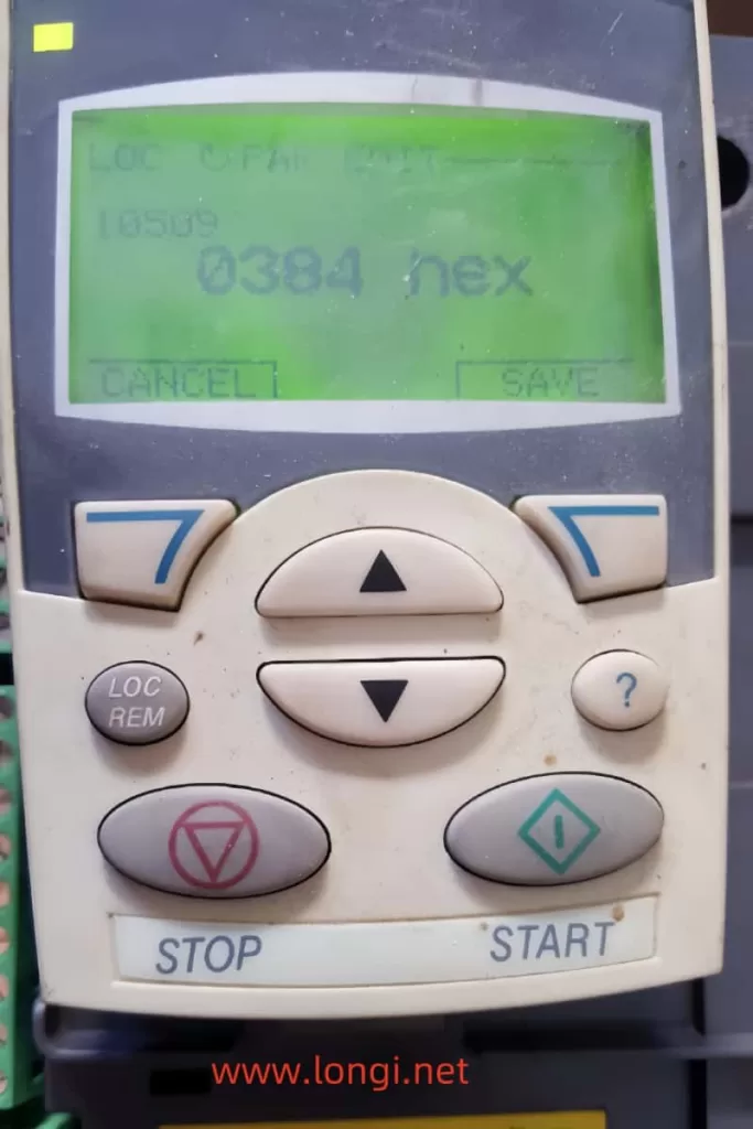
CODE NAME SET VALUE NOTES
9902 APPLIC MACRO 15=SPFC control
1002 EXT2 COMMANDS 6=DI6 VSD startup command
1102 EXT1/EXT2 SEL 7=EXT2
1106 REF2 SELECT 19=PID1OUT After SPFC takes effect, 1106 defaults to 19 and does not require adjustment
1401 RELAY OUTPUT 1 31=PFC control
1402 RELAY OUTPUT 2 31=PFC control
1403 RELAY OUTPUT 3 4=FAULT
1601 RUN ENABLE 6=DI6
2008 MAXIMUM FREQ 50HZ
2202 ACCELER TIME 1 15S Set according to actual situation
2203 DECELER TIME 1 15S Set according to actual situation
3104 AR OVERCURRENT 1=ENABLE
4001 GAIN(PID) 1.5-2
4002 INTEGRATION TIME(PID) 2.5
4009 100% VALUE ” Defines (together with 4008) the scaling Set according to actual situation
applied to the PID controller’s actual values”
4010 SET POINT SEL 0=keypad – Control panel provides reference.
4016 ACT1 INPUT 1=AI1 is ACT1(Remote transmission meter);2=AI2 is ACT1(Pressure sensor)
4022 SLEEP SELECTION 7=INTERNAL
4023 PID SLEEP LEVEL 38HZ Set according to actual situation
4024 PID SLEEP DELAY 30S
4025 WAKE-UP DEV 2.5
8118 AUTOCHNG INTERV 1h
8119 AUTOCHNG LEVEL 85%
8120 INTERLOCKS 1=DI1 Enables the Interlock function
8123 PFC ENABLE 1 = ACTIVE – Enables PFC control
8127 MOTORS 2 After SPFC takes effect, it defaults to 2, and there is no need to adjust the two pumps
The parameters mentioned in this article use SPFC macros, and PFC is also similar, except that the macro parameter is 7.VSDs such as ACS550 and ACS355 should also be able to achieve constant pressure water supply frequency converter control through similar operations. Please refer to their technical manuals for details, or contact us for guidance