Posted on

Root Cause Analysis and Systematic Troubleshooting of ABB ACS800 FF51 Fault (LINE CONV)

1. Introduction

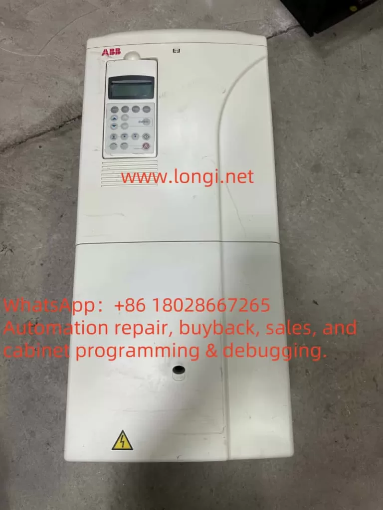
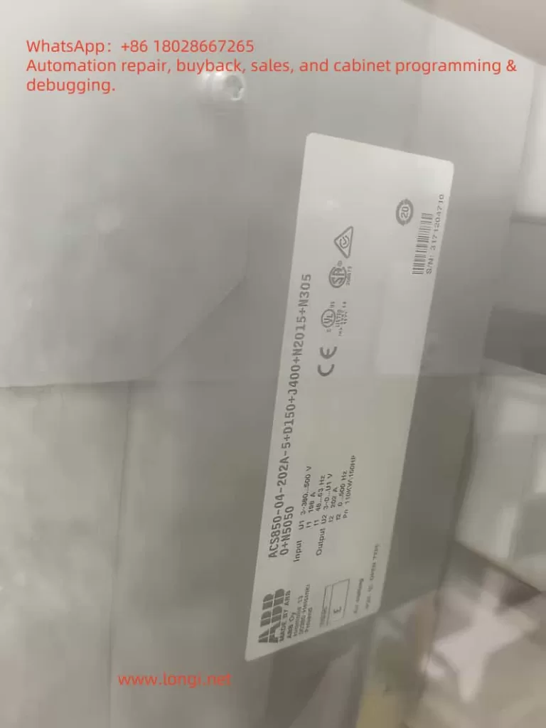
The ABB ACS800 drive series is widely used in metallurgy, mining, chemical plants, marine propulsion, and heavy industrial machinery. Known for its modular architecture and strong control capabilities, the ACS800-11 multidrive system combines line converter units (LCUs) with inverter units (INUs) through a common DC bus to deliver highly efficient variable speed drive and regenerative power control.

During field operation, however, maintenance teams often encounter the FF51 fault code (LINE CONV). This particular code indicates a malfunction on the line-side converter, which is critical because it manages the AC-to-DC conversion and grid interface. Unlike straightforward motor-side faults, FF51 requires engineers to investigate the health and operation of the line converter unit itself.

This article provides a comprehensive analysis of FF51:

  • Theoretical background of the ACS800 multidrive system,
  • Fault triggering mechanism,
  • Common causes and failure modes,
  • Interpretation of wiring diagrams and key inspection points,
  • Step-by-step troubleshooting workflow,
  • Case studies from industrial practice,
  • Preventive measures and maintenance guidelines.

The goal is to present a systematic methodology for resolving FF51 faults, minimizing downtime, and ensuring reliable operation in mission-critical applications.


2. Overview of the ACS800-11 Multidrive System

2.1 Major Components

An ACS800-11 multidrive typically consists of:

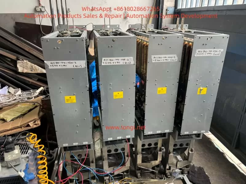
  1. Line Converter Unit (LCU) – Converts incoming AC supply into a stable DC link, often using active front-end IGBT rectifiers for reduced harmonics and energy regeneration.
  2. DC Link Bus – A shared bus that transfers energy between the LCU and multiple inverter units.
  3. Inverter Units (INUs) – Convert DC back into AC with variable voltage and frequency to control motor speed and torque.
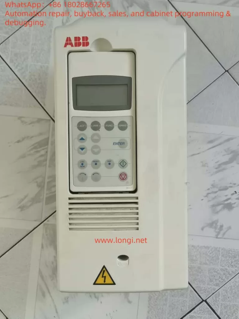
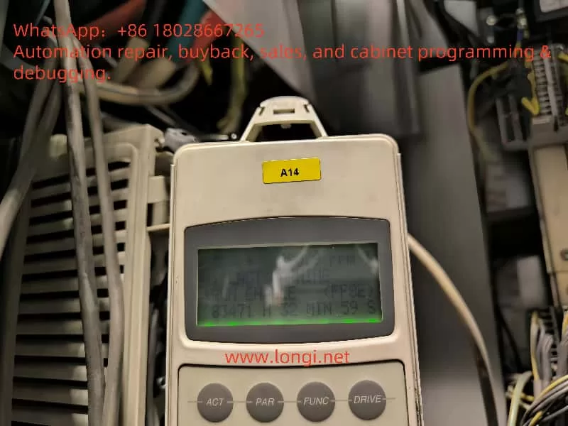
  4. Control and Communication Modules – Including the Rectifier Control Unit (RMCU), Drive Control Panel (CDP), and fiber optic links for communication and monitoring.

2.2 Operating Principle

  • Rectification: The LCU rectifies grid power into DC, while maintaining power factor control and reducing harmonics.
  • Inversion: INUs convert DC into variable AC for motor operation.
  • Regeneration: During braking or load lowering, excess energy is returned to the grid via the LCU.

2.3 Why FF51 is Critical

The FF51 fault (LINE CONV) does not point to a single failed component. Instead, it acts as a system-level alert that something is wrong in the LCU. Engineers must further interrogate the LCU to identify the specific underlying fault, such as overvoltage, undervoltage, or hardware failure.


3. Definition and Triggering of FF51

3.1 Official Description

  • Code: FF51
  • Name: LINE CONV
  • Scope: ACS800-11 multidrive only
  • Meaning: A fault has been detected in the line-side converter. The system disables power transfer and may switch to motor-side supply if configured, while prompting the user to check the LCU.

3.2 Triggering Mechanism

FF51 can be triggered under three main conditions:

  1. Supply anomalies – Grid imbalance, phase loss, voltage sags, or spikes.
  2. Hardware damage – Failed rectifier IGBTs, blown fuses, inductor failure, capacitor degradation.
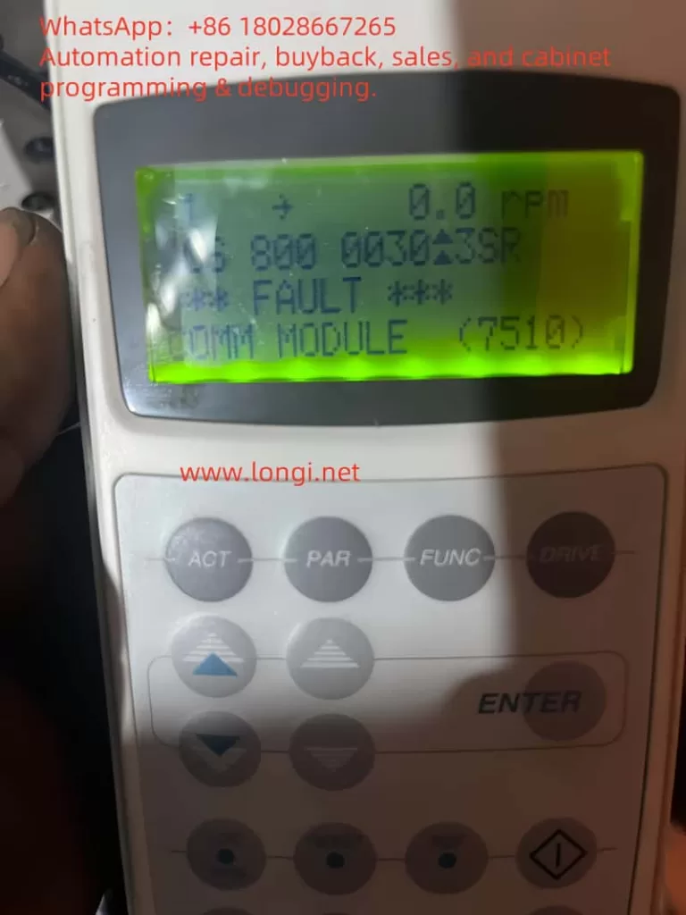
  3. Control/communication issues – Faulty RMCU board, optical fiber disconnection, or loss of auxiliary supply.

3.3 Fault Response

Upon detection:

  • Power transfer through the LCU is interrupted.
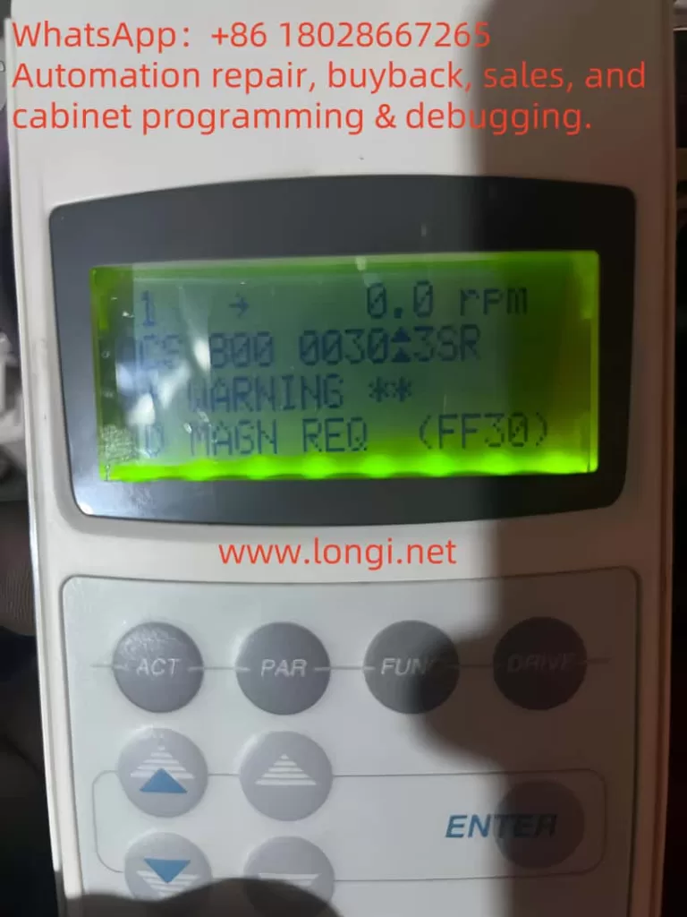
  • The CDP logs and displays FF51.
  • Depending on system design, operation may switch to inverter-side DC link operation, or the system may shut down completely.

4. Root Cause Analysis of FF51

4.1 Supply-Side Factors

  • Grid imbalance exceeding ±10% tolerance.
  • Sudden voltage dips or blackouts.
  • Excessive harmonic distortion.
  • Missing phase at the input supply.

4.2 Hardware Failures

  1. Rectifier Bridge Failures
    • Shorted or open IGBT modules.
    • Diode failure.
    • Leads to unstable DC bus voltage or excessive input current.
  2. Blown Fuses
    • Triggered by short circuits or transient inrush currents.
  3. Inductor/Filter Issues
    • Broken coil windings.
    • Insulation breakdown causing short circuits.
  4. Capacitor Aging
    • Excessive DC bus ripple.
    • Inrush charging issues.

4.3 Control and Signal Issues

  • Faulty RMCU communication (fiber optic disconnect or board failure).
  • Missing auxiliary supplies (+24 VDC, +20 VDC, +10 VDC).
  • Loose terminals or corroded connections leading to signal errors.

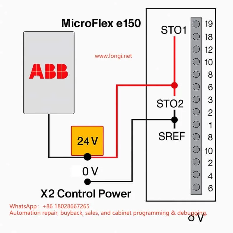
5. Diagram Interpretation and Key Checkpoints

The provided wiring diagrams of ACS800-11 highlight several critical inspection points:

  1. Terminal Blocks (X20 / X25)
    • Distribution of control signals and auxiliary power.
    • Ensure stable +24 VDC and return paths.
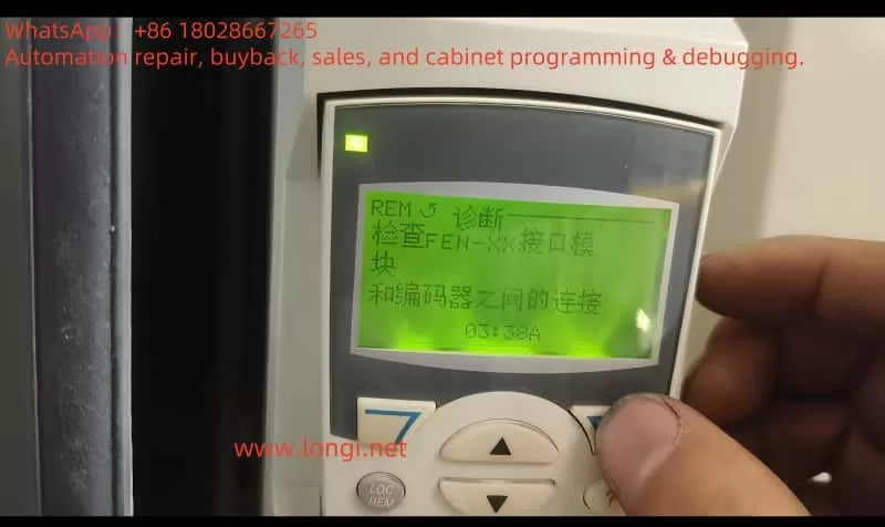
  2. RMCU to INU Fiber Communication
    • Verify optical link continuity and insertion quality.
    • Check signal strength at both ends.
  3. Input Fuses F1/F2/F3
    • Confirm continuity using a multimeter.
    • Match replacement fuses to the specified ratings.
  4. Rectifier Modules (U/V/W → DC+ / DC-)
    • Test for shorted or open devices using diode test mode.
    • Look for phase-specific failures.
  5. Inductor and Busbar Connections
    • Verify tight mechanical connections.
    • Inspect inductance for open circuits or overheating.

6. Step-by-Step Troubleshooting Procedure

A systematic troubleshooting workflow for FF51:

  1. Read Sub-Fault Codes
    • Access the CDP Line Converter menu.
    • Record detailed subcodes (e.g., undervoltage, IGBT fault, overvoltage).
  2. Check Input Supply
    • Measure phase-to-phase voltages.
    • Verify fuses and contactors.
  3. Test Power Components
    • Use a multimeter to test IGBT modules and diodes.
    • Inspect bus capacitors for ESR increase or leakage.
  4. Verify Control and Communication
    • Check optical fiber links.
    • Measure +24 VDC and other auxiliary supplies.
  5. Restart and Monitor
    • Power cycle the system after corrective actions.
    • Monitor whether FF51 reappears.

7. Case Studies from Industry

Case 1: Steel Rolling Mill

A rolling mill experienced recurring FF51 alarms. Analysis showed severe grid imbalance and phase drops. Installation of grid stabilizers and phase monitoring eliminated the issue.

Case 2: Mining Hoist

A mine hoist reported FF51. Investigation revealed a shorted IGBT in the line converter module. Replacement of the rectifier unit restored operation.

Case 3: Chemical Plant Pump

A chemical plant ACS800 system showed FF51 despite a stable grid. The issue was traced to a loose fiber optic link between the RMCU and inverter. Securing the connection solved the problem.


8. Preventive Measures and Maintenance

  1. Power Quality Management
    • Use harmonic filters and reactive power compensation.
    • Avoid frequent voltage dips and disturbances.
  2. Scheduled Component Testing
    • Inspect IGBT modules and DC bus capacitors annually.
    • Monitor ESR and thermal performance.
  3. Signal and Connection Integrity
    • Tighten all terminals periodically.
    • Clean and secure optical connectors.
  4. Data Logging and Predictive Maintenance
    • Maintain operational logs of fault history.
    • Use predictive diagnostics to identify early failure signs.

9. Conclusion

The FF51 fault (LINE CONV) in ABB ACS800-11 multidrive systems is a critical indicator of line converter malfunction. Causes typically fall into three categories: supply anomalies, hardware failures, or control/communication faults.

Effective resolution requires:

  • Detailed inspection of supply voltage and fuses,
  • Testing of rectifier modules and DC bus components,
  • Verification of RMCU communication and auxiliary supplies,
  • Stepwise elimination of potential issues based on wiring diagrams and fault history.

Preventive strategies such as power quality management, regular component checks, and proper maintenance of signal integrity are key to minimizing downtime.

With a structured troubleshooting workflow and proactive maintenance, industries can ensure long-term stability and reliability of their ACS800 multidrive systems.


Posted on

ABB MicroFlex e150 STO Safety Circuit Principle and Practical Wiring Guide

1. Introduction

In modern industrial automation, drive safety functions are an indispensable part of system design. In applications where the motor torque must be stopped quickly and reliably, the STO (Safe Torque Off) function plays a crucial role. The ABB MicroFlex e150 servo drive, as a high-performance multi-purpose servo drive, integrates a dual-channel STO safety input circuit that meets international safety standards. Correctly understanding its principle and wiring method is essential not only for the proper operation of the equipment, but also for the safety of personnel and machinery.

This article, based on official documentation and field experience, will analyze in depth the ABB MicroFlex e150’s STO interface design, working principle, and both bench-test and field wiring schemes.


E10033

2. Overview of the STO Function

2.1 What is STO?

STO (Safe Torque Off) is a safety function used to immediately cut off the drive pulses to the motor, stopping torque production and preventing unintended motion. Key characteristics:

  • Fast response – cuts torque without needing mechanical braking
  • No mechanical wear – electronic action, no brake wear
  • Safe and reliable – compliant with EN ISO 13849-1 and IEC 61800-5-2 safety standards

In the ABB MicroFlex e150, the STO inputs control the IGBT gate drive enable signals for the power output stage. If the drive detects an STO input open, it will instantly remove gate drive signals and shut down the motor torque.


2.2 Dual-channel redundancy design

The MicroFlex e150 uses a dual-channel STO system:

  • STO1: X3:18 (positive) and X3:8 (SREF reference)
  • STO2: X3:19 (positive) and X3:9 (SREF reference)

The two channels are fully independent. If either channel is open, the drive enters the STO state. This redundancy improves fault tolerance and allows higher safety integrity levels.


EXM08X

3. Hardware structure and principle

3.1 Interface layout

According to the ABB hardware manual, the X3 connector is a multifunction digital I/O interface. Relevant pins for STO are:

  • Pin 18 (STO1 +) – channel 1 positive
  • Pin 8 (SREF) – channel 1 reference
  • Pin 19 (STO2 +) – channel 2 positive
  • Pin 9 (SREF) – channel 2 reference

The drive’s control power input is located on the X2 connector (+24 V and 0 V). This same supply also powers the STO input circuits.


3.2 Internal circuit principle

From the manual’s schematic, each STO input includes:

  • A 33 Ω series resistor (current limiting)
  • A 6.8 kΩ resistor (biasing)
  • An optocoupler (TLP281) for isolation
  • Connection to the internal drive ground

When an external 24 V DC is applied between STO+ and SREF, the optocoupler turns on, the channel is detected as “closed,” and the drive is allowed to enable the motor output. If no voltage is present, the drive disables torque output.


MicroFlex e150

4. E10033 fault cause and clearing method

4.1 Cause of the fault

In the manual, E10033 is defined as “Safe Torque Off input active” – in other words, at least one STO channel is open. Typical causes:

  • STO inputs not wired (common during bench testing)
  • Only one channel wired; the other left floating
  • Safety relay or external safety circuit is open
  • Wiring error; SREF not properly connected to control 0 V

4.2 Temporary test wiring

For bench testing or lab environments without a safety circuit, the fault can be cleared by temporary jumpers:

  1. From X2:+24 V, take two wires to X3:18 (STO1+) and X3:19 (STO2+)
  2. From X2:0 V, take two wires to X3:8 (SREF) and X3:9 (SREF)
  3. Both channels now receive 24 V relative to SREF, so the drive sees STO closed
  4. Power up – the E10033 fault disappears and the drive can be enabled

⚠ This is for testing only. In production systems, a proper safety device must be used.


MicroFlexe150 9A

5. Safety wiring in engineering applications

In real installations, the STO channels should be driven by safety-certified control devices such as:

  • Dual-channel safety relays (e.g., Pilz PNOZ)
  • Safety PLCs (e.g., ABB Pluto, Siemens S7-1500F)
  • Emergency stop button + safety relay combinations

5.1 Wiring essentials

  • Two independent channels – STO1 and STO2 each controlled by separate contacts of a safety relay
  • Common reference – SREF pins must be connected to the control power 0 V
  • Shielding & EMC – use twisted shielded pairs for STO signals; ground the shield at one end

5.2 Safety level considerations

According to EN ISO 13849-1, combining dual-channel STO with a safety relay can achieve Performance Level e / SIL3 safety integrity.
Such a setup is widely used in robotic arms, CNC machines, packaging lines, and other equipment needing quick, safe shutdown.


STO

6. Field commissioning tips

  1. Check STO before first power-on – the drive ships with STO enabled; without wiring, it will always fault E10033.
  2. Monitor STO status in software – Mint WorkBench allows real-time monitoring of STO channel states to diagnose wiring or circuit issues.
  3. Test with an external 24 V – during commissioning, a direct 24 V supply can be used to simulate STO closure for verification.
  4. Avoid overvoltage – STO inputs accept only 24 V DC; applying AC or >30 V DC can damage the optocouplers.
  5. Do not mix SREF connections – each SREF must be tied correctly to its channel; leaving them floating or mismatched can cause faults.

WORKBENCH

7. Conclusion

The ABB MicroFlex e150’s STO interface is designed to meet high safety requirements. Dual-channel redundancy ensures that the motor torque can be safely and quickly disabled in critical situations. Whether in a bench test or in a full-scale installation, understanding the STO principle and wiring method is the foundation for both reliable operation and safety compliance.

Key takeaways:

  • Both STO channels must be closed to enable the drive
  • Bench testing can use temporary jumpers, but production must use a compliant safety circuit
  • Proper wiring, shielding, and grounding are vital to avoid nuisance trips
Posted on

Understanding the Status Icon on ABB ACS880 Drive Panel: Meaning of the Arrow and What Its Disappearance Implies

1. Introduction

In modern industrial automation, the ABB ACS880 series drives are widely used for their robust performance and interactive user interface. Among the display elements on the assistant control panel, the small status icon (typically located at the top-left corner of the screen) plays a vital role. This seemingly minor arrow icon conveys essential information about the drive’s operational state and motor rotation direction. Understanding its function—and especially knowing what it means when the icon disappears—can help engineers diagnose issues quickly and operate the system more effectively. This article explores the icon’s significance and the implications of its absence, along with troubleshooting methods.


Status Icon of acs880 panel

2. What Is the Status Icon and What Does It Indicate?

The status icon is a graphical indicator shown in the Home view of the control panel. It provides a quick visual representation of the motor’s rotation direction and the drive’s operational state.

  • Arrow Direction: When the drive is in local control mode, the arrow points clockwise to indicate forward rotation, and counterclockwise to indicate reverse rotation.
  • Running or Stopped: If the motor is not rotating, the icon may show a numeric value:
    • “1” indicates the drive is in a run state but may not be outputting power.
    • “0” indicates the drive is stopped.

The icon may also display animation or flashing based on the drive status:

Icon StatusMeaning
Static IconDrive is stopped, or start command is inhibited
Flashing IconFault condition, or start command is issued but blocked
Rotating AnimationDrive is running—either with reference = 0 or with load

This compact icon is an intuitive status marker and helps operators understand drive conditions at a glance.


3. What Does It Mean When the Status Icon Disappears?

3.1 Most Common Reason: Remote Control Mode

When the status icon disappears from the upper-left corner of the screen, the most common reason is that the drive has been switched from Local control mode to Remote control mode. In this mode:

  • The drive is controlled via I/O terminals or fieldbus (not the panel).
  • The panel will typically display the word “Remote” instead of the icon.

In other words, the disappearance of the icon is normal behavior when the drive is not under panel control.


3.2 Other Possible Causes

Besides control mode change, here are other less common but relevant causes for the missing status icon:

  1. Communication Failure or Access Restriction
    If the control panel loses communication with the drive or if another device locks control, the panel may not retrieve drive status information.
  2. Modified or Hidden Home View Layout
    The Home view can be customized. If the user or service personnel modified the layout and removed the status section, the icon may no longer appear.
  3. Software Errors or Parameter Misconfiguration
    Though rare, software bugs or misconfigured parameters may cause the icon to not render correctly.

4. Troubleshooting the Missing Status Icon

Here are recommended steps to diagnose and resolve the issue if the status icon is missing:

4.1 Check the Control Mode

  • Look at the top-left of the screen: If “Remote” is shown, the drive is under remote control.
  • Press the Loc/Rem button to switch to Local mode.
  • If the status icon reappears, the issue was due to the control mode setting.

4.2 Verify Panel-to-Drive Communication

  • Check cable connections between panel and drive.
  • If using panel bus with multiple drives, verify the correct drive is selected via Options → Select drive.
  • If communication is unstable, use System info or Diagnostics to confirm panel status.

4.3 Reset the Home View Layout

  • Go to Settings → Reset Home View Layout to restore default display.
  • This ensures the status icon area is re-enabled on the screen.

4.4 Restart the Panel or Drive

  • Power cycle the panel or the entire drive.
  • If the issue persists after restart, consider checking firmware version or configuration settings.
  • Contact ABB service support if necessary.

ACS880-01

5. Conclusion and Recommendations

Though small, the status icon is a powerful visual tool for indicating motor status, rotation direction, and whether the drive is operating. When it disappears, the most likely cause is that the drive is no longer in Local control mode.

Summary of Key Points:

  • Normal Condition: The icon should always be visible in Local mode, indicating status and direction.
  • Icon Disappears: Most likely due to Remote mode.
  • Other Issues: Could include communication errors, customized Home view, or software faults.
  • Recovery Tips:
    • Switch to Local mode using the Loc/Rem button.
    • Restore Home layout if necessary.
    • Verify communication and restart if needed.

Posted on

Analysis and Solution for ABB ACS580 Fault 4310 (A4B0): Power Unit Module Temperature Excessive

Introduction

Variable frequency drives (VFDs) like the ABB ACS580 are vital in industrial automation, offering precise control over motor speed and torque for applications such as pumps, fans, and conveyors. These drives enhance efficiency but can encounter faults that disrupt operations. One common issue is fault code 4310, also known as A4B0, which signals that the power unit module temperature has exceeded safe limits. This article explores the causes, mechanisms, troubleshooting steps, and preventive measures for this fault, providing a comprehensive guide for users and maintenance personnel to ensure reliable operation.

4310 FAULT

Understanding Fault 4310 (A4B0)

Fault 4310 (A4B0) in the ABB ACS580 indicates that the temperature of the power unit module, which contains insulated gate bipolar transistors (IGBTs) responsible for converting DC to AC for motor control, has become excessively high. IGBTs generate heat during operation due to switching and conduction losses. When the temperature exceeds a safe threshold (typically 90-100°C, depending on the model), the drive triggers this fault to halt operation and protect internal components from thermal damage. The fault code appears on the control panel, often with auxiliary codes indicating specific issues, such as overheating in the U, V, or W phase, or environmental factors.

Causes of Fault 4310 (A4B0)

Several factors can contribute to the power unit module overheating, including:

  1. High Ambient Temperature: The ACS580 is designed to operate in environments up to 40°C (104°F). If the surrounding temperature exceeds this, the cooling system may struggle to dissipate heat effectively, especially in enclosed or poorly ventilated spaces.
  2. Insufficient Cooling: The drive relies on cooling fans to draw air over heat sinks attached to the power modules. Fan failures due to worn bearings, electrical issues, or blocked airflow paths (e.g., by debris or improper placement) reduce cooling efficiency.
  3. Dust Accumulation: In industrial environments, dust and particulate matter can accumulate on heat sinks, acting as an insulator and hindering heat transfer. This reduces the cooling system’s effectiveness.
  4. Overloading: Operating the drive beyond its rated power capacity causes the IGBTs to generate excessive heat. This can occur if the connected motor or load exceeds the drive’s specifications.
  5. Incorrect Installation: ABB provides specific installation guidelines, including minimum clearance distances for airflow. Installing the drive in a confined space or near heat-generating equipment can trap heat, leading to overheating.

Mechanism of Fault 4310 (A4B0)

The ACS580 is equipped with temperature sensors that continuously monitor the power unit module’s temperature. These sensors are integrated into the drive’s control system, which compares the measured temperature against a predefined limit. If the temperature exceeds this threshold, the drive activates fault 4310 (A4B0) to stop operation, preventing damage to the IGBTs and other components. The fault may be accompanied by auxiliary codes that pinpoint the issue, such as specific phase overheating (U, V, or W), environmental temperature issues, or internal component failures. This protective mechanism ensures the drive’s longevity and reliability by addressing thermal risks promptly.

Troubleshooting and Solutions

To resolve fault 4310 (A4B0), follow these systematic steps:

  1. Check Ambient Temperature: Measure the temperature near the drive using a reliable thermometer. Ensure it is within the 0-40°C range specified for the ACS580. If the temperature is too high, improve ventilation by adding fans or air conditioning, or relocate the drive to a cooler area.
  2. Inspect Cooling Fans: With the drive powered off, check all cooling fans for proper operation. Look for signs of damage, loose connections, or worn bearings. Listen for unusual noises indicating fan issues. Replace faulty fans with ABB-approved components and verify that the fan direction supports proper airflow.
  3. Clear Airflow Paths: Ensure that air intake and exhaust vents are free from obstructions such as cable bundles, dust filters, or other objects. Remove any covers or panels that restrict airflow and reposition items as needed.
  4. Clean Heat Sinks: Disconnect the drive from power and use compressed air or a soft brush to remove dust and debris from the heat sinks. Avoid using liquids that could leave residues or damage components. Ensure the heat sinks are clean to maximize heat transfer.
  5. Verify Load: Compare the drive’s rated power (listed on its nameplate) with the motor’s specifications and the actual load. If the load exceeds the drive’s capacity, consider reducing the load or upgrading to a higher-capacity drive model.
  6. Review Installation: Consult the ABB ACS580 installation manual to confirm that the drive is mounted correctly. Ensure there is at least 100 mm (4 inches) of clearance on all sides for airflow. Verify that the drive is not exposed to direct sunlight or other heat sources.
  7. Reset the Drive: After addressing the above issues, reset the drive by cycling power or using the reset button on the control panel. Monitor the drive’s operation to ensure the fault does not recur. Check the event log for any additional diagnostic information.
ACS580

Troubleshooting Steps Table

StepActionNotes
Check Ambient TemperatureMeasure temperature near the driveEnsure within 0-40°C; improve ventilation if needed
Inspect Cooling FansCheck for operation, damage, or noiseReplace faulty fans; confirm correct airflow direction
Clear Airflow PathsRemove obstructions from ventsEnsure no cables or debris block intake/exhaust
Clean Heat SinksUse compressed air or brush to cleanPower off drive; avoid liquids
Verify LoadCompare drive and motor ratingsReduce load or upgrade drive if necessary
Review InstallationCheck clearance and placementEnsure 100 mm clearance; avoid heat sources
Reset DriveCycle power or use reset buttonMonitor for fault recurrence

Preventive Measures

To minimize the risk of fault 4310 (A4B0), implement these preventive strategies:

  1. Regular Maintenance Schedule: Establish a maintenance routine, inspecting and cleaning the cooling system every 6-12 months, depending on the environment’s dust levels. Regular checks prevent dust buildup and ensure fan reliability.
  2. Temperature Monitoring: Utilize the ACS580’s built-in temperature monitoring features (accessible via parameters like 04.11-04.13) to track temperature trends. Set alarms to alert personnel if temperatures approach critical levels, enabling early intervention.
  3. Load Management: Design systems with adequate headroom for peak loads. Avoid operating the drive at or near its maximum capacity for extended periods. Use energy-saving modes or adjust parameters to optimize performance for variable loads.
  4. Proper Installation Practices: Adhere to ABB’s installation guidelines, ensuring proper mounting, electrical connections, and grounding. Maintain specified clearance distances to support airflow and prevent heat buildup.
  5. Environmental Control: In harsh environments (e.g., dusty or hot locations), use NEMA-rated enclosures and maintain air filters. In high-temperature settings, consider additional cooling solutions like heat exchangers or air conditioning.

Preventive Measures Table

MeasureActionFrequency
Regular MaintenanceInspect and clean cooling systemEvery 6-12 months
Temperature MonitoringTrack temperature trends via parametersWeekly or monthly
Load ManagementEnsure load matches drive capacityDuring system design
Proper InstallationFollow ABB guidelines for mountingDuring installation
Environmental ControlUse enclosures, filters, or coolingAs needed per environment

Conclusion

Fault 4310 (A4B0) in the ABB ACS580, indicating excessive power unit module temperature, is a critical issue that demands prompt attention to prevent damage to the drive. By understanding its causes—such as high ambient temperatures, cooling failures, dust accumulation, overloading, or improper installation—users can follow systematic troubleshooting steps to resolve the issue. Preventive measures, including regular maintenance, temperature monitoring, load management, and proper installation, are essential for minimizing the risk of recurrence. Familiarity with the drive’s documentation, such as the user manual and fault tracing guide, and ongoing training for maintenance personnel further enhance operational reliability. By addressing this fault effectively, users can ensure the ACS580 operates efficiently, supporting uninterrupted industrial processes.

Posted on

In-Depth Analysis of ACS880 Fault 9081 “External Fault 1”: Causes, Solutions, and Prevention Strategies

Introduction

The ABB ACS880 series of variable frequency drives (VFDs) is a high-performance solution widely utilized in industrial automation for motor control, energy optimization, and process automation. Renowned for its reliability and flexibility, it is a preferred choice across various industries. However, during operation, VFDs may encounter fault alarms triggered by internal or external factors, with fault code 9081—”External Fault 1″—being one of the more frequent issues. When this fault occurs, the VFD typically halts operation, leading to production interruptions, making swift problem identification and resolution critical.

This article draws on the ACS880 Firmware Manual (version 3AUG0509 005, released August 1, 2013) and the fault details you provided to conduct an in-depth analysis of fault 9081. It explores its causes, impacts on the system, and offers detailed troubleshooting steps, solutions, and preventive recommendations. Our goal is to equip you with a thorough understanding of this fault, enabling you to restore normal operation efficiently in practical scenarios.


FAULT 9081

1. Definition and Background of Fault 9081

According to the “Fault Tracing” section on page 299 of the ACS880 Firmware Manual, fault code 9081 is defined as “External Fault 1.” This is a protective fault triggered by an external input signal, indicating that the VFD has received a fault signal via a digital input (DI) terminal or fieldbus, suggesting a potential risk to the system. The manual specifies that this fault is closely tied to parameter 31.01 (External Fault 1 Signal Source), which allows users to designate the source of the fault signal, such as a specific digital input (DI1 to DI6) or a designated bit in the fieldbus control word.

Based on the fault description you provided, the ACS880 control panel displays “Fault 9081 AUX Code 0000 0000” with “External Fault 1” noted. The auxiliary code (AUX Code) is all zeros, indicating no additional sub-fault details are available. The panel also shows an operating speed of 1420 rpm, a timestamp of 15:09:31, a “Remote” status, and an illuminated red fault indicator, confirming the device has entered a stopped state. This information serves as a valuable starting point for further analysis.

The External Fault 1 feature is designed to protect the VFD and its connected load from external anomalies. By configuring parameters, users can link the status of external devices (e.g., sensor alarms, PLC signals) to the VFD’s protective mechanisms. However, this also means that the root cause of fault 9081 may lie outside the VFD itself, in the external environment or configuration.


2. Possible Causes of Fault 9081

Drawing from the manual and real-world industrial scenarios, the causes of fault 9081 can be categorized as follows:

2.1 External Device Malfunction

The most common cause of External Fault 1 is a failure in an external device connected to the VFD. For instance, a temperature sensor detecting motor overheating, a pressure switch triggered by system overpressure, or an emergency stop button being inadvertently pressed could send a high-level signal via a digital input (e.g., DI1) to trigger the fault.

2.2 Wiring Issues

Faulty wiring at the digital input terminals is another frequent culprit. Loose, broken, or short-circuited connections can disrupt signal transmission. For example, damage to the DI1 signal line or poor contact might lead the VFD to misinterpret the state as a fault. Additionally, unshielded signal cables may be susceptible to electromagnetic interference (EMI), causing signal jitter or false triggers.

2.3 Incorrect Parameter Settings

Parameter 31.01 defines the signal source for External Fault 1. Misconfiguration, such as assigning an unused terminal (e.g., DI2) as the source or failing to match the external device’s logic state (high or low), can result in erroneous alarms. For fieldbus-triggered faults, parameters 50.01 (FBA A Enable) and 51.27 (FBA Parameter Update) must also be correctly set.

2.4 External Power or Control System Issues

Instability in the external device’s power supply or anomalies in the control logic can also trigger the fault. For example, a programming error in a PLC might cause it to send an unintended fault signal to the VFD, or voltage fluctuations in the external power supply could affect sensor operation.

2.5 Environmental Factors

Harsh industrial environments (e.g., high temperatures, humidity, dust) can impact the reliability of external devices or wiring. For instance, a sensor might malfunction under high heat, or corroded terminal connections could fail, triggering External Fault 1.


ACS880

3. Impact of Fault 9081

Once fault 9081 is triggered, the VFD executes a default protective action based on parameter 31.11 (Fault Reset Selection), typically an immediate shutdown. This stops the motor, disrupting production line continuity and efficiency. If left unresolved, the fault may lead to further issues:

  • Production Downtime: Line stoppages can result in significant economic losses, particularly in continuous production settings.
  • Safety Risks to Equipment: Failure to identify and address the external fault could lead to more severe system damage.
  • Increased Maintenance Costs: Recurring faults may require additional troubleshooting and repair time.

Thus, promptly and accurately resolving fault 9081 is essential.


4. Troubleshooting Steps

To effectively address fault 9081, follow these systematic troubleshooting steps:

4.1 Review Control Panel Information and Event Log

Begin by recording the fault details on the control panel (time, speed, status, etc.). Then, access the “Event Log” menu via the control panel or Drive Composer PC tool to review detailed fault logs. Page 300 of the manual notes that the event log stores the fault occurrence time and other parameters, aiding in identifying the trigger conditions.

4.2 Verify Parameter 31.01 Settings

Navigate to the parameter settings menu and check the configuration of parameter 31.01:

  • If set to a digital input (e.g., DI1), note the terminal and inspect its wiring and signal state.
  • If set to a fieldbus signal, verify the communication status and control word configuration.

4.3 Inspect External Devices and Wiring

Based on parameter 31.01, examine the corresponding external device and wiring:

  • Use a multimeter to measure the voltage at the digital input terminal, confirming whether it is high (typically 24V indicating a fault state).
  • Check for secure connections, ruling out looseness, breaks, or shorts.
  • Ensure signal cables are properly shielded to avoid electromagnetic interference.

4.4 Investigate External Control Systems

For fieldbus-triggered faults, inspect the PLC or upper-level controller’s program logic to ensure no erroneous fault signals are sent. Verify that communication parameters (e.g., 50.01 and 51.27) are correctly configured.

4.5 Mitigate Environmental Effects

Assess the operating environment for issues like high temperature, humidity, or dust. If conditions are adverse, implement protective measures such as installing covers or improving ventilation.

4.6 Review Historical Fault Records

Check parameter group 04 (Warnings and Faults) for the current fault (04.01) and historical records (04.02 to 04.06) to determine if the fault recurs or is linked to other issues.


5. Resolution Methods

Based on the troubleshooting results, apply the following targeted solutions:

5.1 Repair External Devices

If a sensor or switch is faulty (e.g., triggered by overheating), repair or replace the defective component to restore normal signal output.

5.2 Address Wiring Problems

Re-secure loose connections or replace damaged cables. If interference is present, use shielded cables and ensure proper grounding.

5.3 Adjust Parameter Settings

If parameter 31.01 is misconfigured, adjust it to the correct signal source or temporarily disable the External Fault function (set to “Not Used”) to isolate the issue. For fieldbus users, ensure parameters 50.01 and 51.27 are correctly set before restarting the device.

5.4 Fault Reset and Testing

Per page 299 of the manual, fault reset can be performed via the control panel, digital input, or fieldbus. Press the “Reset” key on the control panel or configure parameter 31.11 for automatic reset. After resetting, restart the VFD and monitor its operation.

5.5 Seek Technical Support

If the issue persists, page 349 of the manual recommends contacting ABB technical support. Provide the device model (ACS880), firmware version (3AUG0509 005), and fault code (9081) for professional assistance.


6. Prevention Measures and Long-Term Maintenance Recommendations

To prevent recurrence of fault 9081, consider the following preventive actions:

6.1 Regular Inspection and Maintenance

Establish a maintenance schedule to periodically check wiring terminals and external device conditions, preventing aging or damage.

6.2 Optimize Parameter Configuration

Document all parameter settings during commissioning, ensuring that 31.01 and related parameters align with the application to avoid misconfiguration.

6.3 Improve Operating Environment

Maintain suitable temperature and humidity conditions for equipment operation, reducing environmental impacts on external devices.

6.4 Enhance System Monitoring

Use Drive Composer tools or fieldbus for real-time monitoring of VFD status, enabling early detection of anomalies.

6.5 Train Operating Personnel

Provide training on ACS880 operation and fault handling to enhance staff responsiveness.


7. Conclusion

ACS880 fault 9081 “External Fault 1” is a common externally triggered fault, often caused by external device malfunctions, wiring issues, parameter errors, or environmental factors. By reviewing control panel data, parameter settings, wiring, and external devices, users can quickly pinpoint the root cause and resolve it through repairs, adjustments, or resets. Regular maintenance and optimization measures can significantly reduce fault occurrences, ensuring long-term equipment stability.

The ABB ACS880 VFD is celebrated for its efficiency and reliability, and effectively managing fault 9081 not only restores production but also maximizes its value in industrial automation. For complex cases, seeking timely support from ABB is a wise decision. We hope this article’s analysis and recommendations provide practical guidance to enhance your equipment management and production efficiency.

Posted on

Analysis and Troubleshooting of ABB ACS510 VFD Fault F0022 – Supply Phase Missing

1. Overview of the Fault

In industrial automation systems, the ABB ACS510 series VFD is commonly used to control the speed of 3-phase induction motors such as fans, pumps, and compressors. However, in some startup or operating conditions, users may encounter the following fault message on the control panel:

Display: F0022
Fault Type: SUPPLY PHASE (Phase Missing)

This fault is a protective response by the VFD, indicating an abnormality in the input power supply. According to ABB documentation and field service experience, F0022 means that the ripple voltage on the internal DC bus is too high—usually caused by a missing input phase or a blown input fuse.


F0022

2. Root Cause Analysis of F0022

2.1 Nature of Supply Phase Missing

A 3-phase VFD relies on a stable three-phase AC input (U1-V1-W1) to convert into DC voltage through a rectifier bridge. If any one phase is lost or unbalanced, the resulting DC voltage will exhibit abnormal ripple levels.

⚠️ The ACS510 has internal monitoring circuits that detect high DC ripple voltage and trigger F0022 to protect the drive circuitry.

2.2 Common Causes

  • Blown input fuse on one phase;
  • Loose or oxidized input terminal connections;
  • Wiring errors or damaged input cables;
  • Phase loss due to upstream switchgear failure (e.g., contactors or circuit breakers);
  • Severe voltage imbalance in the power supply;
  • Non-simultaneous tripping of breakers causing a single-phase dropout.

3. Step-by-Step Troubleshooting for F0022

Follow these steps systematically to identify and fix the F0022 fault:

Step 1: Check for Actual Phase Loss

Use a multimeter or phase sequence meter to measure voltage between U1-V1-W1 on the drive input:

  • All three phase-to-phase voltages should read within rated limits (typically 380V ±10%);
  • Any phase showing zero or very low voltage confirms a missing phase.

Step 2: Inspect Fuses

Open the power distribution panel and:

  • Check if one of the fuses is open/blown;
  • Test with a multimeter for continuity across each fuse;
  • Replace faulty fuses with the correct type and current rating.

Step 3: Check Terminal Connections

  • Ensure the terminal screws at U1/V1/W1 are tight;
  • Remove any oxidized or burned wires and reconnect properly;
  • Verify copper wire strands are not damaged or frayed.

Step 4: Verify Upstream Circuit Breakers or Contactors

  • Inspect whether one contact is worn or not engaging properly;
  • Replace defective contactors or breakers as needed.

Step 5: Check for Voltage Imbalance

  • Even if all phases are present, large voltage differences can trigger F0022;
  • Measure all three phases—any deviation beyond 10% is problematic;
  • If imbalance is observed, investigate upstream transformer or supply source.

ACS510

4. Preventive Measures for F0022

To prevent recurrence of this fault, consider the following strategies:

4.1 Use Proper Fuses and Breakers

  • Use appropriately rated fuses with fast-acting response;
  • Avoid low-quality circuit breakers with uneven trip behavior;
  • All three phases should be protected with identical devices.

4.2 Add Phase Loss Protection Relay

Install a phase monitoring relay before the VFD input to shut down the system if a phase loss or imbalance is detected.

4.3 Perform Routine Terminal Maintenance

  • Periodically check for loose or oxidized connections;
  • Retorque terminal screws according to the drive’s manual;
  • Re-terminate aged or discolored wires.

4.4 Stabilize the Power Supply

  • Use voltage regulators if power quality is poor;
  • For large-scale systems, consider using isolation transformers or UPS systems to ensure voltage stability.

5. Fault Reset and Drive Recovery

After eliminating the cause of the F0022 fault:

  1. Power down the drive and wait at least 5 minutes (for DC bus capacitors to discharge);
  2. Confirm that all input phases are present and balanced;
  3. Power on the drive and check if the fault is cleared;
  4. Press the RESET or STOP key to reset the fault;
  5. Resume normal operation as needed.

6. Conclusion

The F0022 “Supply Phase Missing” error in ABB ACS510 drives is a common input power issue indicating one or more phase anomalies. The built-in protection mechanism helps safeguard the VFD and motor from damage.

By understanding the electrical causes and following a structured diagnostic approach, maintenance personnel can quickly resolve this issue. Regular inspections, proper component selection, and proactive maintenance of power supply infrastructure are key to preventing such faults and ensuring stable long-term operation of the drive system.


Posted on

Comprehensive Guide to Resolving the FF30 Warning “ID MAGN REQ” for ABB ACS800 Inverters

Introduction: Overview of ABB ACS800 Inverters

The ABB ACS800 series of inverters are high-performance industrial devices widely used in manufacturing, mining, water treatment, and other industries. Their core advantage lies in Direct Torque Control (DTC) technology, which enables precise speed and torque control, making them suitable for various complex applications. However, during operation, users may encounter the FF30 warning “ID MAGN REQ,” a common prompt indicating the need for motor identification and magnetization. This article delves into the meaning, causes, and solutions for the FF30 warning, providing detailed operational steps to help users resolve the issue promptly.

WARNING FF30

Meaning of the FF30 Warning “ID MAGN REQ”

The FF30 warning “ID MAGN REQ” indicates that the inverter needs to identify and magnetize the connected motor. Motor identification is a process where the inverter measures the motor’s electrical characteristics (such as resistance and inductance) to establish an accurate model. This model is crucial for DTC control, ensuring efficient and precise motor operation.

The warning typically appears in the following scenarios:

  • Initial Startup: After entering motor data in parameter group 99 (Startup Data), the inverter prompts for identification.
  • Motor Switching: When using user macros to switch between different motors, the inverter requires re-identification of the new motor.

According to the manual, the FF30 warning is a normal part of the startup process, prompting the user to select an identification method: ID Magnetisation or ID Run.

Importance of Motor Identification

Motor identification plays a vital role in inverter operation with the following key functions:

FunctionDescription
Precise ControlEnsures the inverter adjusts control parameters based on the motor’s actual characteristics, achieving accurate speed and torque control.
Efficient OperationOptimizes motor efficiency, reducing energy consumption.
Motor ProtectionSets appropriate protection limits to prevent overcurrent, overheating, and other faults, extending motor life.
Support for Special ApplicationsEnables stable performance in applications requiring zero-speed operation or high torque without speed feedback.

Motor identification is crucial for ensuring system performance and reliability, especially in ACS800 inverters using DTC control.

Possible Causes of the FF30 Warning

The FF30 warning may be triggered by the following reasons:

  • Incomplete Motor IdentificationID Magnetisation or ID Run not performed after initial startup or motor switching.
  • Incorrect Motor Parameters: Motor data in parameter group 99 (such as rated voltage, current, frequency) does not match the motor nameplate.
  • Wiring Issues: Loose or damaged connections between the motor and the inverter.
  • User Macro Switching: Re-identification required after switching user macros in multi-motor applications.
ACS800

Detailed Steps to Resolve the FF30 Warning

Below are the two primary methods for resolving the FF30 warning: ID Magnetisation and ID Run, along with handling multi-motor scenarios using user macros.

Method 1: ID Magnetisation (Motor Magnetization Identification)

Overview: ID Magnetisation is the process of magnetizing the motor at zero speed, lasting 20–60 seconds, suitable for most applications. It is automatically performed during the inverter’s initial startup.

Operational Steps:

  1. Check Motor Parameters:
    • 99.04: Motor rated voltage
    • 99.07: Motor rated current
    • 99.06: Motor rated frequency
    • 99.08: Motor rated power
    • If parameters are incorrect, adjust and save.
    Enter parameter group 99 and verify that the following parameters match the motor nameplate:
  2. Switch to Local Control Mode:
    • Press the LOC/REM key on the control panel until the display shows “L” (Local Control Mode).
  3. Initiate Magnetization Identification:
    • Press the Start key; the inverter begins magnetizing the motor.
    • The process lasts 20–60 seconds, during which the display may show relevant warnings.
  4. Confirm Completion:
    • After identification, the display shows “ID DONE,” and the FF30 warning disappears.

Method 2: ID Run (Motor Running Identification)

Overview: ID Run is a more advanced identification method suitable for applications requiring high-precision control, such as zero-speed operation or high torque without speed feedback. ID Run comes in two types:

  • STANDARD ID Run: Requires the drive mechanism to be disconnected from the motor, allowing the motor to run freely.
  • REDUCED ID Run: Suitable for scenarios where the drive mechanism cannot be disconnected, with slightly lower accuracy.

Operational Steps:

  1. Check Prerequisites:
    • Refer to the ABB ACS800 firmware manual to ensure that ID Run parameter requirements (such as motor stoppage, load conditions) are met.
  2. Set Parameter 99.10:
    • STANDARD: For scenarios where the load can be disconnected.
    • REDUCED: For scenarios where the load cannot be disconnected.
    Enter parameter group 99 and set 99.10 to “STANDARD” or “REDUCED”.
  3. Switch to Local Control Mode:
    • Press the LOC/REM key to display “L”.
  4. Initiate ID Run:
    • Press the Start key; the inverter begins running identification.
    • The display may show warnings such as “MOTOR STARTS” or “ID RUN”.
  5. Confirm Completion:
    • After identification, the display shows “ID DONE,” and the FF30 warning disappears.

Method 3: Handling Multi-Motor Applications with User Macros

In multi-motor applications, user macros can store parameters for different motors, simplifying the switching process.

Operational Steps:

  1. Save Motor Parameters:
    • After completing identification for one motor, set parameter 99.02 to “USER 1 SAVE” or “USER 2 SAVE” to save the parameters.
    • The saving process takes 20–60 seconds.
  2. Switch Motors:
    • Perform identification (ID Magnetisation or ID Run) for the new motor.
    • Save the new motor parameters to another user macro slot.
  3. Load Parameters:
    • Load the corresponding motor parameters by setting 99.02 to “USER 1 LOAD” or “USER 2 LOAD”.
    • Loading may trigger the FF30 warning again, requiring re-identification.

Troubleshooting and Precautions

If the FF30 warning persists, try the following troubleshooting steps:

IssueTroubleshooting Method
Incorrect Motor ParametersRecheck parameter group 99 to ensure it matches the motor nameplate.
Wiring IssuesInspect the cable between the motor and the inverter to ensure connections are secure and undamaged.
Transient FaultTurn off the inverter power, wait a few minutes, and restart.
Firmware IssuesCheck for available firmware updates on the ABB official website.
Complex Application ScenariosContact ABB technical support, providing the inverter model, firmware version, and application details.

Precautions:

  • Always follow electrical safety norms; disconnect power before checking wiring.
  • Ensure the motor and load are in a safe state when performing ID Run.
  • Confirm parameter settings are correct before saving user macros to avoid overwriting important data.

Conclusion

The FF30 warning “ID MAGN REQ” is a common prompt during the normal startup or motor switching process of ABB ACS800 inverters. By performing ID Magnetisation or ID Run, users can quickly resolve the warning, ensuring optimal performance of the inverter and motor. Motor identification not only eliminates the warning but also optimizes control precision, efficiency, and equipment protection. In multi-motor applications, user macros provide a convenient switching solution. If the issue persists, referring to the official manual or contacting ABB support is advisable.

By correctly understanding and addressing the FF30 warning, users can fully leverage the potential of the ACS800 inverter, providing stable and efficient power support for industrial applications.

Posted on

ACS800 Inverter Fault Code 7510: Causes, Diagnosis, and Solutions

Introduction

The ABB ACS800 series inverters are widely used in industrial control applications, providing reliable AC drive solutions for various conditions, including induction and synchronous motor control. Known for their high power density, advanced harmonic suppression, extensive programmability, and modular design, the ACS800 series excels in industries such as process manufacturing, metal processing, mining, cement production, power generation, chemicals, oil and gas, and even special applications like offshore supply vessels. However, in practical use, the ACS800 inverters may encounter faults, with fault code 7510 being a common communication-related issue. This article provides a comprehensive exploration of fault code 7510, including its meaning, potential causes, diagnostic steps, solutions, and preventive measures to guide users effectively.

fault 7510

Overview of the ACS800 Inverter

The ACS800 series from ABB is a high-performance AC drive designed to meet the needs of a wide range of applications, from small equipment to large industrial systems. Its key features include:

  • High Power Density: Delivers high output power in a compact form, ideal for space-constrained environments.
  • Harmonic Suppression: Utilizes advanced technology to reduce harmonic interference, enhancing power quality.
  • Extensive Programmability: Offers a rich set of parameters and control options for customized applications.
  • Modular Design: Facilitates easy installation, maintenance, and upgrades, reducing operational costs.

The ACS800 inverter is commonly deployed in scenarios requiring precise motor control, such as assembly lines, pump stations, and fan systems. However, communication issues remain a potential challenge, with fault code 7510 being a notable example.

Meaning of Fault Code 7510

In the ACS800 inverter, fault code 7510 typically indicates a “COMM MODULE FAULT.” This fault suggests a periodic loss of communication between the inverter and its main controller, such as a PLC or DCS. Such a disruption can prevent the inverter from receiving control commands or transmitting status updates, severely affecting system operation.

According to official documentation, the 7510 fault is associated with the communication module and is often triggered by programmable fault functions (parameters 30.18 and 30.19). The communication module serves as the bridge between the inverter and external control systems, handling data exchange and synchronization. Any malfunction in this module can compromise the entire system’s performance.

Analysis of Potential Causes

Fault code 7510 can stem from various factors. Below is a detailed analysis of common causes:

CategorySpecific IssueDescription
Communication Connection IssuesDamaged or loose cablesPhysical damage, aging, or poor connections can interrupt signals.
Excessive cable lengthCable length exceeding protocol specifications (e.g., Modbus max of 1200 meters) may cause signal loss.
Poor connector contactImproperly installed or corroded connectors.
Parameter Setting ErrorsMismatched communication protocolInconsistent settings (e.g., baud rate, data bits, stop bits) with the main controller.
Address conflictsInverter address clashes with other devices in the system.
Improper timeout settingsToo short a timeout period may trigger faults under network load.
Fieldbus Configuration ErrorsIncorrect configuration fileErrors in the fieldbus configuration file (e.g., GSD file).
Termination resistor issuesMissing or incorrect termination resistors causing signal reflection.
Fieldbus power problemsUnstable or interrupted fieldbus power supply.
Main Controller IssuesConfiguration errorsIncorrect main controller setup unable to recognize the inverter.
Software incompatibilityMismatched software versions between the controller and inverter.
Hardware failureDamaged controller hardware affecting data transmission.
Inverter Internal FaultsCommunication module failureHardware damage or aging of the communication module.
Firmware issuesIncompatible or buggy firmware versions.

Diagnostic Steps

When the ACS800 inverter displays fault code 7510, follow these systematic diagnostic steps to identify the root cause:

  1. Inspect Communication Cables:
    • Check for physical damage such as cuts or wear.
    • Ensure all connectors are secure and free from corrosion or dust.
    • Verify that cable length complies with protocol specifications.
  2. Verify Parameter Settings:
    • Access the inverter’s parameter menu and review group 51 (COMM MODULE DATA for fieldbus adapter) or group 52 (STANDARD MODBUS for Modbus links).
    • Confirm that baud rate, data bits, stop bits, and other settings match the main controller.
    • Check fault function parameters (e.g., 30.18, 30.19) for correct configuration.
  3. Check Fieldbus Status:
    • For fieldbus systems (e.g., Profibus, DeviceNet, or ControlNet), refer to the relevant fieldbus adapter manual.
    • Use diagnostic tools to monitor communication status and detect packet loss or errors.
    • Ensure termination resistors are correctly set (typically 120 ohms) and power supply is stable.
  4. Restart the System:
    • Power off the inverter and main controller, wait a few minutes, then restart.
    • Observe if the fault clears, ruling out temporary issues.
  5. Inspect the Main Controller:
    • Confirm the main controller is properly configured to communicate with the inverter.
    • Review controller logs for communication-related errors.
    • Ensure software compatibility between the controller and inverter.
  6. Replace the Communication Module:
    • If all else fails, the communication module may be faulty.
    • Before replacement, ensure compatibility with the inverter’s firmware and involve a qualified technician.
ACS800

Solutions

Based on the diagnosis, implement the following targeted solutions:

  • Fix Communication Connections:
    • Replace damaged cables with those meeting specifications.
    • Re-secure loose connectors and clean any corrosion or debris.
  • Correct Parameter Settings:
    • Adjust group 51 or 52 parameters to align with the main controller’s configuration.
    • Increase communication timeout settings (e.g., parameters 30.18 or 30.19) to accommodate network load.
  • Reconfigure the Fieldbus:
    • Verify and correct the fieldbus configuration file.
    • Set proper termination resistors and check for power stability.
    • Eliminate interference from other devices.
  • Address Main Controller Issues:
    • Update the main controller software to the latest version for compatibility.
    • Correct configuration errors such as address or protocol settings.
    • Replace damaged controller hardware if necessary.
  • Replace the Communication Module:
    • Contact ABB technical support or a professional to replace a defective module.
    • Reconfigure parameters and test communication post-replacement.

Case Studies

Here are two real-world examples illustrating the diagnosis and resolution of 7510 faults:

  1. Case 1: Interference in a ControlNet System
    In a ControlNet-based system, the ACS800 inverter intermittently triggered a 7510 fault. Investigation revealed that another device was sending erroneous data packets, disrupting communication. Isolating the device and rescheduling network connections resolved the issue.
  2. Case 2: Incorrect Parameter Settings
    In a Modbus system, a 7510 fault occurred due to an excessively short timeout setting, causing failures under network load. Adjusting parameter 30.18 to extend the timeout restored normal communication.

These cases highlight the need to consider hardware, software, and network factors when resolving 7510 faults.

Preventive Measures

To minimize the occurrence of 7510 faults, users can adopt the following preventive strategies:

  1. Regular Connection Checks:
    • Inspect communication cables and connectors monthly for damage or looseness.
    • Clean connectors to prevent dust or corrosion buildup.
  2. Backup Parameter Settings:
    • Regularly save inverter and controller parameter settings in a secure location.
    • Maintain backups before equipment replacement or firmware updates.
  3. Keep Systems Updated:
    • Periodically check for the latest inverter firmware and controller software.
    • Ensure all component versions are compatible.
  4. Train Operators:
    • Provide training on inverter operation, parameter settings, and basic troubleshooting.
    • Familiarize staff with relevant manual sections.
  5. Implement Monitoring Systems:
    • Use software to monitor communication status and fault alerts in real time.
    • Set up automatic notifications for prompt response to issues.

These measures can significantly enhance system reliability and reduce downtime.

Conclusion

Fault code 7510 in the ACS800 inverter is a common communication module issue, potentially caused by cable problems, parameter errors, fieldbus misconfiguration, or hardware failures. Through systematic diagnostic steps—such as cable inspection, parameter verification, and fieldbus reconfiguration—along with targeted solutions like repairs, adjustments, or module replacement, users can effectively resolve the fault. Coupled with preventive actions like regular maintenance, parameter backups, and operator training, these strategies ensure long-term system stability. This article aims to provide clear, practical guidance for addressing ACS800 inverter 7510 faults.

References

Posted on

ACS850 Inverter Fault “03:58A” On-site Troubleshooting and Maintenance Guide

Introduction

The ABB ACS850 inverter is a widely used AC motor control device in the industrial sector, renowned for its high flexibility and reliability. However, when the inverter displays the fault code “03:58A”, it may indicate an issue with the Encoder Interface Module (FEN-XX) or the communication between the encoder and the inverter, leading to equipment shutdown. This document provides detailed instructions on how to diagnose and repair this fault on-site, including checking physical connections, testing hardware, adjusting parameters to support encoder-less operation, as well as maintenance and preventive measures. By following a systematic approach, technicians can quickly locate the problem and restore equipment operation.

FEN-XX

Meaning of Fault Code “03:58A”

The fault code “03:58A” is not explicitly listed in the standard ACS850 fault code list (as per the ABB ACS850 manual) and may be a specific error code for the FEN-XX module or a non-standard display on the user interface. Based on user descriptions, this fault is related to the FEN-XX module and encoder connection. Possible causes include:

  • Physical Connection Issues: Loose encoder cables, damaged cables, or poor connector contact.
  • Hardware Failure: Damage to the FEN-XX module, encoder, or inverter communication interface.
  • Parameter Configuration Errors: Mismatch between the encoder module configuration expected by the inverter and the actual hardware.
  • Power Supply Problems: Unstable supply voltage affecting the communication channel.

Understanding these potential causes helps in formulating an effective diagnostic strategy.

On-site Diagnostic Steps

When the ACS850 displays the fault code “03:58A”, technicians should follow these steps for diagnosis:

1. Check Physical Connections

Steps:

  • Confirm that the FEN-XX module (e.g., FEN-01, FEN-11, or FEN-21) is firmly inserted into slot 1 or slot 2 of the inverter.
  • Inspect the encoder cable for breaks, wear, or corrosion.
  • Ensure that connectors are not loose or have poor contact.

Tools: Screwdriver, multimeter (for testing cable continuity).

Precautions: Disconnect power and follow lockout/tagout procedures to ensure safety.

2. Check for Hardware Damage

Steps:

  • Inspect the inverter, FEN-XX module, and encoder for signs of burning, capacitor bulging, or other electrical stress.
  • If possible, test with a spare, known-good module or encoder.

Tip: Record any abnormalities (such as burn marks or odors) for further analysis.

3. Verify Parameter Settings

Steps:

  • 90.01 Enc Module Sel: Should be set to 0 (None) if no encoder is used.
  • 90.02 Encoder 2 Sel: Set to 0 (None) if no second encoder is present.
  • 90.05 Enc Cable Fault: Set to 0 (No) to avoid fault alarms when no encoder is used.

Access the parameter menu using the control panel or DriveStudio software.

Check parameters related to the encoder module:

  • Confirm that the control mode (parameter 40.01) matches the current hardware configuration.
  • Reference: ABB ACS850 firmware manual.

4. Test the Module and Inverter

Steps:

  • If the fault disappears, the issue may be with the module or its connection.
  • If the fault persists, check the inverter’s communication interface.

Remove the FEN-XX module and attempt to run the inverter:

  • Replace the current module with a known-good FEN-XX module and observe if the fault is resolved.

Note: Record the results of each test to trace the source of the problem.

5. Check Power Supply Stability

Steps:

  • Use a multimeter to measure the supply voltage to the inverter and module, ensuring it meets specifications (e.g., 230V or 400V).
  • Check for voltage fluctuations or interruptions that may affect communication.

Recommendation: Use an uninterruptible power supply (UPS) or voltage stabilizer to improve stability.

ACS850

Parameter Adjustment for Encoder-less Operation

If the application does not require an encoder, the ACS850 can operate using sensorless vector control or V/f control. These modes rely on internal algorithms to estimate motor speed without encoder feedback, suitable for applications with lower precision requirements. Below are the key parameters to adjust:

Parameter NumberParameter NameRecommended SettingDescription
90.01 Enc Module SelEncoder Module Selection0 (None)Disable encoder module
90.02 Encoder 2 SelSecondary Encoder Selection0 (None)Disable second encoder
90.05 Enc Cable FaultEncoder Cable Fault0 (No)Avoid fault alarms when no encoder is used
19.02 Speed to SelSpeed Source Selection0 or 2 (Estimated)Use internal speed estimation
40.01 Control ModeControl Mode Selection1 (V/f control) or 3 (Sensorless vector control)Select appropriate control mode
33.02 Superv1 ActSupervision 1 Actual ValueSpeed rpmUse estimated speed value instead of encoder value

Operational Notes:

  • V/f Control (Parameter 40.01 = 1): Suitable for applications with low speed precision requirements.
  • Sensorless Vector Control (Parameter 40.01 = 3, depending on firmware version): Provides better low-speed performance but requires correct setup of motor parameters (such as rated voltage, current, frequency).
  • Switching to encoder-less mode may reduce control precision at low speeds, which should be evaluated based on application requirements.

Specific parameter values may vary by firmware version; it is recommended to refer to the ABB ACS850 firmware manual.

Determining the Fault Source

To accurately determine whether the fault originates from the inverter, encoder, or interface module, perform the following tests:

1. Inverter Test

Method: Remove all option modules and attempt to run the inverter.

Results:

  • If the fault code “03:58A” disappears, the issue may be with the FEN-XX module or its connection.
  • If the fault persists, there may be an issue with the inverter’s communication interface.

2. Module Test

Method: Replace the current FEN-XX module with a known-good module and restart the inverter.

Results:

  • If the fault disappears, the original module may be damaged.
  • If the fault persists, check the cable or inverter.

3. Cable Test

Method: Use a multimeter or cable tester to check the continuity and correct wiring of the encoder cable and module connection cable.

Results: Replace the cable if a break or short circuit is found.

4. Diagnostic Parameter Check

Method: Check parameter group 08 (Alarms & Faults) for any other communication errors or hardware fault indications.

Tool: Control panel or DriveStudio software.

Maintenance and Replacement

Based on the diagnostic results, take the following maintenance measures:

1. Repair Loose Connections

  • Refasten loose cables or connectors to ensure good contact.
  • Clean connectors to remove dust or corrosion.

2. Replace Damaged Cables

  • Replace damaged cables with shielded cables of the same specifications to reduce electromagnetic interference.
  • Ensure cable length and wiring comply with ABB recommended standards.

3. Replace Faulty Modules

  • If the FEN-XX module or encoder is damaged, replace it with a compatible model (e.g., FEN-01, FEN-11, or FEN-21).
  • After replacement, reconfigure relevant parameters (such as 90.01, 90.02).

4. Inverter Repair

  • If the issue is with the inverter itself, contact ABB technical support for repair or replacement.
  • Do not attempt to repair internal components of the inverter unless you are a certified technician.

Safety Precautions

  • Power Disconnection: Disconnect power and wait for capacitors to discharge (usually 5 minutes) before touching any internal components.
  • Protective Gear: Wear insulating gloves and safety glasses.
  • Lockout/Tagout: Follow lockout/tagout procedures to prevent accidental startup.
  • Grounding Check: Ensure the equipment is properly grounded to reduce electromagnetic interference.

Preventive Measures

To prevent similar faults from recurring, it is recommended to:

  • Regular Maintenance: Inspect cables, connectors, and modules every 6 months.
  • Firmware Updates: Keep the inverter firmware up to date to fix known issues.
  • Parameter Backup: Use DriveStudio to back up parameter settings for quick restoration.
  • Environmental Control: Ensure the inverter operates in an environment that meets temperature, humidity, and cleanliness requirements (refer to the ABB ACS850 hardware manual).

Conclusion

The ACS850 inverter fault code “03:58A” may be related to the Encoder Interface Module (FEN-XX) or encoder communication issues. By checking physical connections, testing hardware, adjusting parameters for encoder-less operation, technicians can quickly resolve the problem. Determining the fault source (inverter, encoder, or module) is a critical step, requiring a combination of physical inspection and parameter analysis. If the issue is complex, contacting technical support is advisable. Regular maintenance and proper configuration can significantly reduce the occurrence of such faults, ensuring reliable operation of industrial systems.

Posted on

What’s the matter with the FF8E warning appearing on the ABB ACS800 series frequency converter, and how can it be resolved?

Introduction

The ABB ACS800 series frequency converter is a robust solution widely used in industrial applications, supporting a power range from 0.75 to 7500 horsepower. However, one common issue users may encounter is the FF8E warning, which signals that the drive has not received the “Run Enable” signal required for operation. This article provides a detailed exploration of the FF8E warning, its causes, diagnostic steps, and solutions, drawing from official documentation and practical insights to guide users effectively.

FF8E

Understanding the FF8E Warning

The FF8E warning, classified as a “Run Enable” alert in the ACS800 series, indicates that the drive has not detected the necessary signal to start or continue motor operation. This signal serves as a safety and control mechanism, typically provided by an external device such as a PLC, control panel, or through fieldbus communication. When this signal is missing, the drive cannot operate, potentially disrupting production. The root causes of the FF8E warning generally fall into categories like parameter misconfiguration, wiring issues, or, less commonly, hardware faults.

Causes of the FF8E Warning

Based on ABB documentation and online discussions, the FF8E warning can be attributed to several potential causes:

  1. Parameter Configuration Issues
    • Incorrect Parameter 16.01 (RUN ENABLE) Setting: This parameter defines the source of the run enable signal. If misconfigured, the drive will fail to detect the signal.
      • Setting Options:
        • YES: Internal enable, no external signal required.
        • DI1-DI12: Signal provided via a specified digital input, which must be active.
        • COMM.CW: Signal provided via fieldbus communication, requiring active communication.
    • Signal Not Active: Even with the correct setting, if the digital input is not energized or the communication control word is not sent, the warning will persist.
    • Communication Failure: When set to COMM.CW, any interruption in fieldbus communication or failure to send the correct control word can trigger the FF8E warning.
  2. Wiring Issues
    • Poor 24VDC Contact: Unstable 24VDC power supply at pins 8 and 11 of the socket (e.g., due to loose contacts or corrosion) can disrupt the digital input signal.
    • Faulty Signal Source Wiring: Loose or damaged wiring for the run enable signal source can prevent the signal from reaching the drive.
  3. Hardware Issues
    • Mainboard or Digital Port Circuit Failure: Though rare, a damaged mainboard or digital port circuit can prevent the drive from detecting the signal. This is typically considered only after ruling out other causes.
    • Optional I/O Module Misconfiguration: If using extended I/O modules, improper configuration can lead to signal transmission failures.

Diagnostic and Resolution Steps

To effectively address the FF8E warning, users should follow these systematic steps:

  1. Verify Parameter 16.01 Settings
    • Using the drive’s control panel or a parameter configuration tool, confirm that parameter 16.01 aligns with the intended control method. For instance, if using a digital input, set it to the corresponding DI number; if using fieldbus, set it to COMM.CW.
    • Refer to the ACS800 Standard Control Program Firmware Manual (pages 42 and 252) for detailed parameter descriptions.
  2. Validate the Run Enable Signal
    • Digital Input: Check if the specified digital input (e.g., DI1-DI12) is active. This can be verified via the control panel or by measuring the voltage at the input terminal with a multimeter.
    • Communication Control: If using COMM.CW, ensure the fieldbus (e.g., Modbus or Profibus) connection is active and the control word (Main Control Word 03.01, bit 3) is correctly sent.
  3. Inspect Wiring
    • Focus on the 24VDC supply at pins 8 and 11 of the socket, ensuring secure contact with no looseness, corrosion, or contamination.
    • Check the wiring of the run enable signal source for continuity, ensuring there are no open circuits or shorts.
  4. Check Optional I/O Modules
    • If the drive uses extended I/O modules, verify the settings in parameter group 98 (OPTION MODULES) to ensure the module is correctly configured and active.
  5. Hardware Inspection
    • If the above steps fail, a hardware issue may be present. Open the drive and inspect the mainboard and digital port circuits for visible damage or poor connections.
    • Replacing the mainboard should be a last resort, pursued only after confirming a hardware fault, and ideally under guidance from ABB technical support.
  6. Consult Official Documentation and Support
    • Refer to the ACS800 Firmware Manual sections on “Start/Stop Control” and “Fault Tracing” for additional guidance.
    • For complex issues, contact ABB technical support for professional assistance.

Deep Dive into Parameter 16.01

Parameter 16.01 (RUN ENABLE) is central to resolving the FF8E warning. Below is a detailed breakdown:

Parameter NameDefault SettingFunction DescriptionSetting Options
16.01 RUN ENABLEYESSelects the source of the run enable signal, determining if the drive is allowed to operate– YES: Internal enable, no external signal needed
– DI1-DI12: Controlled via digital input
– COMM.CW: Controlled via fieldbus
  • Key Notes:
    • When using the Generic Drive protocol, set parameter 16.01 to “YES” to enable control via the fieldbus (Main Control Word 03.01, bit 3).
    • The run enable signal must be active for the drive to respond to start commands, such as an ID Run.

Hardware Concerns: Mainboard and Digital Port Circuits

While the FF8E warning is typically caused by configuration or wiring issues, hardware faults—such as a damaged mainboard or digital port circuit—can also prevent signal detection. These issues are less common and should only be considered after exhausting other troubleshooting steps. Replacing the mainboard is a costly and complex solution, requiring professional guidance to avoid further damage or warranty issues.

Preventive Maintenance

To minimize the occurrence of FF8E warnings, consider the following preventive measures:

  • Regular Wiring Checks: Ensure all control signal wiring is secure, with no looseness or corrosion.
  • Environmental Monitoring: Maintain a clean, dry, and well-ventilated environment for the drive, avoiding dust buildup or overheating.
  • Firmware Updates: Regularly check for and install firmware updates from ABB to address potential bugs.
  • Parameter Documentation: Keep a record of parameter settings and changes for easier troubleshooting in the future.
ACS800

Conclusion

The FF8E warning on the ABB ACS800 frequency converter indicates a missing run enable signal, often due to misconfigured parameter 16.01, poor 24VDC contact, or wiring issues. By systematically checking parameters, signals, wiring, and communication, most issues can be resolved. Hardware faults, such as mainboard or digital port circuit failures, are rare and should only be addressed after other possibilities are ruled out. Routine maintenance and proper configuration are key to ensuring the reliable operation of the ACS800 drive.