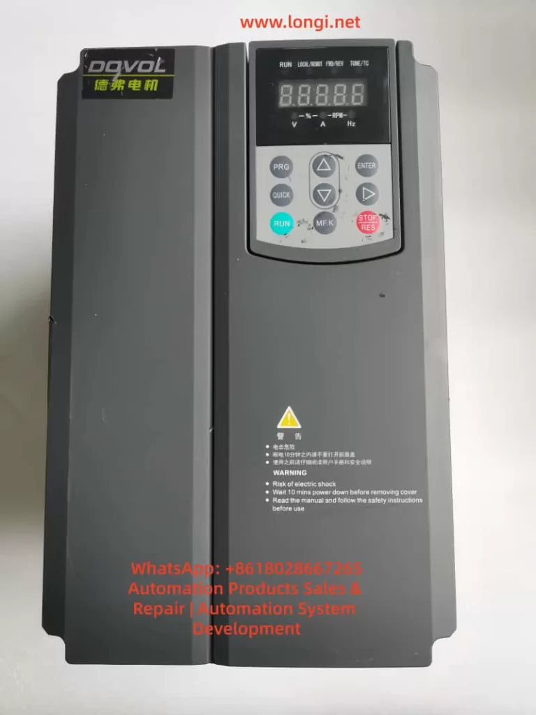
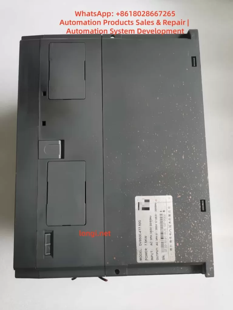
The DOVOL DV950E series permanent magnet synchronous frequency converter is a general-purpose, high-performance current vector frequency converter. It is mainly used to control and adjust the speed and torque of three-phase AC synchronous motors. This guide provides detailed information on the converter’s functional features, operation methods, parameter settings, and troubleshooting, helping users quickly master the skills of using the equipment.
II. Basic Functions and Wiring
Product Main Features
Control Modes: Supports sensorless vector control (SVC), sensor-based vector control (FVC), and V/F control.
Frequency Range: 0 – 500Hz.
Overload Capacity: 150% of the rated current for 60 seconds, 180% of the rated current for 3 seconds.
Speed Regulation Range: 1:50 in SVC mode, 1:1000 in FVC mode.
Built-in PID Regulator: Supports process closed-loop control.
Multiple Communication Protocols Supported: Modbus, ProfiBus-DP, CANlink, CANopen.
Electrical Installation Precautions
Main Circuit Wiring: Correctly distinguish between input terminals (R, S, T) and output terminals (U, V, W).
Braking Resistor: Do not connect the braking resistor directly between the DC bus (+) and (-) terminals.
Motor Cable Length: When the motor cable length exceeds 100m, install an AC output reactor.
Grounding: Ensure reliable grounding with a grounding wire resistance of less than 10Ω.
Power Supply Voltage: Before powering on, ensure that the power supply voltage matches the rated voltage of the frequency converter.
III. Operation Panel Usage
Panel Layout and Indicators
RUN: Running status indicator (lights up when in operation).
LOCAL/REMOT: Control mode indicator (off – panel control; on – terminal control; flashing – communication control).
FWD/REV: Forward/reverse rotation indicator (lights up for reverse rotation).
TUNE/TC: Tuning/torque control/fault indicator.
Five-digit LED Digital Display Area.
Function Keys: PRG (programming), ENTER (confirmation), ▲▼ (increase/decrease), ◄ (shift), etc.
Basic Operation Process
Enter the parameter setting mode by pressing the PRG key.
Select the function group using the ▲▼ keys.
Press ENTER to enter the specific parameter setting.
After modifying the parameter value, press ENTER to save it.
Press the PRG key to return to the previous menu.
IV. Core Function Implementation Methods
Motor Forward/Reverse Rotation Control
Method 1: Panel Control
Set P0-02 = 0 (panel command channel).
Set the running direction via P0-09 (0 – same direction; 1 – opposite direction).
Press the RUN key to start and the STOP key to stop.
Method 2: Terminal Control
Set P0-02 = 1 (terminal command channel).
Assign DI terminal functions: P4-00 = 1 (DI1 for forward rotation), P4-01 = 2 (DI2 for reverse rotation).
Control the on/off state of the DI terminals through external switches to achieve forward/reverse rotation.
Method 3: Communication Control
Set P0-02 = 2 (communication command channel).
Send forward/reverse rotation commands through communication (requires a communication card).
Note: To disable reverse rotation, set P8-13 = 1.
Frequency Regulation Methods
Digital Frequency Setting
Set P0-03 = 0 or 1 (digital setting).
Set the preset frequency via P0-08.
During operation, fine-tune the frequency using the panel ▲▼ keys or UP/DOWN terminals.
Analog Frequency Setting
Set P0-03 = 2 (AI1)/3 (AI2)/4 (AI3).
Configure the curve characteristics of the corresponding AI input (P4-13 – P4-27).
Adjust the frequency using an external potentiometer or PLC analog output.
Multi-speed Control
Set P0-03 = 6 (multi-speed instruction).
Assign DI terminals as multi-speed instructions (P4-00 – P4-09 = 12 – 15).
Set the frequency values for each speed segment in the PC group (PC-00 – PC-15).
PID Frequency Regulation
Set P0-03 = 8 (PID).
Configure the PID parameters in the PA group.
Automatically adjust the frequency based on the feedback signal.
Motor Parameter Tuning
No-load Tuning Steps
Ensure that the motor is mechanically decoupled from the load.
Correctly input the motor nameplate parameters (P1-01 – P1-05).
Set P1-37 = 12 (synchronous motor no-load tuning).
Press the RUN key to start tuning (approximately 2 minutes).
The parameters are automatically saved after tuning is completed.
Loaded Tuning Steps
Set P1-37 = 11 (synchronous motor loaded tuning).
Press the RUN key to start tuning.
The parameters are automatically saved after tuning is completed.
Note: Loaded tuning cannot obtain the back electromotive force coefficient, and the control accuracy is slightly lower than that of no-load tuning.
V. Advanced Function Configuration
Frequency Sweeping Function (Textile Applications)
Set PB-00 = 0 (relative to the center frequency) or 1 (relative to the maximum frequency).
Set PB-01 (frequency sweeping amplitude), PB-02 (jump amplitude).
Set PB-03 (frequency sweeping period), PB-04 (triangular wave rise time).
Control the frequency sweeping pause through the DI terminal (P4-xx = 24).
Fixed-length Control
Set DI5 function as length counting input (P4-04 = 27).
Set PB-07 (pulses per meter).
Set PB-05 (preset length).
Assign DO terminals as length arrival signals (P5-xx = 10).
Counting Function
Set DI terminals as counting input (P4-xx = 25) and reset (P4-xx = 26).
Set PB-08 (preset count value), PB-09 (specified count value).
Assign DO terminals as counting arrival signals (P5-xx = 8 or 9).
Timing Control
Set P8-42 = 1 (timing function enabled).
Set P8-44 (timing operation time) or select AI input via P8-43.
The equipment automatically stops after reaching the preset time.
VI. Fault Diagnosis and Handling
Common Fault Codes and Handling
Fault Code
Fault Type
Possible Causes
Handling Methods
Err02
Acceleration Overcurrent
Short acceleration time/heavy load
Extend the acceleration time P0-17/check the mechanical load
Err03
Deceleration Overcurrent
Short deceleration time
Extend the deceleration time P0-18
Err04
Constant-speed Overcurrent
Load突变 (Load mutation)/motor short circuit
Check the motor insulation/adjust the torque limit P2-10
Err09
Undervoltage
Low input voltage/power outage
Check the power supply voltage/set P9-59 for instantaneous power failure without stop
Err11
Motor Overload
Heavy load/undersized motor
Reduce the load/check the rated current setting P1-03
Err14
Module Overheating
High ambient temperature/poor heat dissipation
Improve the heat dissipation conditions/reduce the carrier frequency P0-15
Err20
Encoder Fault
Signal interference/wiring error
Check the encoder wiring/set P2-32 = 0 to disable Z correction
Fault Reset Methods
Panel Reset: Press the STOP/RES key in the fault state.
Terminal Reset: Set the DI terminal function to 9 (fault reset).
Communication Reset: Send a reset command through communication.
Fault Record Inquiry
Recent Fault: Check P9-16 – P9-22.
Second Fault: Check P9-27 – P9-34.
First Fault: Check P9-37 – P9-44.
VII. Maintenance and Upkeep
Daily Inspection
Check if the cooling fan is operating normally.
Check for loose wiring terminals.
Check if the enclosure temperature is abnormal.
Regularly remove dust from the radiator.
Regular Maintenance
Check the appearance of electrolytic capacitors every six months.
Check the insulation resistance annually (measure after powering off).
Replace the cooling fan every 2 years (depending on the operating environment).
Parameter Backup
Set PP-01 = 4 (backup user parameters).
To restore, set PP-01 = 501.
Restore to factory settings: PP-01 = 1.
VIII. Safety Precautions
Do not open the cover when powered on. After powering off, wait for 10 minutes before performing wiring operations.
Do not connect the braking resistor directly to the DC bus.
Perform an insulation check on the motor before the first use (≥5MΩ).
Derate the equipment when the altitude exceeds 1000m (derate by 1% for every 100m).
Derate the equipment when the ambient temperature exceeds 40℃ (derate by 1.5% for every 1℃).
Do not install capacitors or surge suppressors on the output side of the frequency converter.
This guide provides a detailed introduction to the various function implementation methods of the DV950E frequency converter. When using it in practice, please select the appropriate configuration method according to the specific application scenario. For complex application scenarios, it is recommended to contact the manufacturer’s technical support for more professional guidance.
Frequency range limitation: F0-10 = 50.00Hz, F0-12 = 50.00Hz, F0-14 = 0.00Hz.
III. Fault Diagnosis and Handling
3.1 Common Fault Codes and Solutions
Fault Code
Fault Type
Possible Causes
Solutions
ERR02
Acceleration Overcurrent
Load mutation, short acceleration time
Check the load, increase the acceleration time F0-17
ERR03
Deceleration Overcurrent
Short deceleration time, large load inertia
Increase the deceleration time F0-18, install a braking resistor
…
…
…
…
ERR20
Encoder Fault
PG card fault, wiring error
Check the encoder wiring, set the F1-36 detection time
3.2 Fault Information Query and Reset
Fault History Query:
F9-14 to F9-16: Record the types of the last three faults.
F9-17 to F9-46: Record the operating status parameters at the time of the fault.
Fault Reset Methods:
Panel reset: Press the STOP/RES key.
Terminal reset: Set the DI terminal to 9.
Communication reset: Send a reset command through Modbus communication.
3.3 Fault Protection Action Settings
Fault Action Selection 1 (F9-47):
Units digit: Motor overload action.
Tens digit: Input phase loss action.
Fault Action Selection 2 (F9-48):
Units digit: Encoder fault action.
Tens digit: Parameter read/write abnormal action.
Fault Action Selection 3 (F9-49):
Units digit: Custom fault 1 action.
Tens digit: Custom fault 2 action.
IV. Advanced Functions and Application Examples
4.1 Multi-Motor Control Function
Motor Parameter Group Selection:
Select the current motor parameter group using F0-24.
Motor Parameter Settings:
First group: F1 group (motor parameters), F2 group (vector parameters).
Second group: A2 group (motor parameters), A5 group (vector parameters).
Switching Notes:
Switching must be performed in the stop state.
After switching, check the motor rotation direction.
4.2 PID Control Function Application
Basic Parameter Settings:
FA-00: PID setpoint source selection.
FA-02: PID feedback source selection.
PID Parameter Settings:
FA-05: Proportional gain Kp1.
FA-06: Integral time Ti1.
FA-07: Differential time Td1.
4.3 Communication Function Configuration
Basic Parameter Settings:
Fd-00: Baud rate setting.
Fd-01: Data format.
Fd-02: Local address.
Communication Control:
Run command: Communication address 0x1001.
Frequency setpoint: Communication address 0x1000.
V. Maintenance and Upkeep
5.1 Daily Maintenance Points
Regular Inspection Items:
Check the operation of the cooling fan.
Remove dust from the radiator.
Check the wiring terminals.
Check the electrolytic capacitors.
Maintenance Cycle Recommendations:
Daily: Check the operating status.
Monthly: Clean the radiator.
Annually: Conduct a comprehensive inspection.
5.2 Long-Term Storage Notes
Storage Environment Requirements:
Temperature: -20°C to +60°C.
Humidity: ≤95%RH (no condensation).
Inspection Before Reuse:
Measure the insulation resistance of the main circuit.
Check the control board.
5.3 Lifespan Prediction and Replacement
Lifespan Reference for Wear Parts:
Electrolytic capacitors: Approximately 8-10 years.
Cooling fans: Approximately 30,000-50,000 hours.
Replacement Notes:
Cut off the power supply and wait for 10 minutes before operation.
After replacement, check the parameter settings.
Conclusion
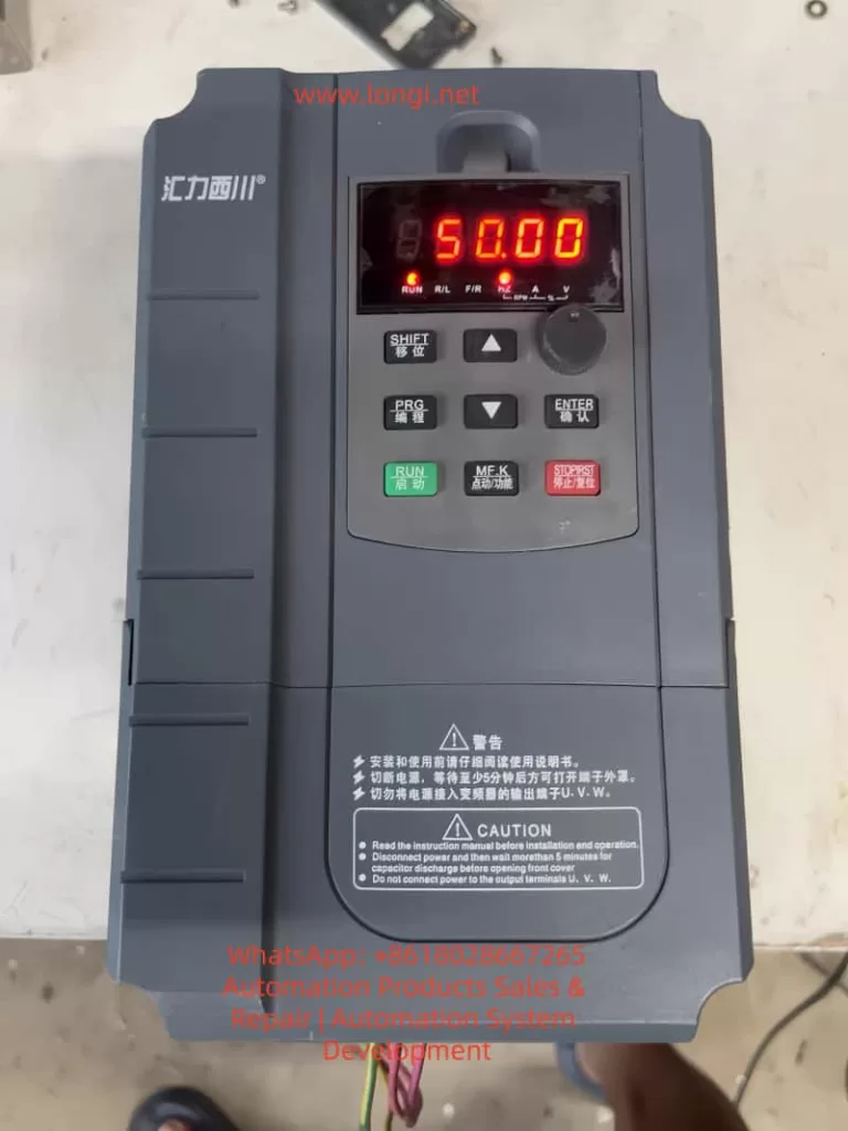
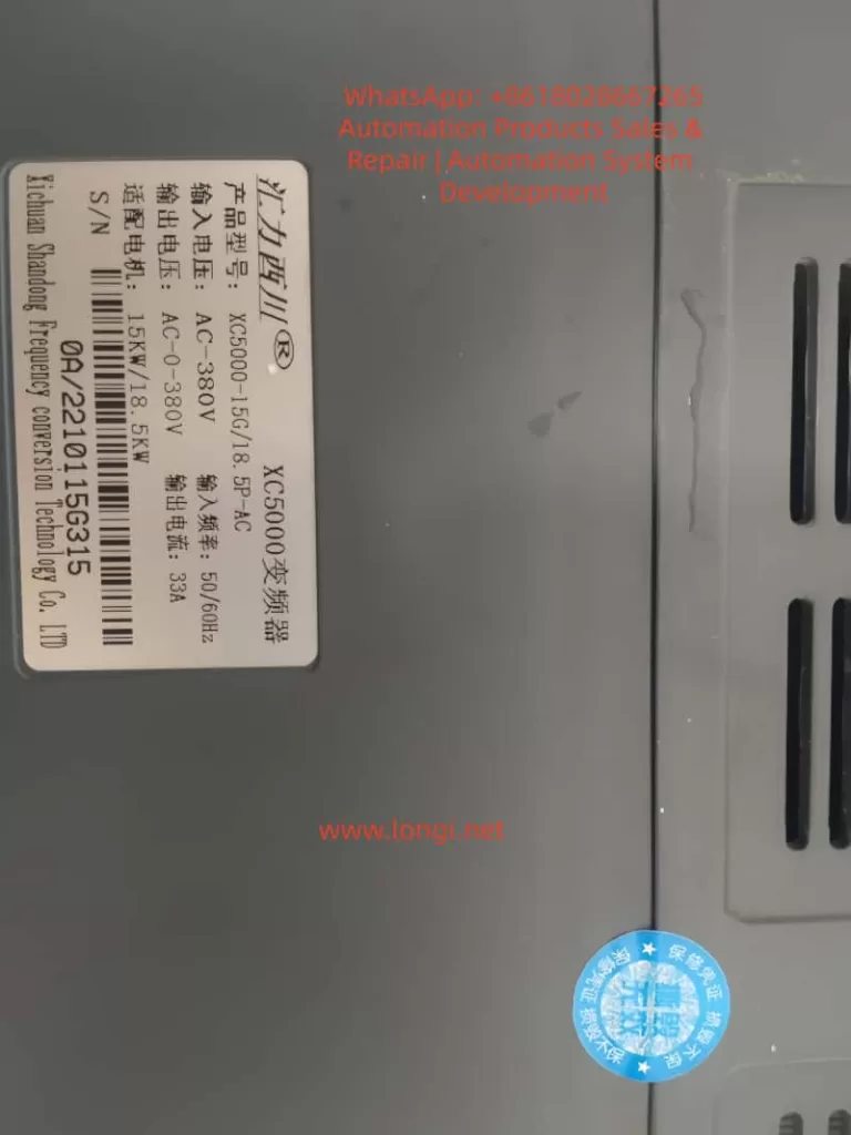
The XC-5000 series frequency converters are powerful and have superior performance. Through this guide, users can comprehensively master core skills such as operation panel usage, parameter settings, external control, and fault diagnosis. Correct installation, parameter settings, and maintenance are key to ensuring the long-term stable operation of the frequency converters. It is recommended that users refer to this guide and make appropriate adjustments according to specific working conditions to fully leverage the performance advantages of the XC-5000 frequency converters.
May falsely alarm on large-capacity inverters during power-on; temporarily disable detection if necessary
INF6 (Identification Error):
Check option module installation
Refer to [Identification Fault] inf6 code for specific analysis (0x01 = module no response, 0x02 = receive timeout, etc.)
3.2 Warning Message Handling
Typical Warnings:
FFdA (Fan Feedback Warning):
Abnormal fan speed
Check fan status and replace if necessary
FCtA (Fan Counter Warning):
Fan operating time exceeds 45,000 hours
Reset counter through [Time Counter Reset] rPr
DCRW (DC Bus Ripple Alarm):
Excessive DC bus voltage fluctuation
Check grid quality; add DC choke if necessary
3.3 Fault Troubleshooting Process
Viewing History Records:
Enter the [Diagnostics] dIA – [Error History Record] pFH menu
Analyze the last 15 fault records
Status Check:
Check [Inverter Status] HMIS
View secondary status in [Other Status] SSt
Reset Operation:
Press the STOP/RESET button after clearing faults
For stubborn faults, configure a dedicated reset input through [Fault Reset Allocation] rSF
IV. Advanced Functions and Application Tips
4.1 Motor Parameter Optimization
Self-Tuning Execution:
Enter the [Simple Start] SYS – [Self-Tuning] tUn menu
Select [Rotating Tuning] rot (requires load disconnection) or [Standard] std
Verify [Self-Tuning Status] tUS as [dOnE] after tuning
Advanced Motor Control:
[Advanced Motor Control] AEMC improves dynamic performance
Requires re-optimization of [Speed Loop Optimization] MCL parameters after enabling
4.2 Application Macro Configuration
Selecting Application Types:
Enter the [Complete Setup] CSt – [Macro Configuration] MCr menu
Choose from preset configurations such as [General Pump Control], [Hoisting and Lifting], [Conveyor Belt], etc.
Parameter Group Switching:
Configure the [Parameter Switching] MLP function
Switch between different parameter groups via digital inputs or communication
4.3 Communication Function Configuration
Fieldbus Integration:
Supports multiple protocols such as Modbus, CANopen, and PROFINET
Configure network parameters through the [Communication] COM menu
Web Server Functionality:
Enable [Web Server] WbS for remote monitoring
Set a complex password (at least 8 characters, including uppercase and lowercase letters and special characters)
V. Maintenance and Safety
5.1 Regular Maintenance Items
Inspection Items:
[Motor Operating Time] rtHH
[Fan Operating Time] FPbt
[Number of Starts] nSM
Maintenance Reset:
Clear timers through [Time Counter Reset] rPr
5.2 Safety Precautions
Electrical Safety:
Wait 15 minutes after power-off to allow capacitor discharge
Use voltage detection to confirm power-off
Operational Safety:
Install inverters outside hazardous areas
Ensure emergency stop circuits are independent of inverter control
Network Security:
Disable remote access functions when not in use
Regularly back up parameter configurations
This guide is compiled based on the ATV900 Series Universal Programming Manual (NHA80762). For practical applications, verify parameter availability in conjunction with specific models and firmware versions. For complex application scenarios, it is recommended to use Schneider Electric’s SoMove configuration software for detailed debugging.
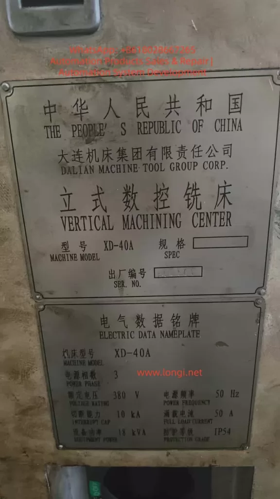
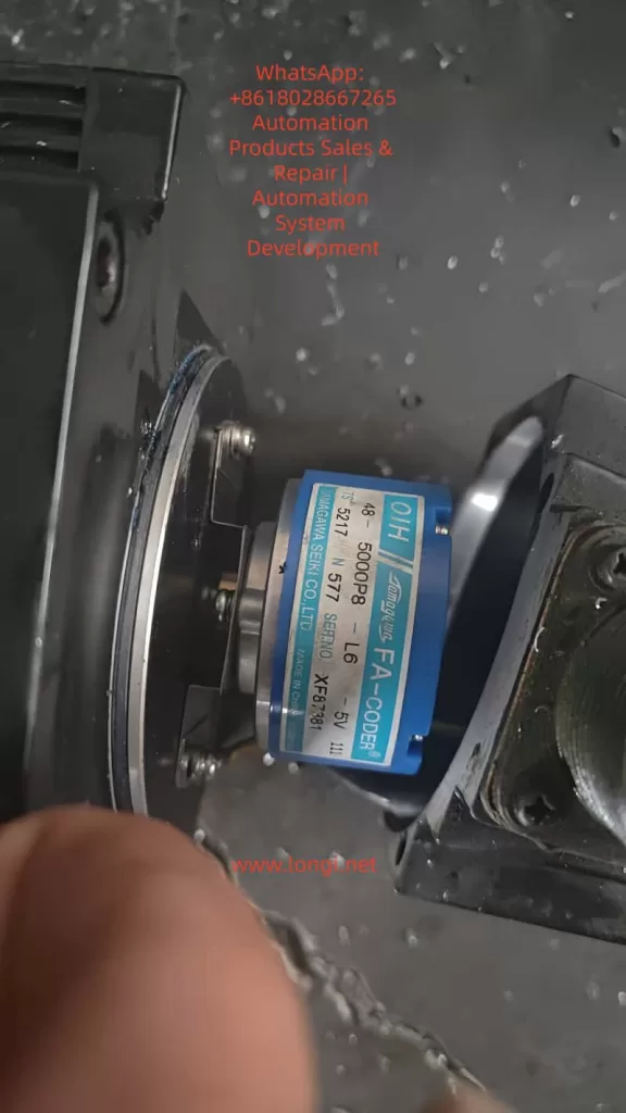
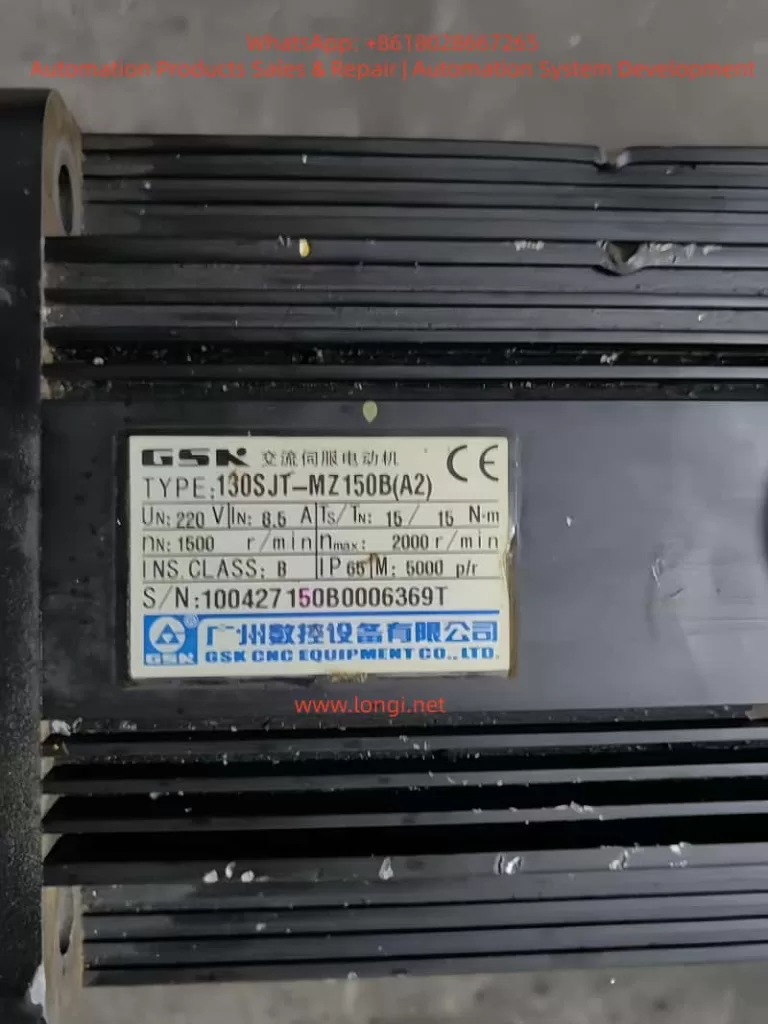
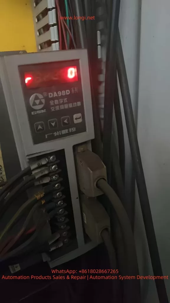
In CNC machining center maintenance and commissioning, the calibration of the Z-axis reference point and tool change point is critical for ensuring the machine’s precision and stability. This article takes the XD-40A vertical machining center manufactured by Dalian Machine Tool Group as an example. The machine is equipped with a GSK983Ma-H CNC system, DA98D servo drive, and a Sanyo OIH 5000P/R incremental encoder. The machine adopts an umbrella-type tool magazine, where the Z-axis must accurately position at the second reference point during tool change.
During routine maintenance, the Z-axis servo motor was replaced. After replacement, the machine could start and home normally, but an abnormality appeared during tool change (M06): The Z-axis stopped about 3 mm higher than before, causing the spindle taper to fail to engage the tool holder. The operator had to manually lower the Z-axis by 3 mm to complete the tool change.
Although this deviation did not trigger any alarms, it seriously affected the reliability of automatic tool change and could lead to tool gripper misalignment, incomplete release, or even tool crashes.
II. System Structure and Signal Relationship Analysis
To solve the issue, it is essential to understand how the GSK983Ma-H system defines the Z-axis “reference point (home position).” The Z-axis homing position is determined by two signals:
Proximity switch signal (HOME/ORG) – used for coarse positioning;
Encoder Z-phase signal (Z-phase) – used for fine positioning.
When the machine executes the “Home” (G28 Z0) command after power-up, the sequence is as follows:
The Z-axis moves in the specified direction until it detects the proximity switch signal.
The system records the pulse position at this point.
After the proximity signal is released, the axis continues moving.
When the next Z-phase pulse is detected, the system defines that position as the machine reference point (zero point).
Based on parameter 0161, the system then calculates the second reference point (e.g., tool change point).
Thus, the Z-axis zero position is not determined by the limit switch alone, but by the phase relationship between the proximity signal and the encoder Z-phase pulse.
III. Root Cause Analysis After Motor Replacement
In this case, the proximity switch, lead screw, and limit mechanism remained unchanged, yet a 3 mm tool change deviation occurred after replacing the motor. The underlying causes are as follows:
1. Encoder Z-phase Signal Phase Difference
Even among identical motor models, the internal encoder Z-phase position relative to the rotor magnetic pole can vary slightly due to manufacturing tolerances. When the system executes “find proximity then find Z-phase,” a phase delay or advance changes the zero-point position.
For a 5000-line encoder: [ 5\text{ mm / rev} \Rightarrow 1 \text{ Z pulse = 5 mm} ] If the Z-phase triggers 0.6 turns later, the system’s reference point shifts upward by approximately 3 mm.
2. Coupling Installation Angle Deviation
If the motor–lead screw coupling is reassembled with a slight angular misalignment or reversed orientation, the timing between the proximity and Z-phase signals changes, causing a fixed offset.
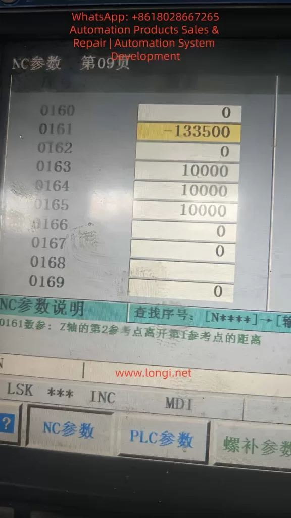
3. Second Reference Point Parameter Not Recalibrated
Parameter 0161 in the GSK system defines the distance between the first and second reference points. If the old value is retained after encoder replacement, the stored Z-phase relationship becomes invalid, resulting in a tool change height deviation.
4. Servo Phase Angle or Polarity Mismatch
If the servo drive’s electrical phase offset (in DA98D) is not re-calibrated, it can cause inconsistent homing. However, such errors typically lead to random deviations, not a consistent 3 mm offset.
IV. Parameter Framework and Signal Interaction
The GSK983Ma-H system controls Z-axis referencing using several key parameters:
Parameter
Description
Function
0160
Home direction
Defines positive or negative direction of homing
0161
Distance from 1st to 2nd reference point
Defines tool change position
0162
Home offset
Compensates fine homing deviation (if available)
0163–0165
Homing speeds
Control homing speed at each stage
0171–0175
Home switch logic
Defines trigger mode and direction
Thus, the final tool change position can be expressed as: [ Z_{tool} = Z_{prox} + ΔZ_{Z-phase} + P_{0161} ] Any change in the above components—especially the Z-phase offset—will cause a physical shift in the tool change height.
V. Comparative Analysis of Available Solutions
When parameter modification (0161) is restricted by password protection, alternative methods must be considered. Below is a comparison of practical options used in the field.
Method
Principle
Application
Advantage
Risk
Modify 0161
Adjusts tool change offset
If password available
Accurate and safe
Requires password
Adjust proximity switch
Shifts home reference mechanically
No password
Simple and direct
Changes all Z references
Change servo electronic gear ratio
Alters pulses per unit
Mismatch in lead screw
Fixes scaling
Affects entire travel accuracy
Modify home offset (if available)
Software correction
Some versions only
No mechanical adjustment
Usually locked
Adjust motor phase
Alters encoder–rotor relationship
Encoder misalignment
Permanent correction
Complex, risky
Conclusion:
If password access is available, adjusting 0161 is best.
If not, physically adjusting the proximity switch by 3 mm is the most practical.
Avoid changing gear ratios unless lead screw or encoder specifications differ.
VI. Practical Solution Without Password Access
When the system password is unknown or locked, the following mechanical method effectively corrects the deviation.
1. Required Tools
Hex wrench, caliper or feeler gauge, insulation gloves, and a tool holder or alignment gauge.
2. Determine Adjustment Direction
If Z-axis stops too high → move the proximity switch upward.
If Z-axis stops too low → move the switch downward.
3. Adjustment Procedure
Power off the machine.
Loosen the Z-axis home switch screws.
Move the switch up by approximately 3 mm.
Tighten screws and power on.
Re-home the Z-axis and test tool change.
4. Verification
Execute:
G28 Z0
M06 T1
Check if the spindle taper aligns with the tool gripper. Fine-tune the switch by ±0.5 mm if needed.
5. Update Work Coordinate
Since the machine reference has shifted, redefine the Z=0 in G54 by touching off the workpiece again.
VII. DA98D Drive Parameter Verification
To ensure that the deviation is not caused by drive scaling, verify the following parameters in the DA98D servo drive:
Parameter
Function
Recommended
Description
P1.05
Electronic gear numerator
20000
Encoder output per rev
P1.06
Electronic gear denominator
1
1:1 transmission
P2.04
Home polarity
Depends on axis
Match direction
P4.01
Auto phase calibration
Execute after motor replacement
Syncs magnetic poles
Any incorrect electronic gear ratio can cause axis scaling errors and must be restored to 1:1.
VIII. Pulse Calculation for 3 mm Offset
Given:
Lead screw pitch = 5 mm
Encoder = 5000 PPR
Pulses per revolution = 5000 × 4 = 20000
Pulses per mm = 20000 ÷ 5 = 4000
Then: [ 3 \text{ mm} × 4000 = 12000 \text{ pulses} ] To compensate for a 3 mm height difference, parameter 0161 should change by ±12000 pulses. For example:
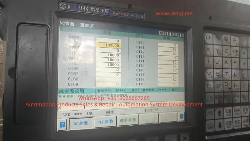
0161: -133500 → -145500
IX. Unlocking System Parameters
If full software correction is preferred, parameter protection can be disabled as follows:
Navigate to: SYSTEM → PARAM → NC PARAM
Press SET;
When prompted, enter one of the following passwords:
Password
Description
983
GSK default
889
Service engineer code
1111 / 0000
User level
1314 / 8888
OEM-defined
After successful entry, “Protection Released” appears at the bottom of the screen, allowing parameter editing.
If unavailable, restart and hold DELETE or ALT+M during boot to enter the maintenance menu and disable “Parameter Protection.”
X. Understanding the Z-Axis Homing Logic
The following illustrates the Z-axis homing process:
From that zero, parameter 0161 defines the tool change position.
If the Z-phase occurs later relative to the proximity switch, the zero point shifts upward, making the spindle stop higher during tool change. By moving the proximity switch 3 mm upward, the zero point effectively moves downward by 3 mm, correcting the deviation.
XI. Key Lessons and Maintenance Practices
Always re-calibrate reference points after replacing incremental encoders. Even a small Z-phase shift can cause millimeter-level errors.
Back up all NC parameters before maintenance. Parameter loss or mismatch is a frequent cause of deviation.
Prefer software compensation over mechanical adjustments. Mechanical adjustments are practical but less precise.
Do not change electronic gear ratios arbitrarily. They affect all axis scaling, not just tool change height.
Umbrella-type tool changers rely heavily on parameter 0161. Incorrect values lead to failed or dangerous tool changes.
After adjustment, verify through a full test:
Home the Z-axis;
Execute tool change;
Check gripper alignment;
Recalibrate work coordinate (G54).
XII. Conclusion
This study analyzed a real case of Z-axis tool change deviation on an XD-40A vertical machining center equipped with GSK983Ma-H control and DA98D servo drives. Through a detailed investigation of encoder Z-phase behavior, servo drive settings, and CNC reference logic, it was concluded that the 3 mm deviation was caused by a Z-phase timing difference, not mechanical misalignment.
When parameter modification is possible, adjusting parameter 0161 is the optimal solution. When access is restricted, mechanically adjusting the proximity switch by 3 mm effectively compensates for the offset. If hardware specifications differ, recalibration of the electronic gear ratio is necessary.
This case highlights that CNC positioning precision depends not only on mechanical accuracy but also on the synchronization between hardware signals and software logic. A deep understanding of the system’s internal mechanisms allows technicians to restore functionality efficiently, accurately, and safely.
I. Introduction: The Core of Modern Motion Control
In industrial automation, servo systems are the heart of precision control. From CNC machinery and robotics to packaging and inspection equipment, servos dictate accuracy, stability, and efficiency. Fuji Electric’s ALPHA5 series servo systems are widely known for their high response, precision, low noise, and reliability. However, commissioning and maintenance require a solid technical foundation. This article provides a complete, field-oriented explanation of the Fuji ALPHA5 series, covering wiring, parameters, software setup, diagnostic tools, and common repair practices.
II. System Overview and Working Principle
1. System Components
A standard ALPHA5 servo setup consists of:
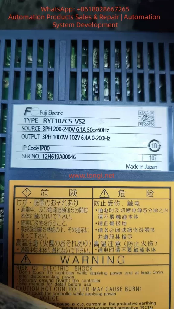
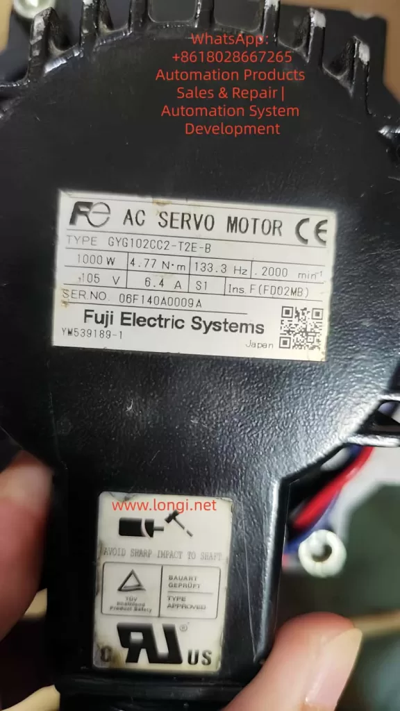
Servo amplifier (drive) – e.g., RYT102C5-VS2, performing power conversion and control.
AC servo motor – e.g., GYG102CC2-T2E-B, 1 kW, 17-bit absolute encoder.
Encoder cable (CN2) – provides position feedback.
I/O control cable (CN1) – handles enable, limit, reset, and I/O commands.
Communication ports (CN3A/CN3B) – for RS-485, Modbus, or Fuji serial protocol.
2. Operating Principle
The ALPHA5 employs advanced vector control integrating torque, speed, and position loops. Its Tamagawa TS5668N26 17-bit absolute encoder provides 131,072 counts per revolution. The amplifier calculates feedback errors in real time and adjusts three-phase PWM output for precise position and velocity control. When powered on, the drive handshakes with the encoder to identify the motor model and load proper parameters.
III. Installation and Wiring Guidelines
1. Power and Main Circuit
Input: 3-phase 200–240 V, 50/60 Hz
Output: 3-phase 0–200 Hz, rated 6.4 A
Always use shielded cables and ensure the chassis (PE) is solidly grounded.
2. Encoder Wiring (CN2)
Drive CN2
Motor Encoder
Signal
Description
1
H
P5
+5 V supply to encoder
2
G
M5
0 V (ground)
5
S
SIG+
Differential signal +
6
T
SIG–
Differential signal –
—
C/D
BAT+ / BAT–
Battery lines (optional)
Shell
J
FG
Shield/Frame ground
Notes:
BAT± are used only when absolute position retention is required; they can remain unconnected.
Reversed SIG+ / SIG– prevents motor identification (PA2_98 = 0).
3. Control I/O (CN1)
Typical CN1 pin functions:
Pin
Signal
Description
1
COMIN
Common input
2
CONT1
Configurable input
5
CONT4
Configurable input
7
+OT
Positive limit input
8
–OT
Negative limit input
10
EMG
Emergency stop input
18
TREF
Analog speed reference
21
CB
Brake control output
25
FZ
Zero-speed output
26
M5
Common ground
IV. Parameter Initialization and Basic Settings
1. Initialization Procedure
Enter the menu: MODE → SET → PA0_01 = 1.
After reset, display shows A000 (no position data).
When encoder handshake succeeds, PA2_98 automatically shows the motor type (e.g., 8 = GYG102CC2).
2. Key Parameters
Parameter
Name
Description
Typical Value
PA2_98
Motor model
Auto-detected, read-only
Auto (8 = GYG102CC2)
PA2_99
Encoder type
0 = incremental; 1 = 17-bit absolute; 2 = 20-bit
1
PA1_02
Control mode
0 = torque; 1 = speed; 2 = position
As required
PA1_50–PA1_59
Input terminal assignment
Defines external inputs (+OT, –OT, etc.)
Application-specific
PA3_26–PA3_30
CONT input logic
A/B logic (normally open/closed)
B for limit signals
V. Trial Operation and PC Loader Diagnostics
1. PC Loader for ALPHA5
Fuji’s PC Loader software provides graphical diagnostics and trial run capability. After connection:
S-ON lamp = servo enabled
+OT / –OT lamps = limit signals active
Real-time data for voltage, current, and speed appear on screen
2. Releasing Limit Lock (+OT / –OT)
If limit switches are unused:
Locate terminals assigned to function 21 (+OT) and 22 (–OT).
Change both to 0 = Unused.
Or physically short the limit input pins to COMIN.
Reboot the drive — limit indicators should go off and trial run becomes available.
VI. Common Faults and Solutions
Symptom
Cause
Remedy
Display shows A000
Default after initialization
Normal
Motor free, not locked
Encoder not recognized (PA2_98 = 0)
Check CN2 wiring, SIG± polarity
+OT/–OT active
Limit inputs asserted
Modify parameters or short terminals
ERR lamp flashing
Alarm detected
Read alarm code via PC Loader
Motor oscillates
Excessive gain or inertia mismatch
Adjust PA5_01/PA5_02 gains
Reverse direction
Phase or encoder polarity mismatch
Swap U-V-W or change PA1_04
Motor overheats
Overload or cooling blocked
Clean fan path, verify DC bus voltage (~320 V)
VII. Encoder Identification and Repair
1. Encoder Type
The motor uses Tamagawa TS5668N26, containing chip AU5798N2, a 17-bit absolute encoder communicating via differential serial lines (SIG±). The drive automatically reads motor ID at power-up.
2. Communication Failure Symptoms
No alarm but PA2_98 remains 0
Motor not energized (shaft free) Causes: Reversed SIG polarity or mis-crimped connector. Fix: Correct wire mapping and reboot — drive will identify the motor.
3. Encoder Service Notes
Supply 5 V DC, current ≈ 80 mA
Check differential output symmetry using an oscilloscope
Always connect shield (FG) properly
Never plug/unplug encoder cable under power — encoder IC damage is likely.
VIII. Input/Output Logic Details
1. “A” / “B” Logic
A-logic = active high (normally open)
B-logic = active low (normally closed) Safety signals like +OT, –OT, and EMG use B-logic by default.
2. Example
With a normally-closed limit switch on +OT:
Normal = closed → valid low → motion enabled
At limit = open → drive detects +OT active → output inhibited
If limit switches are not installed:
Set +OT/–OT functions to 0 (Unused), or
Short input pins to COMIN to simulate safe state.
IX. Field Repair and Troubleshooting Cases
Case 1: Encoder Not Detected
Symptom: PA2_98 = 0, motor free, display A000 Checks:
CN2 open-circuit → repair wiring
SIG+ / SIG– swapped → correct connections
Reboot → PA2_98 = 8 (GYG102CC2) → OK
Case 2: Limit Active, Servo Locked
Symptom: +OT/–OT lit simultaneously Cause: Limit inputs left open (B-logic) Fix: Set PA3_26/27 from 7/8 to 0 (Unused)
Case 3: Motor Vibration
Cause: Gain too high or inertia mismatch Fix: Tune speed loop gain (PA5_01) and position gain (PA5_02); enable Auto Tuning
Case 4: Motor Overheating
Cause: Continuous overload or blocked airflow Fix: Clean fan path, reduce load, verify bus voltage ≈ 320 V
X. Maintenance and Best Practices
Do not hot-plug the encoder cable. The encoder line carries 5 V DC; hot-plugging can destroy the AU5798N2 chip.
Grounding and shielding. The encoder shield (FG) must be bonded to the drive frame to prevent noise errors.
Cooling inspection. Clean the heat sink and check fan operation regularly.
Parameter backup. Use PC Loader to export all parameters before replacement or repair.
Battery maintenance (if absolute mode used). Replace the 3.6 V lithium cell periodically to retain multi-turn position.
XI. Conclusion
The Fuji ALPHA5 servo system combines precision, speed, and robustness for demanding automation applications. By mastering proper wiring, parameter configuration, and diagnostic tools, engineers can efficiently commission new systems and resolve faults in the field. Understanding the logical relationship between encoder feedback, input signal mapping, and safety interlocks ensures both high performance and reliability. With preventive maintenance and data backup practices, ALPHA5 drives can operate reliably for many years in production environments.
Technical Summary: This document is based on extensive field experience with Fuji ALPHA5 models such as RYT102C5-VS2 and GYG102CC2 servo motors. It provides a comprehensive reference for automation engineers, maintenance technicians, and system integrators seeking to maximize the stability and serviceability of Fuji servo systems.
Preamble: Getting to Know the Weite TW-ZX Series Frequency Inverter
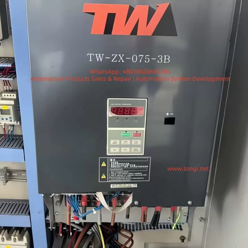
The Weite TW-ZX series frequency inverter is a high-performance drive control device specifically designed for lifting equipment. It is particularly suitable for precise control of heavy-duty machinery such as construction elevators and tower cranes. As a leading electrical transmission solution in the industry, this series of frequency inverters integrates advanced motor control algorithms and a rich set of functional configurations, enabling it to meet the stringent requirements of various lifting application scenarios.
This technical guide will comprehensively analyze the functional features, installation specifications, parameter settings, and maintenance essentials of the Weite TW-ZX frequency inverter, aiming to provide users with a systematic operational reference. By thoroughly understanding the content of this manual, users can fully leverage the performance advantages of the equipment, ensuring the safe, stable, and efficient operation of lifting equipment.
The TW-ZX series frequency inverter adopts optimized control algorithms specifically tailored for lifting applications, featuring core characteristics such as low-frequency high-torque output, intelligent braking control, and wide voltage adaptability. It is renowned in the industry for its high reliability and exceptional control precision. Below, we will commence with an overview of the product’s features and gradually unfold a complete application guide for this professional device.
I. Core Product Features and Technical Advantages
1.1 Professional Lifting Control Functions
The Weite TW-ZX frequency inverter is specifically designed for the lifting industry, incorporating a range of highly targeted professional functions:
Low-Frequency High-Torque Output: At 0.5Hz, it can provide 150% of the rated torque, ensuring stability during heavy-load startups and low-speed operations. This feature is particularly suitable for tower crane hoisting and elevator applications, addressing the industry challenge of insufficient torque in traditional frequency inverters at low frequencies.
Intelligent Brake Control Logic: It incorporates optimized braking timing control to precisely coordinate the actions of mechanical brakes and motors. Parameters Fb-00 to Fb-11 allow for flexible adjustment of brake release/closure frequencies and delay times, effectively preventing hook slippage and significantly enhancing operational safety.
Dynamic Current Limiting Technology: Advanced current control algorithms automatically adjust output during severe load fluctuations, preventing frequent overcurrent trips. Users can configure current stall protection characteristics via parameter FC-07 to balance system response speed and stability.
Wide Voltage Adaptability: The input voltage range extends up to 380V±20%, with automatic voltage regulation (AVR) functionality. It maintains sufficient torque output even when grid voltage drops, making it particularly suitable for construction sites with unstable grid conditions.
1.2 Hardware Design Characteristics
The TW-ZX series reflects the unique needs of lifting equipment in its hardware architecture:
Enhanced Cooling Design: The entire series adopts a forced air cooling structure with real-time protection against overheating of the散热器 (radiator) (OH fault), ensuring reliable operation in high-temperature environments. Larger power models (above 90kW) utilize an up-draft and down-draft air duct design to optimize cooling efficiency.
Modular Power Units: The power modules employ industrial-grade IGBT devices with an overload capacity of 150% rated current for 1 minute and 180% rated current for 10 seconds, fully meeting the short-term overload requirements of lifting equipment.
Rich Interface Configuration: It provides 7 multifunctional digital input terminals (X1-X7), 2 analog inputs (VS/VF for voltage signals, IS/IF for current signals), 2 open-collector outputs (Y1/Y2), and 1 relay output (R1), catering to complex control needs.
Built-in Brake Units (Select Models): Models below 18.5kW come standard with built-in brake units, allowing direct connection to brake resistors. Larger power models require external dedicated brake units, with the BR100 series recommended as a complementary product.
1.3 Control Performance Advantages
Compared to general-purpose frequency inverters, the TW-ZX series has undergone in-depth optimization in its control algorithms:
Optimized S-Curve Acceleration/Deceleration: Parameter FC-00 enables the S-curve acceleration/deceleration mode, with FC-01/02 setting the S-curve proportions for the acceleration and deceleration phases, respectively, effectively reducing mechanical shock and enhancing operational smoothness.
Multi-Speed Precise Control: It supports up to 16 preset speed stages (F3-00 to F3-14), allowing rapid switching through terminal combinations to meet the speed requirements of lifting equipment under various operating conditions. Each speed stage can independently set acceleration and deceleration times (F3-15 to F3-20).
Motor Parameter Self-Learning: It offers both stationary and rotational self-identification modes (F1-15) to automatically measure motor electrical parameters, significantly improving vector control accuracy. For applications where the load cannot be decoupled, the stationary identification mode provides a safe and reliable option.
Table: Typical Models and Specifications of the TW-ZX Series Frequency Inverter
Model
Rated Power (kW)
Rated Current (A)
Brake Unit
Dimensions (mm)
TW-ZX-011-3
11
26
Built-in
270×200×470
TW-ZX-022-3
22
48
Built-in
386×300×753
TW-ZX-045-3
45
90
Built-in
497×397×1107
TW-ZX-110-3
110
220
External
855×825×793
II. Equipment Installation and Electrical Wiring Specifications
2.1 Mechanical Installation Requirements
Proper installation is fundamental to ensuring the long-term reliable operation of the frequency inverter. The TW-ZX series requires particular attention to the following points during installation:
Installation Orientation: It must be installed vertically to ensure unobstructed airflow through the cooling ducts. Sufficient space (recommended ≥100mm) should be left on all sides to prevent heat accumulation. When multiple frequency inverters are installed side by side in a control cabinet, the ambient temperature should not exceed 40℃.
Environmental Conditions: The operating environment should have a temperature range of -10℃ to +40℃ and a humidity range of 20% to 90%RH (non-condensing). It should be avoided in locations with conductive dust, corrosive gases, or oil mist, and kept away from vibration sources and electromagnetic interference sources.
Vibration Protection: The installation base should be sturdy and vibration-free, with a maximum allowable vibration of 0.5g. For vehicle-mounted or mobile equipment applications, shock absorbers are recommended to prevent internal components from loosening due to prolonged vibration.
Protection Level: Standard models have a protection level of IP20 and are not suitable for direct exposure to outdoor or humid environments. For special environments, customized protective enclosures or models with higher protection levels should be selected.
2.2 Main Circuit Wiring Specifications
The main circuit wiring directly affects system safety and EMC performance, and must strictly adhere to the following specifications:
Power Input Terminals (R/S/T):
A suitable circuit breaker (MCCB) must be installed, with a rated current of 1.5 to 2 times the rated value of the frequency inverter.
The power cable cross-sectional area should be selected according to Table 3-3, ensuring a voltage drop not exceeding 5V.
An AC reactor (optional) can be installed on the input side to suppress grid surges and harmonics.
Motor Output Terminals (U/V/W):
Motor cables should be shielded cables or laid through metal conduits to reduce electromagnetic radiation.
It is absolutely prohibited to install power factor correction capacitors or LC/RC filters on the output side.
When the motor wiring length exceeds 50 meters, the carrier frequency should be reduced or an output reactor should be installed.
Brake Resistor Connection:
For models with built-in brake units, connect to the PB terminals. For models with external brake units, connect to the P/N terminals.
The resistance value and power rating must be strictly selected according to Table 11-1 to prevent overload damage to the brake unit.
Brake resistor wiring must use high-temperature-resistant cables and be kept away from flammable materials.
Grounding Requirements:
The protective grounding terminal must be reliably grounded (Class III grounding, grounding resistance <10Ω).
The grounding wire cross-sectional area should be no less than half of the power cable cross-sectional area, with a minimum of 16mm².
When grounding multiple frequency inverters, avoid forming grounding loops and adopt a star grounding configuration.
2.3 Control Circuit Wiring Essentials
The control circuit serves as the bridge for interaction between the frequency inverter and external devices, and special attention should be paid to the following points during wiring:
Analog Signal Processing:
Speed reference signals (VS/VF) should use twisted-pair shielded cables, with the shield grounded at one end.
Signal lines should be separated from power lines by a distance of no less than 30cm and arranged perpendicularly when crossing.
Jumpers JP1/JP2 can select the analog output M0/M1 to operate in voltage (0-10V) or current (0-20mA) mode.
Digital Terminal Configuration:
By default, X1 is set for operation, X2 for forward/reverse rotation, and X3-X7 are programmable for functions such as multi-speed control (F2-00 to F2-06).
The PLC common terminal can be connected to either 24V or COM, supporting both NPN and PNP wiring modes.
The relay output R1 (EA-EB-EC) can directly drive contactor coils, with a contact rating of 250VAC/3A.
RS485 Communication:
Use shielded twisted-pair cables to connect the A+/A- terminals, with proper termination resistor matching.
Communication parameters are set via F1-16 to F1-19, supporting the Modbus RTU protocol.
It is recommended to set the baud rate not exceeding 19200bps and reduce the rate for long-distance communication.
Figure: Standard Wiring Diagram for the TW-ZX Frequency Inverter [Insert wiring diagrams similar to Figures 12-1 to 12-4 here, showcasing typical application wiring for elevators, tower crane hoisting, etc.]
III. Parameter Settings and Functional Configuration
3.1 Basic Parameter Setting Procedure
After powering on the TW-ZX frequency inverter, follow the procedure below for basic settings:
Restore Factory Settings:
Set F0-28=1 to restore the factory settings corresponding to the application macro.
Select F4-28=9 for elevator applications and F4-28=6 for tower crane hoisting applications.
After resetting, check F0-27=1 to ensure all parameter groups are displayed.
Motor Parameter Input:
Accurately input the motor nameplate data (F1-00 to F1-07).
For elevators with dual motors in parallel, set the power and current to the sum of the two motors.
The motor winding connection method (F1-06) must match the actual configuration (Y/△).
Motor Parameter Self-Learning:
Perform rotational self-identification (F1-15=2) after decoupling the load.
If the load cannot be decoupled, select stationary self-identification (F1-15=1).
Do not operate the frequency inverter during the identification process. Parameters are automatically stored upon completion.
Speed Control Parameters:
Set the maximum frequency F0-16 (usually 50Hz) and the upper limit frequency F0-17.
Adjust the acceleration time F0-09 and deceleration time F0-10, extending them appropriately for heavy loads.
The carrier frequency F0-14 is generally set to 1-4kHz, and can be increased if noise is significant.
Terminal Function Allocation:
Configure X3-X7 according to application requirements for functions such as multi-speed control and fault reset.
Set the output functions for Y1/Y2/R1, such as fault signals and brake control.
3.2 Configuration of Lifting-Specific Functions
The TW-ZX series requires special configuration for the unique functions tailored to lifting applications:
Brake Control Timing:
Set the ascending brake release frequency Fb-00 (usually 3Hz) and the descending release frequency Fb-01.
Configure the pre-release delay Fb-02 (approximately 0.3s) and the post-release delay Fb-03.
Set the brake closure frequencies Fb-04/Fb-11 and the corresponding delays Fb-05/Fb-06.
Zero-Crossing Acceleration Function:
Enable Fb-09 to set the zero-crossing acceleration/deceleration time (approximately 2s).
Adjust Fb-10 to set the frequency point for acceleration/deceleration changes (usually 2.5Hz).
Combine with S-curve parameters FC-01/02 to achieve smooth transitions.
Brake Inspection Function:
Set the inspection torque Fd-09 (150% of rated) and time Fd-10 (4s).
Define the inspection interval Fd-16 (e.g., 80 hours).
Set the Y2 terminal to provide a brake inspection reminder (F2-13=27).
Industry-Specific Protections:
Disable current limiting FC-07=0 and overvoltage stall FC-19=0010.
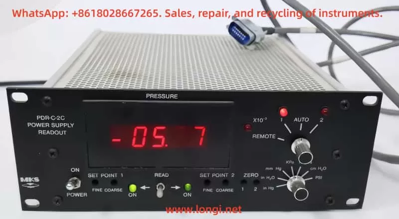
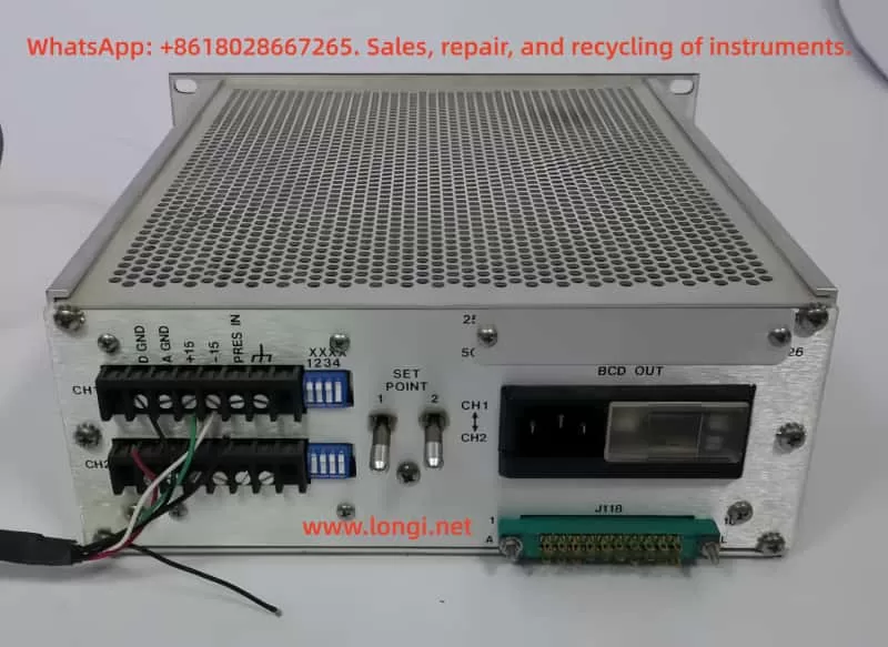
The MKS PDR-C-2C is a professional-grade power supply and digital readout system designed for industrial pressure monitoring and control applications. As a mature product from MKS Instruments, the PDR-C-2C features a standard half-rack mount design, integrating high-precision power supply and dual-channel pressure signal processing capabilities.
Core Features:
Dual-Channel Pressure Monitoring: Connects to two independent pressure sensors for wide-range pressure monitoring.
High-Precision Digital Display: 4½-digit LED panel meter provides readings accurate to 0.01%.
Programmable Setpoint Control: Equipped with two independent setpoint relays for customizable trigger thresholds.
Stable Power Output: Provides ±15VDC/600mA dual outputs to meet most pressure sensor requirements.
Auto Channel Switching: Intelligently monitors dual-channel pressure values and automatically switches to display the sensor data with the optimal range.
Compared to the single-channel version PDR-C-1C, the PDR-C-2C adds dual-sensor interfaces and intelligent channel management, making it ideal for applications requiring wide-range pressure monitoring. The system’s modular design ensures easy maintenance, with all key parameters adjustable directly from the front panel without the need for specialized tools.
Safety Operating Procedures
As an electronic measurement device, the MKS PDR-C-2C must be used in strict compliance with safety regulations to prevent personal injury and equipment damage.
Electrical Safety Warnings:
Grounding Requirements: The device must be properly grounded through the grounding conductor of the power cord. Loss of protective grounding connection may result in all accessible conductive parts (including seemingly insulated knobs and controls) becoming live, posing an electric shock risk.
Power Supply Considerations:
Use only a power cord that meets specifications (conductor cross-sectional area ≥ 0.75mm²).
Use only the specified fuse type (1ASB for 120VAC, ½ASB for 240VAC).
Power voltage range: 117/234V ± 15%, 50-60Hz.
High Voltage Warning: High voltages are present in cables and sensors when the controller is powered on. Non-professionals are prohibited from opening the device casing.
Operating Environment Requirements:
Temperature Range: 0°C to 50°C.
Ventilation Requirements: Ensure adequate airflow around the device.
Prohibited Environments: Do not use in explosive environments unless the device is certified for such use.
Maintenance Safety:
No Unauthorized Modifications: Do not install replacement parts or make any unauthorized modifications to the instrument.
Professional Repairs: Component replacement and internal adjustments must be performed by qualified service personnel.
Cleaning and Maintenance: Regularly inspect cables for wear and check the casing for visible damage.
Device Installation and Connection
Unpacking Inspection:
Upon receiving the PDR-C-2C device, perform the following checks:
Inspect the packaging for any obvious signs of damage.
Verify the packing list:
Standard configuration: PDR-C-2C host, user manual.
If any damage is found, immediately notify the carrier and MKS. If the device needs to be returned to MKS, first contact the MKS Service Center to obtain an Equipment Return Authorization (ERA) Number.
Mechanical Installation:
The device features a standard 19-inch half-rack design. When installing, note the following:
Ensure the installation location has sufficient space for heat dissipation (at least 5cm clearance on both sides recommended).
Use appropriate rack mounting hardware to secure the device.
Avoid installing in environments with strong vibrations or excessive dust.
Electrical Connections:
Power Connection Steps:
Confirm that the voltage selection card at the rear of the device is set to match the local grid voltage.
Insert a compliant power cord (conductor cross-sectional area ≥ 0.75mm²).
Connect to a properly grounded power outlet.
Pressure Sensor Connection:
The PDR-C-2C provides two 6-position terminal block sensor interfaces. Wiring definitions are as follows:
Terminal Position
Signal Definition
Standard Wire Color
1
Digital Ground (D GND)
Black
2
Analog Ground (A GND)
Black
3
+15V Power Output
Green
4
-15V Power Output
White
5
Pressure Signal Input
Red
6
Chassis Ground
Thick Black
Grounding System:
The PDR-C-2C employs a three-ground system:
Digital Ground (D GND): Power return path.
Analog Ground (A GND): DC output signal return path.
Chassis Ground: Device casing ground.
When connecting pressure sensors with only a two-ground system, connect D GND and A GND to the sensor’s common ground, then connect the PDR’s chassis ground to the sensor’s chassis ground.
Front Panel Function Details
The PDR-C-2C front panel is designed for user-friendliness, with all commonly used functions directly operable without navigating complex menus.
Display Area:
4½-Digit LED Display: Red flat LED numeric display, range -19999 to 19999.
x10⁻³ Indicator: Illuminates to indicate that the current display value should be multiplied by 0.001.
Channel Indicator: Displays the currently active pressure channel (1 or 2).
Function Switches:
Power Switch: Controls the main power supply to the device.
Engineering Unit Selection Switch: Seven-position rotary switch for selecting units: mmHg, psi, kPa, mbar, inHg, inH₂O, cmH₂O.
“REMOTE”: Allows remote channel selection via the rear interface.
Adjustment Controls:
Zero Adjustment (Zero):
Used for fine zero-point correction of pressure signals.
Adjustment range: ±1.5% full scale.
Absolute pressure gauges must be evacuated below their resolution before adjustment.
Differential pressure gauges should undergo cross-porting.
Setpoint Adjustment (Set Point):
Independent Coarse and Fine adjustment knobs for each channel.
Adjustment range: 0-100% full-scale pressure.
Use the “Read Set Point” switch to view setpoint values in real-time.
Setpoint Read Switch (Read Set Point):
Middle position: Displays current pressure value.
Left position: Displays channel 1 setpoint value.
Right position: Displays channel 2 setpoint value.
Automatically returns to the middle position after release.
Status Indicators:
Setpoint Relay Indicators: LEDs illuminate to indicate that the corresponding relay is energized (pressure below setpoint).
Overload Indicator: Blank display indicates that the input signal exceeds approximately 11V.
Rear Panel Interface Details
The PDR-C-2C rear panel contains multiple professional interfaces that extend system functionality.
Pressure Sensor Interfaces:
Two 6-position terminal blocks for connecting pressure sensors. Provides sensor operating power (±15V) and signal input. Each interface includes an independent decimal point selection switch.
Decimal Point Selection Switch:
4PST rocker switch for setting the display decimal point based on sensor range:
Range
Switch Position
1
Switch 1 ON
10
Switch 2 ON
100
Switch 3 ON
1000
Switch 4 ON
10000
All OFF
Note: Only one switch per channel should be in the ON position. Simultaneously closing multiple switches may result in abnormal display.
Power Interface Module:
Accepts standard power cords.
Built-in line filter.
Voltage selection card visible behind a plastic window.
Steps for Voltage Replacement:
Unplug the power cord and slide the plastic window to the left.
Pull out the fuse holder to eject the fuse.
Use a probe to remove the voltage selection card.
Reinsert the card with the desired voltage facing outward.
Install the appropriate fuse.
Slide the window to the right.
Insert the power cord.
Interface Connector (J118):
20-pin interface providing external control signal access:
Pin
Function Description
1
Signal Ground
2
Digital Ground
4
Switched DC Output (Engineering Unit)
6
Setpoint 2 Relay Latch
7
Setpoint 1 Relay Latch
8-10
Setpoint 1 Relay Contacts (NO/NC/COM)
A
Channel 2 Range ID
B
Channel 1 Range ID
C
Remote Channel Selection
F
Channel 2 DC Output (0-10V)
H
Channel 1 DC Output (0-10V)
J-L
Setpoint 2 Relay Contacts
BCD Output Connector (Optional):
Provides 5V BCD logic output for direct connection to digital devices for remote readout:
Data update cycle approximately 0.5 seconds.
Includes polarity, overrange, and other status signals.
Enables multi-device bus sharing via control lines.
Operating Theory and Work Modes
Pressure Signal Processing Flow:
Sensor signals are input through the rear panel terminal blocks.
Signals pass through an input amplifier (U1) where fine zero-point correction is applied.
YYY: Options (BCD indicates BCD output, E indicates CE certification).
Application Cases and Best Practices
Wide-Range Pressure Monitoring System:
Configuration Recommendations:
Connect a high-precision low-pressure sensor (e.g., 10Torr) to channel 1.
Connect a large-range sensor (e.g., 1000Torr) to channel 2.
Set to “AUTO” mode for seamless range switching.
Use setpoint 1 for low-pressure alarms and setpoint 2 for high-pressure alarms.
Industrial Process Control Integration:
Integration Scheme:
Connect to PLC via the J118 interface.
Use 0-10V outputs for pressure monitoring.
Obtain relay states via digital lines.
Remotely switch display channels.
Connect BCD interface to digital recorders.
Use setpoints to control safety valves or alarms.
Maintenance Tips:
Regular Calibration:
Zero-point calibration at least annually.
Full-scale calibration every two years.
Sensor Connection:
Use shielded cables to reduce interference.
Avoid running parallel to power lines.
Environmental Control:
Keep the working environment clean.
Control ambient temperature within recommended ranges.
Appendix: Compatible Sensors and Accessories
Compatible Pressure Sensors:
MKS Baratron Series Compatible Sensors:
Model
Remarks
121
221-224
622-628
628 only supports single-channel
722
Recommended Accessories:
Electrical Connection Kit: PDR-C-2C-K1.
Includes all necessary connectors for installation.
Provides spare fuses.
Interface Cables:
20-pin interface extension cable.
BCD output cable.
Calibration Tools:
Precision voltage source.
High-precision digital multimeter.
By systematically studying this guide, users should be able to fully master the various functions and operating methods of the MKS PDR-C-2C Power Digital Readout, leveraging its high-performance advantages in practical applications to provide reliable solutions for industrial pressure monitoring and control.
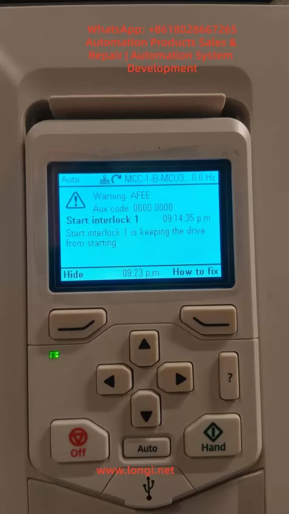
This paper provides a comprehensive analysis of the common “Start Interlock 1” fault in ABB ACH580 series variable frequency drives (VFDs), covering fault mechanisms, core causes, diagnostic procedures, and solutions. By integrating official technical manuals, engineering practice cases, and in-depth technical principles, a three-tier diagnostic system—”Signal Chain-Configuration Layer-System Level”—is constructed. This offers engineers in industrial and HVAC fields a full-process guide from basic troubleshooting to complex system debugging, facilitating rapid equipment restoration and preventing fault recurrence.
Introduction
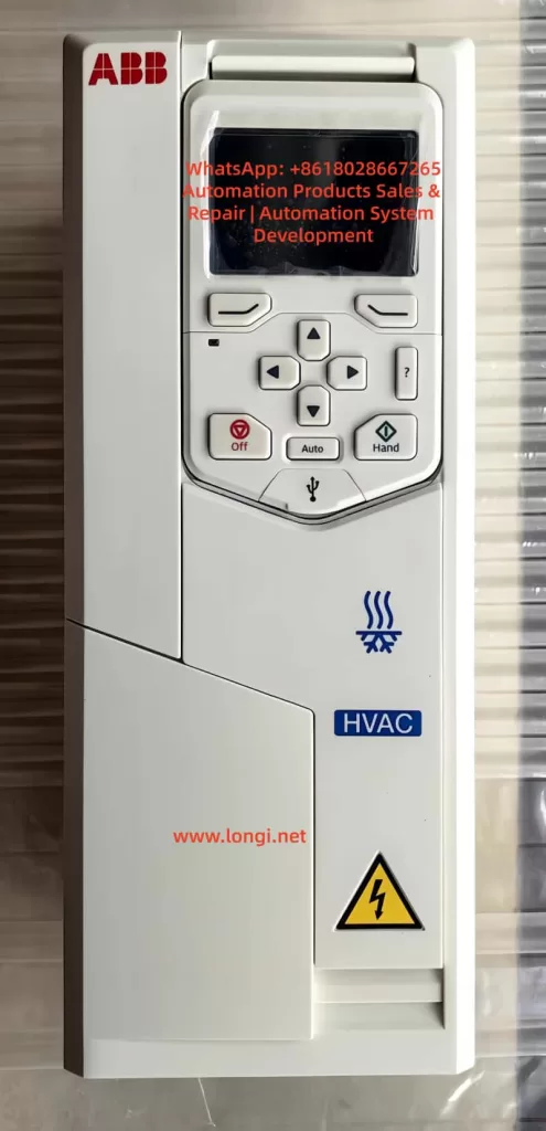
In modern industrial automation and HVAC systems, variable frequency drives serve as the core equipment for motor control, with their stability directly determining production efficiency and energy consumption. The ABB ACH580 series VFDs are widely used in load scenarios such as fans, pumps, and compressors due to their high efficiency, energy savings, and reliability. However, the “Start Interlock 1” fault is one of the high-frequency issues that prevent equipment from starting. This paper provides a systematic fault-solving methodology by dissecting the fault essence through technical analysis and case verification.
1. Fault Essence and Safety Mechanism Analysis
1.1 Definition and Function of “Start Interlock 1”
“Start Interlock 1” is an inherent safety protection logic in ABB ACH580 VFDs, designed to ensure that the drive starts the motor only when external conditions are met. Its core function is to monitor preset digital input signals (default DI4 terminal) or communication instruction states to determine whether the device is ready for startup. When the interlock signal is invalid, the VFD immediately blocks the startup process, displays a warning on the panel, and accompanies it with an AFEE code.
1.2 Design Logic of the Safety Mechanism
This protection mechanism adheres to the IEC 61800-5-1 functional safety standard and falls under the category of “Safety-Related Stop Functions” (SRS). Its design logic can be summarized as an “AND gate control”:
Condition 1: The drive has no hardware faults (e.g., overcurrent, overvoltage, overheating, or other critical errors).
Condition 2: The external startup instruction is valid (e.g., panel “Hand” mode startup, remote DI signal, or bus control word).
Condition 3: The “Start Interlock 1” signal is valid (default high level 1 or communication bit enabled).
Only when all three conditions are satisfied can the VFD proceed to the startup sequence; otherwise, interlock protection is triggered.
2. In-Depth Analysis of Core Fault Causes
According to ABB technical manuals and engineering case statistics, “Start Interlock 1” faults can be categorized into four main types:
2.1 External Signal Chain Anomalies (45%)
2.1.1 Digital Input Terminal Faults
Wiring Issues: Loose, oxidized, or damaged DI4 terminal connections can lead to signal disconnections, common in vibrating environments (e.g., pump rooms) or frequent plugging/unplugging scenarios.
Power Supply Conflicts: External sensors (e.g., pressure switches, limit switches) may have power supply logic conflicts with the VFD’s DI terminals (e.g., sensor output is PNP, while VFD DI is configured for NPN input).
Interference Impact: Analog signal cables running parallel to power cables can cause electromagnetic interference (EMI), leading to signal misinterpretation, especially in systems with high-frequency harmonics from VFD speed control.
2.1.2 External Safety Device Activation
In HVAC systems, the interlock signal is often linked to critical safety devices. Typical triggering scenarios include:
Pressure Protection: Low-pressure switches at pump inlets or high-pressure safety valves at outlets activating.
Temperature Interlocks: Freeze protection switches in heat exchangers or motor winding over-temperature protections triggering.
Mechanical Limits: Unreset end-limit switches on damper actuators or belt breakage detection sensors activating.
Fire Signals: Building fire systems forcing the shutdown of air conditioning units (e.g., FAS system sending a stop command).
2.2 Parameter Configuration Errors (30%)
2.2.1 Incorrect Interlock Source Selection
Parameter 20.41 (Start interlock 1 source) defines the interlock signal source. Common configuration errors include:
Source Mismatch: Using DI5 terminal while incorrectly setting it to “DI4.”
Communication Source Conflicts: In Modbus or BACnet control modes, mistakenly setting the interlock source to “digital input” instead of “communication control word bit.”
Logic Level Errors: Setting parameter 20.42 (Start interlock 1 active level) to “high level active” while the external sensor outputs a low-level signal.
2.2.2 Multi-Pump/PFC System Configuration Anomalies
In constant pressure water supply or multi-fan linkage systems (PFC function), interlock faults are often related to the following parameters:
Node Configuration Errors: Setting parameter 76.22 (PFC number of nodes) to 3 pumps while only 2 are online, causing master-slave communication timeouts.
Run Permissive Timeout: Setting parameter 76.64 (Run permissive timeout) too short (e.g., default 5 seconds) while the external PLC startup instruction is delayed, triggering a timeout interlock.
Synchronization Parameter Inconsistencies: Failure to unify parameters 76.101 (PFC sync word 1) and 76.102 (PFC sync word 2) across multiple pumps, leading to node state misinterpretation.
2.3 Communication and Control Logic Faults (15%)
2.3.1 Fieldbus Communication Anomalies
In industrial Ethernet (e.g., Profinet) or Modbus RTU control scenarios, communication interruptions or data errors can cause interlock signal loss:
Bus Physical Layer Faults: Damaged network cables, missing terminal resistors (Profinet requires 110Ω terminal resistors), or poor grounding leading to common-mode interference.
Protocol Data Errors: Incorrect control word bit definitions (e.g., Modbus register address 0x0002 Bit3 for interlock not set to 1).
Slave Station Timeout: When the VFD acts as a slave, if the master station (e.g., PLC) communication cycle exceeds the parameter 32.05 (Bus timeout) setting (default 2000ms), a “communication interlock failure” is triggered.
2.3.2 Control Mode Switching Conflicts
Frequent switching between “Auto” and “Hand” modes can cause logic conflicts if the external control system does not synchronously update the interlock signal:
Example: In “Auto” mode, the PLC controls the interlock signal. Switching to “Hand” mode without the PLC sending a release command results in a persistently invalid interlock signal.
2.4 Hardware and Power Supply Faults (10%)
2.4.1 Internal VFD Faults
DI Terminal Module Damage: Surge voltages (e.g., lightning strikes) or overcurrent can burn out digital input optocouplers, common in outdoor equipment without surge protection devices (SPDs).
CPU Board Logic Errors: Main control board program crashes or EEPROM parameter corruption can be verified via “factory reset” (parameter 96.06).
Power Module Anomalies: Excessive ripple (>50mV) in the auxiliary power supply (+24V DC) can cause misinterpretation of DI signal detection circuits.
2.4.2 External Power Supply Fluctuations
Undervoltage Impact: When the AC 220V control power supply drops below 180V, the internal pull-up resistor voltage division in the DI terminal becomes insufficient, causing the signal to be misinterpreted as “low level.”
Grounding Faults: System grounding resistance exceeding the standard (>4Ω) can lead to common-mode voltage interference in the DI signal detection circuit.
3. Systematic Diagnostic Process and Tools
3.1 Basic Principles of Fault Diagnosis
Follow a “simple-to-complex, external-to-internal” troubleshooting logic, prioritizing the exclusion of external factors (wiring, power supply, external devices) before checking parameter configurations, and finally considering hardware faults. The “bisection method” is recommended for localization: first determine the interlock source state via panel monitoring parameters, then segmentally test the signal chain.
3.2 Basic Troubleshooting Tools and Steps
3.2.1 Panel Monitoring and Parameter Reading
Status Parameter Query:
Enter parameter 10.02 (DI delayed status) to view the interlock-related DI terminal state (e.g., DI4 displaying “0” indicates an invalid signal).
Check parameter 06.18 (Drive status word 2), where Bit4 (Start interlock 1 active) being “0” indicates an unsatisfied interlock.
In multi-pump systems, parameter 76.02 (PFC status word) Bit0 (Run permissive active) can determine the system-level interlock state.
Event Log Analysis:
Enter parameters 04.40 (Latest fault code) and 04.41 (Fault time) to confirm the fault occurrence time and associated events (e.g., whether accompanied by “Overvoltage” or “Communication loss”).
3.2.2 Electrical Test Tool Applications
Multimeter: Measure the voltage between the DI terminal and COM (for PNP input, the signal should be +24V when valid and 0V when invalid).
Oscilloscope: Detect DI signal waveforms to identify glitches or interference (normal signals should have no ripple exceeding 50mV).
Megohmmeter: Measure DI cable insulation resistance (should be >10MΩ) to exclude grounding faults.
3.3 Advanced Diagnostics: Signal Chain Integrity Testing
Using the default DI4 terminal as an example, construct a “Signal Chain Test Table”:
Test Node
Test Method
Normal Standard
Abnormal Handling Suggestions
External Sensor Output
Short-circuit sensor contacts and measure output voltage
In building automation systems (BAS), the following steps are recommended for troubleshooting:
BACnet Communication Test: Monitor the BV20 (Start interlock 1) object status via ABB Drive composer software to confirm whether the BAS system sends “1” (allow startup).
Linkage Logic Verification: In BAS programming software (e.g., Tridium Niagara), check whether interlock conditions (e.g., “damper fully open” AND “fire signal normal”) are met.
Timeout Parameter Adjustment: If BAS instruction delays occur, extend parameter 76.64 (Run permissive timeout) to 10 seconds.
4. Full-Scenario Solutions and Cases
4.1 External Signal Chain Repair Solutions
Case 1: Loose DI Terminal in a Pump Room Causing Interlock Failure
Fault Phenomenon: In a residential secondary water supply system, the ACH580 VFD reports “Start Interlock 1,” with the panel showing DI4 status as 0.
Troubleshooting Process:
Measured voltage between DI4 and COM as 0V (normal should be 24V).
Inspected the terminal block and found a loose DI4 terminal screw with oxidized cables.
Solution:
Cleaned terminal oxidation with fine sandpaper, re-crimped cables, and tightened screws.
Added anti-loosening markers at the terminal block and established a monthly inspection plan.
Result: Fault disappeared after restart, with stable operation.
Case 2: Electromagnetic Interference Causing Signal Misinterpretation
Fault Phenomenon: In a shopping mall air conditioning unit, the VFD randomly reports interlock faults with DI signal fluctuations during operation.
Solution:
Replaced DI signal lines with twisted-pair shielded cables, grounding the shield at the VFD side.
Adjusted cable routing to maintain a >30cm distance from power cables.
Added an RC filter circuit (100Ω resistor + 104 capacitor) before the DI terminal.
Result: Interference eliminated, with no recurrence of faults.
Case 3: PFC Parameter Configuration Errors in a Multi-Pump System
Fault Phenomenon: In a factory constant pressure water supply system (3 pumps), pump #2 reports “Start Interlock 1” and cannot participate in rotation.
Troubleshooting Process:
Checked parameter 76.22 (PFC number of nodes) set to “3” but parameter 76.25 (Number of motors) set to “2.”
Found inconsistent parameter 76.101 (Sync word 1) between master and slave stations (master 0x1234, slave 0x1235).
Solution:
Unified settings: 76.22=3, 76.25=3.
Synchronized all pump parameters via Drive composer software (checked “PFC synchronization” option).
Result: System restarted normally with 3 pumps rotating, and interlock fault resolved.
4.3 Hardware Fault Repair and Prevention
Case 4: DI Module Damage from Surge
Fault Phenomenon: In an outdoor fan VFD, a “Start Interlock 1” fault occurred after a thunderstorm, with no signal input at DI4 terminal.
Troubleshooting Process:
Measured DI4 terminal-to-ground resistance as 0Ω (normal should be infinite), indicating a burned-out optocoupler.
Solution:
Replaced the DI input module (model: ACH-0201).
Installed a surge protection device (Imax≥20kA, Up≤1.5kV) before the DI terminal.
Result: Module replacement restored signal, with no further damage during subsequent thunderstorms.
4.4 System-Level Interlock Logic Optimization
Case 5: Fire Linkage Interlock Design for a Hospital Cleanroom HVAC System
Requirement: When a fire signal is triggered, the VFD must immediately stop and prohibit restart (interlock locking).
Solution:
Parameter Configuration:
20.41=DI6 (fire signal input terminal).
20.42=low level active (DI6=0V during fire action).
20.45 (Start interlock stop mode)=1 (ramp stop).
External Circuit: Fire signal relay contacts are串联 (series-connected) to DI6 and COM to ensure reliable disconnection during fire action.
Effect: Upon fire signal trigger, the VFD stops with a 10-second ramp, and the interlock locks, requiring manual reset of the fire signal for restart.
5. Preventive Maintenance and Long-Term Reliability Enhancement
5.1 Regular Maintenance Plan (Recommended Cycles)
Daily Checks: Panel shows no interlock warnings, and DI signal states are normal (monitored via parameter 10.02).
Monthly Maintenance: Tighten DI terminal screws, measure insulation resistance, and clean VFD filters.
Quarterly Calibration: Calibrate DI signal detection thresholds using a signal generator (via Drive composer software).
Annual Inspection: Test surge protector performance and check grounding resistance (≤4Ω).
5.2 Design-Stage Optimization Recommendations
Hardware Selection: Prioritize DI terminals with built-in surge protection (e.g., ACH580-01 series).
Wiring Specifications: Use twisted-pair shielded cables for DI signals, with lengths ≤50 meters, and avoid parallel routing with VFD output cables.
Redundancy Design: Implement dual-loop inputs for critical interlock signals (e.g., fire, pressure protection) to enhance reliability.
Parameter Backup: Regularly back up parameters via USB or Drive composer to prevent configuration loss.
5.3 Intelligent Monitoring Solutions
Through the ABB Ability™ cloud platform or local SCADA system, implement a “interlock signal trend analysis” function:
Real-Time Monitoring: Track DI signal fluctuations and set threshold alarms (e.g., signal jitter >5 times/minute).
Fault Frequency Logging: Record interlock trigger frequencies and associated events to generate preventive maintenance reports.
Remote Parameter Adjustment: Enable remote parameter modification and fault reset to reduce on-site intervention time.
Conclusion
The “Start Interlock 1” fault is a direct reflection of the ACH580 VFD’s response to external system states, with its essence being a “mismatch between safety logic and actual operating conditions.” Resolving this fault requires engineers to possess a cross-disciplinary mindset encompassing “electrical + control + system” knowledge. The proposed “three-tier diagnostic system” (signal chain-configuration layer-system level) enables efficient problem localization. In the context of Industry 4.0, combining preventive maintenance with intelligent monitoring not only resolves existing faults quickly but also facilitates a transition from “reactive maintenance” to “proactive prevention,” ensuring long-term equipment reliability throughout its lifecycle.
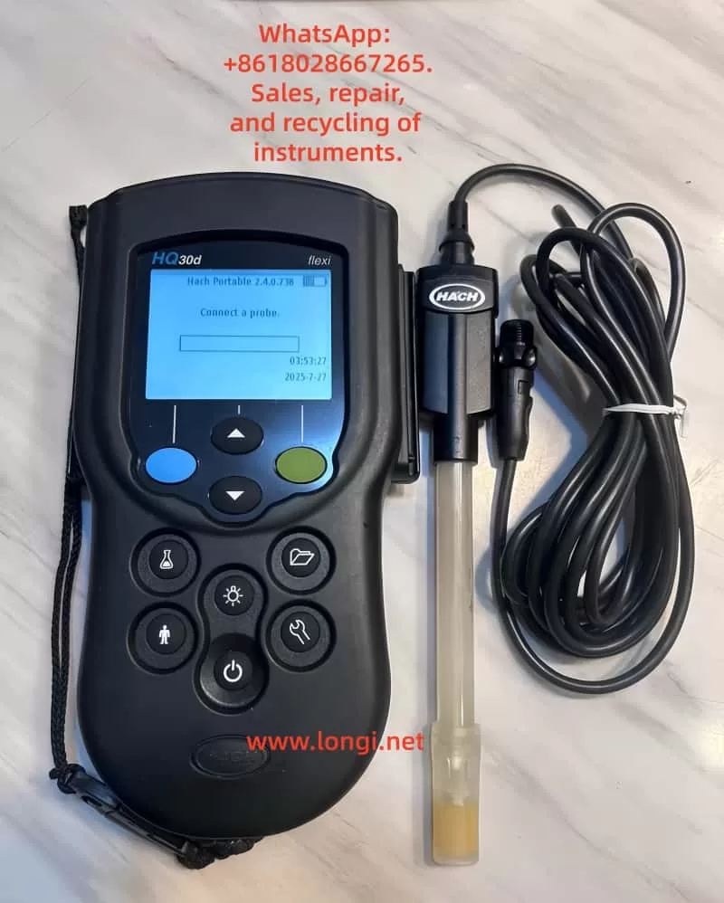
Chapter 1: Product Overview and Technical Specifications
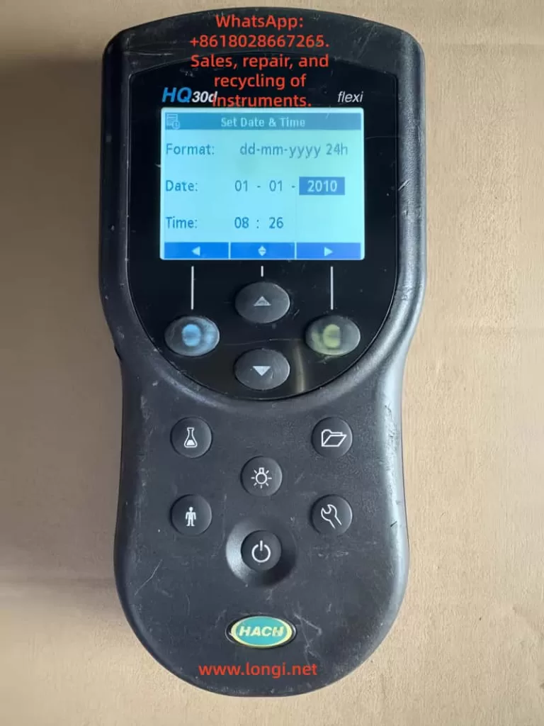
1.1 Introduction to HQ30D Series Products
The Hash HQ30D series dissolved oxygen meters are high-performance portable instruments developed by Hash Company. Utilizing advanced polarographic sensor technology, these meters are widely applied in environmental monitoring, wastewater treatment, aquaculture, and scientific research. Renowned for their high precision, stability, and portability, the HQ30D series meets the dissolved oxygen measurement needs in various complex environments. The series includes multiple models, allowing users to select the most suitable one based on their requirements. All models employ the same core measurement technology, ensuring consistent and reliable results.
1.2 Key Technical Specifications
Measurement Performance Indicators:
Measurement Range: 0–20 mg/L (ppm) or 0–200% saturation
Resolution: 0.01 mg/L or 0.1% saturation
Accuracy: ±0.1 mg/L or ±1.5% of the reading (whichever is greater)
Response Time: <30 seconds to reach 90% of the final value (at 25°C water sample)
Environmental Adaptability:
Operating Temperature Range: 0–50°C
Storage Temperature Range: -20–60°C
Protection Class: IP67 (fully dustproof and waterproof for short-term immersion)
Power Supply: 6-12V DC adapter or 4 AA alkaline batteries
Battery Life: Approximately 40 hours of continuous use (with new batteries)
Physical Characteristics:
Host Dimensions: 215 × 87 × 42 mm
Weight: Approximately 520 g (including batteries)
Display: 4-digit LCD with backlight
Chapter 2: Instrument Components and Installation
2.1 Standard Accessories List
Standard Configuration:
HQ30D host unit (1)
LDO101 dissolved oxygen electrode (1)
Power adapter (input: 100-240V AC, output: 6-12V DC)
4 AA alkaline batteries (pre-installed)
Portable carrying case (1)
User manual and certificate of conformity (1 each)
Maintain stable temperature in the measurement environment.
Accurately set compensation for high-salinity samples.
8.2 Handling Special Application Scenarios
Low Dissolved Oxygen Measurement:
Use fresh zero-oxygen solution for calibration.
Extend the stabilization time.
Use a flow measurement cell to reduce interference.
High-Salinity Water Samples:
Accurately measure and input the salinity value.
Consider using a high-salinity dedicated electrode.
Increase calibration frequency.
Flowing Water Body Measurement:
Use a flow adapter to fix the electrode.
Select representative measurement positions.
Avoid turbulence and bubble interference.
Conclusion
The Hash HQ30D series dissolved oxygen meters are comprehensive and user-friendly professional water quality analysis instruments. Through the systematic introduction in this guide, users should be able to master the various functions and maintenance points of the instrument proficiently. Correct usage methods and regular maintenance not only ensure the accuracy of measurement data but also extend the instrument’s service life.
As a key indicator in water quality monitoring, accurate dissolved oxygen measurement is crucial for water environment management. We hope this guide helps users fully leverage the performance advantages of the HQ30D dissolved oxygen meters, providing reliable technical support for water quality monitoring work. For further technical assistance, please feel free to contact Hash Company’s professional service team at any time.
Preface: Overview of Dissolved Oxygen Measurement Technology and Instruments
Dissolved oxygen (DO) is a crucial parameter in water quality monitoring, reflecting the self-purification capacity of water bodies and the health of ecosystems. The Hach Sension6 portable dissolved oxygen meter employs polarographic sensor technology, offering a measurement range of 0-20 mg/L (ppm) and 0-200% saturation, with an accuracy of 0.01 mg/L and 0.1% saturation. It supports dual power supply options (6-12V adapter or 4 AA alkaline batteries), complies with an IP67 protection rating, and features built-in data storage functionality. Data can be transferred to a computer or printer via an RS232 interface. This guide aims to assist users in comprehensively mastering the instrument’s operation, maintenance, and troubleshooting methods.
Chapter 1: Instrument Structure and Function Details
1.1 Instrument Composition and Standard Accessories
Take 150 mL of distilled water and shake vigorously for 5 minutes.
Alternatively, use a specially prepared saturated dissolved oxygen standard solution.
Calibration Steps:
Immerse the electrode in the saturated oxygen water.
Press the SETUP/CE key to enter the setup menu.
Select “Calibration” → “100% Cal”.
Wait for the reading to stabilize (display “Stabilizing…”).
Press READ/ENTER to confirm the full-scale value.
Press EXIT to exit the calibration mode.
3.3 Sample Measurement
Standard Measurement Process:
Immerse the electrode in the water sample to be tested.
Gently stir the electrode to keep the water sample flowing (avoid generating bubbles).
Wait for the reading to stabilize (about 30-60 seconds).
Press the CONC% key to switch between mg/L and % saturation display.
Record the measurement result.
Notes:
Avoid direct sunlight on the sample during measurement.
Keep the temperature of the water sample stable (temperature changes affect dissolved oxygen).
For high-salinity samples, set the salinity compensation.
3.4 Salinity and Barometric Pressure Compensation
Salinity Compensation Setting:
Press SETUP/CE to enter the setup menu.
Select the “Salinity” option.
Enter the salinity value of the sample (0-42 ppt).
Press READ/ENTER to confirm.
Barometric Pressure Compensation Setting:
Enter the setup menu and select “Barometer”.
Enter the local atmospheric pressure value (mmHg or inHg).
Or select “Auto” to automatically obtain barometric pressure data.
Press READ/ENTER to confirm.
Chapter 4: Advanced Function Applications
4.1 BOD Measurement Mode
BOD Measurement Steps:
Prepare a 300 mL BOD sample bottle.
Initially measure the DO value of the sample and record it.
Place the sample bottle in a 20°C incubator for 5 days.
After 5 days, measure the DO value again.
Calculate the BOD value (initial DO – final DO).
Notes:
Use a dedicated BOD bottle cap to prevent gas exchange.
Keep the incubation temperature constant at 20 ± 1°C.
For high-BOD samples, appropriate dilution may be required.
4.2 Data Storage and Retrieval
Data Storage:
After the measurement result is displayed, press the STORE key.
Enter the sample number (automatically or manually).
Press READ/ENTER to confirm storage.
Data Retrieval:
Press the RECALL key to enter the data review menu.
Use the ▲/▼ keys to select the sample number.
Press READ/ENTER to view detailed data.
Press TIME/DATE to view the storage time.
Data Management:
Can store up to 99 sets of measurement data.
Supports deleting a single set of data by number.
Can delete all stored data at once.
4.3 Data Output and Printing
RS232 Interface Connection:
Use the dedicated data cable to connect the instrument to a computer/printer.
Set the communication parameters (9600 baud rate, 8 data bits, no parity).
Press the PRINT key to send data.
Printing Options:
Print the current measurement value.
Print specified stored data.
Print all stored data.
Computer Connection:
Install the HachLink™ software.
Set up a hyperterminal to receive data.
Enable automatic data collection and storage.
Chapter 5: Instrument Maintenance and Troubleshooting
5.1 Daily Maintenance Points
Electrode Maintenance:
Regularly replace the electrolyte and membrane (recommended every 1-2 months).
Clean the electrode surface to avoid contamination.
Keep the electrode moist during short-term storage.
Store the electrode dry during long-term storage.
Instrument Cleaning:
Wipe the outer shell with a damp cloth.
Avoid using organic solvents.
Keep the keyboard and interface dry.
Calibration Recommendations:
Perform zero calibration before using the instrument each day.
Perform full-scale calibration once a week.
Recalibrate after replacing the electrolyte or membrane.
5.2 Common Faults and Troubleshooting
Display Problems:
No display: Check battery installation and power connection.
Blurry display: Adjust the contrast or replace the batteries.
“LOW BATTERY”: Replace all 4 batteries.
Measurement Abnormalities:
Unstable readings: Check the electrode connection and clean the electrode.
Slow response: Replace the electrolyte and membrane.
Calibration failure: Check the calibration solution and confirm the electrode status.
Error Codes:
Err 1: Sensor failure, check the electrode connection.
Err 2: Out of measurement range, dilute the sample.
Err 3: Calibration error, recalibrate.
Chapter 6: Safety Regulations and Quality Assurance
6.1 Safety Operation Regulations
Danger Warnings:
Do not use Ni-Cd rechargeable batteries as there is a risk of explosion.
Avoid contact of the electrode with strong acid and alkali solutions.
Do not immerse the instrument in water (although it has an IP67 protection rating).
Operation Precautions:
Wear protective equipment when handling chemical reagents.
Use standard solutions according to the instructions.
Dispose of used electrolyte as hazardous waste.
6.2 Quality Assurance and Service Support
Warranty Policy:
Standard warranty period is 1 year (from the date of shipment).
Covers material and workmanship defects.
Unauthorized disassembly will void the warranty.
Maintenance Services:
Users are not allowed to repair any parts other than the batteries by themselves.
Contact an authorized service center for handling.
Provide the instrument model and serial number when requesting maintenance.
Chapter 7: Practical Application Tips
7.1 Tips for Improving Measurement Accuracy
Sample Handling:
Avoid vigorous shaking to prevent bubble generation.
Keep the sample temperature stable.
Allow the electrode to acclimate to the sample temperature before measurement.
Electrode Maintenance:
Regularly replace the electrolyte and membrane.
Keep the membrane moist during storage.
Clean the electrode gently with a soft cloth.
Environmental Control:
Avoid strong electromagnetic interference.
Keep the measurement environment temperature stable.
Set the correct salinity compensation for high-salinity samples.
7.2 Handling Special Application Scenarios
Low Dissolved Oxygen Measurement:
Use zero calibration to improve accuracy at the low end.
Extend the stabilization time.
Avoid contact between the sample and air.
High-Salinity Water Samples:
Accurately set the salinity compensation value.
Consider using a dedicated high-salinity electrode.
Increase the calibration frequency.
Flowing Water Body Measurement:
Ensure sufficient contact between the electrode and the water.
Use a flow cell attachment.
Avoid measurement positions with eddies or bubbles.
Conclusion
The Hach Sension6 portable dissolved oxygen meter is a fully functional and easy-to-operate professional water quality analysis instrument. Through the systematic introduction in this guide, users should be able to proficiently master all functions of the instrument, from basic operations to advanced applications. Correct operation methods and regular maintenance can not only ensure the accuracy of measurement data but also extend the service life of the instrument. When encountering problems that cannot be resolved, promptly contact the professional technical service personnel of Hach Company to avoid improper operation causing instrument damage or data loss.
Dissolved oxygen monitoring plays an irreplaceable role in water environment protection, aquaculture, and sewage treatment. It is hoped that this guide can help users fully leverage the performance advantages of the Sension6 portable dissolved oxygen meter, providing reliable technical support for water quality monitoring work and jointly safeguarding the health of our water environment.