
I. Introduction
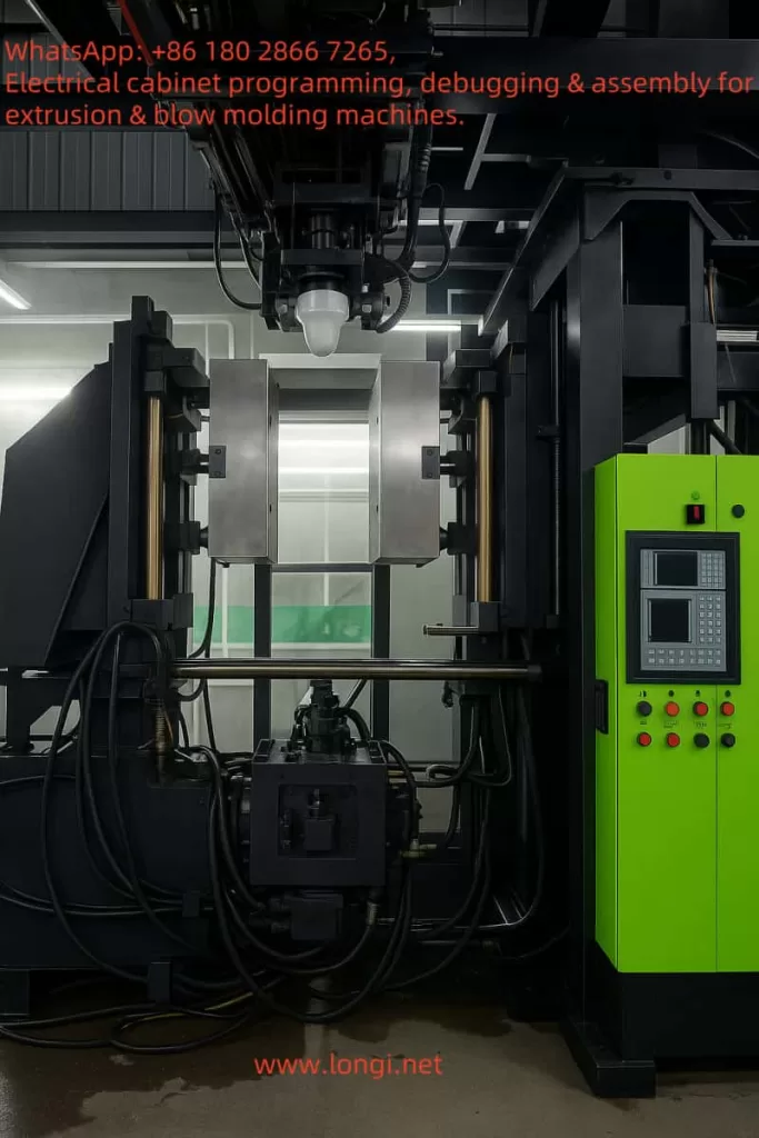
Blow molding machines are critical equipment for producing hollow plastic products (such as PE bottles and containers), with processes involving extrusion, clamping, blow molding, cooling, and mold opening. The Parker 590+ DC drive, with its precise speed and torque control capabilities, is particularly well-suited for controlling DC motors in blow molding machines. This document elaborates on the application of the 590+ drive in PE material blow molding machines, covering motor functions, wiring schemes, parameter settings, control system integration, and textual descriptions of electrical wiring diagrams and control schematics.
II. Analysis of Motor Functions in Blow Molding Machines
The process flow of blow molding machines (especially for PE material extrusion blow molding) includes:
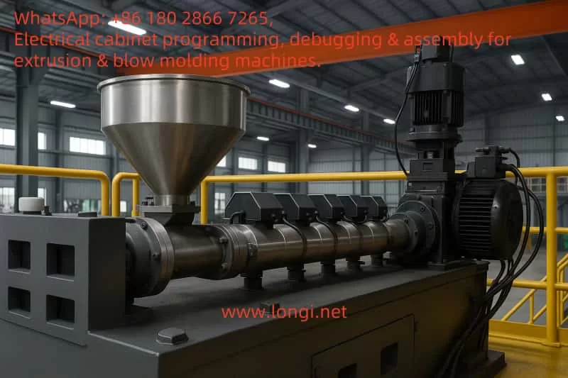
- Extrusion: Plastic pellets are melted through the extruder screw to form a tubular parison.
- Clamping: The mold closes to clamp the parison.
- Blow Molding: Air is injected into the parison to expand it into shape.
- Cooling: The molded product is cooled.
- Mold Opening: The mold is opened to remove the finished product.
Motor Functions
Based on the blow molding process, the following motors are suitable for use with the 590+ DC drive:
- Extruder Motor:
- Function: Drives the screw to control the plastic melting and extrusion speed.
- Requirements: Precise speed control, smooth acceleration/deceleration, and overload protection.
- Reason: PE materials require a stable extrusion speed to ensure uniform parison, emphasizing the need for high torque and precise speed control in the extruder.
- Clamp Unit Motor:
- Function: Controls the opening and closing of the mold.
- Requirements: Rapid response and precise speed or position control.
- Reason: Quick and accurate mold movements can improve production efficiency, requiring precise control of the clamping system.
- Other Motors (such as conveying and blow molding) typically use AC motors or pneumatic/hydraulic systems and are not suitable for the 590+ DC drive.
Motor Specifications (Based on User Input)
- Rated Voltage: 440V
- Rated Current: 25.1A
- Power: 15kW
- Speed: 1500 rpm
- Field: Field current not provided; assumed to use voltage control mode.
Assumption: The extruder motor uses the above specifications, while the clamp unit motor specifications may differ (e.g., 10A, assumed value) and need to be adjusted according to the actual nameplate.
III. Application Design of the 590+ DC Drive
1. Application Positions and Functions
(1) Extruder Motor
- Control Mode: Speed Control Mode (Speed Setpoint).
- Functions:
- Precisely control the screw speed to ensure uniform melting of PE materials.
- Maintain stable extrusion through PID control.
- Use Ramp function for smooth start/stop.
- Implementation: The drive receives a 0-10V speed reference signal from the PLC and feeds back the actual speed via an encoder or DC generator.
(2) Clamp Unit Motor
- Control Mode: Speed Control Mode (Speed Setpoint) or Position Control Mode (if supported).
- Functions:
- Control the rapid closing and opening of the mold.
- Ensure precise movements to reduce mechanical shock.
- Implementation: The drive receives open/close commands from the PLC and may use limit switches for position control.
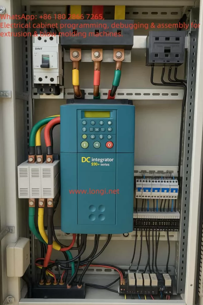
2. Wiring Scheme
(1) Motor Connections
- Extruder Motor:
- Armature: Connect to the drive’s A1 (positive)/A2 (negative) terminals.
- Field: If internally powered, no connection is needed; if externally powered, connect to FL1/FL2 terminals (refer to manual).
- Clamp Unit Motor: Same as above; confirm based on actual motor specifications.
(2) Control Signal Connections
- Speed Reference:
- PLC analog output (0-10V) connected to the A4 terminal (ANIN3).
- Ensure signal shielding to reduce noise.
- Start/Stop:
- PLC digital output connected to the C3 terminal (DIGN2, start).
- PLC digital output connected to the C4 terminal (DIGN3, stop, or use a single signal).
- Feedback:
- Encoder connected to the drive’s encoder input terminals.
- DC generator connected to the TB terminal.
- Communication:
- P3 port connected to the PLC communication interface (e.g., RS-485) for data exchange.
(3) Power Connections
- Main Power: Three-phase AC power (380V or matching voltage) connected to the L1/L2/L3 terminals.
- Control Power: 24V DC connected to the C9 (+24V)/C10 (0V) terminals.
Wiring Precautions
- Use shielded cables to reduce electromagnetic interference.
- Ensure good grounding and compliance with safety standards.
- Refer to the wiring diagram in Appendix L of the manual.
3. Parameter Settings
(1) Extruder Motor
The following parameters are based on the motor nameplate (440V, 25.1A):
| Parameter Name | Label | Setting Value | Range | Default | Notes |
|---|---|---|---|---|---|
| ARMATURE V CAL. | 20 | 1.0353 | 0.9800 to 1.1000 | 1.0000 | Voltage switch set to 425V |
| CUR. LIMIT/SCALER | 15 | 100.00% | 0.00 to 200.00% | 100.00% | Corresponds to 25.1A |
| MAIN CURR. LIMIT | 421 | 100.00% | 0.00 to 200.00% | 200.00% | Adjustable as needed |
| FIELD CONTROL MODE | 209 | VOLTAGE | VOLTAGE/CURRENT | VOLTAGE | Voltage control mode |
| RATIO OUT/IN | 210 | 90.00% | 0.00 to 100.00% | 90.00% | Initial field voltage ratio |
| SPEED FBK SELECT | 10 | ENCODER | Multiple options | – | Assume encoder used |
| MODE | 1 | Speed Setpoint | Multiple modes | – | Speed control mode |
| RAMP RATE (Accel) | 2 | 5.0 seconds | 0.1 to 600.0 seconds | – | Smooth acceleration |
| RAMP RATE (Decel) | 3 | 5.0 seconds | 0.1 to 600.0 seconds | – | Smooth deceleration |
(2) Clamp Unit Motor
Assuming a current of 10A, other parameters are similar:
| Parameter Name | Label | Setting Value | Range | Default | Notes |
|---|---|---|---|---|---|
| ARMATURE V CAL. | 20 | 1.0353 | 0.9800 to 1.1000 | 1.0000 | Voltage switch set to 425V |
| CUR. LIMIT/SCALER | 15 | 100.00% | 0.00 to 200.00% | 100.00% | Corresponds to 10A |
| MAIN CURR. LIMIT | 421 | 100.00% | 0.00 to 200.00% | 200.00% | Adjustable as needed |
| FIELD CONTROL MODE | 209 | VOLTAGE | VOLTAGE/CURRENT | VOLTAGE | Voltage control mode |
| RATIO OUT/IN | 210 | 90.00% | 0.00 to 100.00% | 90.00% | Initial field voltage ratio |
| SPEED FBK SELECT | 10 | ENCODER | Multiple options | – | Assume encoder used |
| MODE | 1 | Speed Setpoint | Multiple modes | – | Speed control or position control |
| RAMP RATE (Accel) | 2 | 2.0 seconds | 0.1 to 600.0 seconds | – | Rapid acceleration |
| RAMP RATE (Decel) | 3 | 2.0 seconds | 0.1 to 600.0 seconds | – | Rapid deceleration |
Setting Steps:
- Enter the configuration mode via MMI (CONFIGURE ENABLE = ENABLED).
- Set the above parameters, referring to the manual’s menu system.
- Save the parameters (CONFIGURE ENABLE = DISABLED).
4. Control System Integration
(1) PLC Selection
- Recommendation: Siemens S7-1200 (compact, suitable for small to medium-sized blow molding machines) or S7-300 (suitable for large equipment).
- Functions:
- Control the process flow (extrusion, clamping, blow molding, mold opening).
- Send analog signals (speed reference) and digital signals (start/stop).
- Receive feedback from the drive (speed, current, faults).
- Modules:
- Analog output module (e.g., EM 231, 0-10V).
- Digital output module (e.g., EM 222).
- Communication module (e.g., RS-485).
(2) HMI Selection
- Recommendation: Siemens KTP700 Basic or Allen-Bradley PanelView Plus.
- Functions:
- Display extrusion speed, motor current, and fault status.
- Provide start/stop buttons and speed setting interface.
- Alarm management.
- Interface Example:
- Home Page: Display running status, speed, current.
- Settings Page: Adjust extrusion speed, clamping speed.
- Alarm Page: Display drive fault codes.
(3) Industrial PC (Optional)
- Recommendation: Siemens Simatic IPC477E or Beckhoff CX5130.
- Functions:
- Recipe management (store parameters for different PE products).
- Data logging (production data, fault logs).
- Applicable Scenarios: Large production lines or when advanced automation functions are required.
(4) Control Logic
- PLC Program:
- Main Cycle: Execute in process order (extrusion → clamping → blow molding → cooling → mold opening).
- Extruder:
- On startup, set speed reference (e.g., 50%) and activate the C3 terminal.
- On shutdown, deactivate C3 and set speed to 0.
- Clamp Unit:
- Before blow molding, send a close command (speed 100%).
- After blow molding, send an open command (speed -100% or reverse).
- Example Logic (Text Description):
- Press the “Start” button:
- Output speed reference (Q0.0, 0-10V) to A4.
- Activate C3 (Q0.1, start).
- Clamping phase:
- Output clamping speed (Q0.2, 0-10V) to the clamp drive’s A4.
- Activate clamp C3 (Q0.3, start).
- Press the “Start” button:
5. Electrical Wiring Diagram and Control Schematic
(1) Extruder Wiring Diagram (Text Description)
[Three-phase power 380V] --> [L1/L2/L3] --> [590+ input terminals][24V DC power] --> [C9(+24V)/C10(0V)] --> [590+ control power][Extruder motor armature] --> [A1/A2] --> [590+ output terminals][Extruder motor field] --> [FL1/FL2] --> [590+ field terminals] (if externally powered)[PLC analog output 0-10V] --> [A4(ANIN3)] --> [590+ speed reference][PLC digital output] --> [C3(DIGN2)] --> [590+ start][PLC digital output] --> [C4(DIGN3)] --> [590+ stop][Encoder] --> [Encoder input] --> [590+ feedback](2) Clamp Unit Wiring Diagram (Text Description)
[Three-phase power 380V] --> [L1/L2/L3] --> [590+ input terminals][24V DC power] --> [C9(+24V)/C10(0V)] --> [590+ control power][Clamp motor armature] --> [A1/A2] --> [590+ output terminals][Clamp motor field] --> [FL1/FL2] --> [590+ field terminals] (if externally powered)[PLC analog output 0-10V] --> [A4(ANIN3)] --> [590+ speed reference][PLC digital output] --> [C3(DIGN2)] --> [590+ start][PLC digital output] --> [C4(DIGN3)] --> [590+ stop][Limit switch] --> [Digital input] --> [590+ position feedback](3) Control Schematic (Text Description)
[Operator] --> [HMI KTP700][HMI] --> [PLC S7-1200][PLC] --> [Analog output Q0.0] --> [Extruder 590+ A4][PLC] --> [Digital output Q0.1] --> [Extruder 590+ C3][PLC] --> [Analog output Q0.2] --> [Clamp 590+ A4][PLC] --> [Digital output Q0.3] --> [Clamp 590+ C3][Extruder 590+] --> [Extruder motor] --> [Screw][Clamp 590+] --> [Clamp motor] --> [Mold][PLC] --> [Other controls] --> [Blow molding valve, cooling system]6. Implementation Steps
(1) Wiring
- Confirm the power supply voltage (380V or matching).
- Connect the motor armature (A1/A2) and field (FL1/FL2, if required).
- Connect the control power (C9/C10).
- Connect the PLC analog output to A4 and digital outputs to C3/C4.
- Connect feedback devices (encoder or DC generator).
- Connect the P3 port to the PLC communication interface.
(2) Parameter Setting
- Enter the MMI and set CONFIGURE ENABLE = ENABLED.
- Set parameters such as armature voltage, current limit, field mode, etc.
- Configure speed feedback and control mode.
- Save parameters and set CONFIGURE ENABLE = DISABLED.
(3) PLC and HMI Configuration
- Write the process control program in the PLC.
- Configure the HMI interface, adding status displays and control buttons.
- Test communication (PLC with the drive).
(4) Testing and Debugging
- Power on and check the drive status (no alarms).
- Start the extruder via the HMI and verify speed control.
- Test the clamp unit’s opening and closing to ensure accurate movements.
- Adjust parameters (e.g., Ramp time, PID gain) to optimize performance.
7. Precautions
- Safety: Power off before wiring and comply with electrical safety standards.
- Debugging: Test step-by-step to avoid motor overload or mechanical damage.
- PE Material Characteristics: Ensure extrusion speed is coordinated with temperature control.
8. Conclusion
By applying the Parker 590+ DC drive to the extruder and clamp unit of a blow molding machine, precise motor control can be achieved, improving the production efficiency and quality of PE products. The wiring scheme ensures reliable signal transmission, parameter settings match motor requirements, and PLC and HMI integration enable automated control. This scheme is a general design and may require fine-tuning based on specific equipment and processes.