
I. Background and Problem Description
In CNC machining center maintenance and commissioning, the calibration of the Z-axis reference point and tool change point is critical for ensuring the machine’s precision and stability.
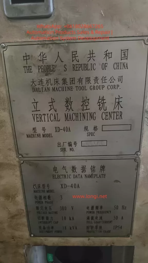
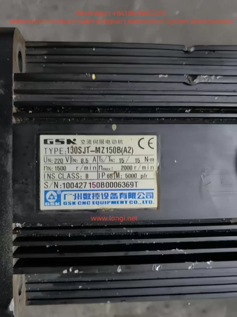
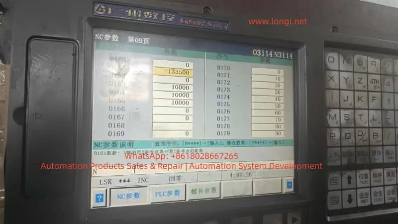
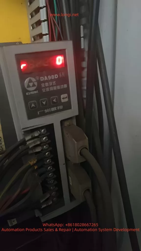
This article takes the XD-40A vertical machining center manufactured by Dalian Machine Tool Group as an example. The machine is equipped with a GSK983Ma-H CNC system, DA98D servo drive, and a Sanyo OIH 5000P/R incremental encoder.
The machine adopts an umbrella-type tool magazine, where the Z-axis must accurately position at the second reference point during tool change.
During routine maintenance, the Z-axis servo motor was replaced. After replacement, the machine could start and home normally, but an abnormality appeared during tool change (M06):
The Z-axis stopped about 3 mm higher than before, causing the spindle taper to fail to engage the tool holder. The operator had to manually lower the Z-axis by 3 mm to complete the tool change.
Although this deviation did not trigger any alarms, it seriously affected the reliability of automatic tool change and could lead to tool gripper misalignment, incomplete release, or even tool crashes.
II. System Structure and Signal Relationship Analysis
To solve the issue, it is essential to understand how the GSK983Ma-H system defines the Z-axis “reference point (home position).”
The Z-axis homing position is determined by two signals:
- Proximity switch signal (HOME/ORG) – used for coarse positioning;
- Encoder Z-phase signal (Z-phase) – used for fine positioning.
When the machine executes the “Home” (G28 Z0) command after power-up, the sequence is as follows:
- The Z-axis moves in the specified direction until it detects the proximity switch signal.
- The system records the pulse position at this point.
- After the proximity signal is released, the axis continues moving.
- When the next Z-phase pulse is detected, the system defines that position as the machine reference point (zero point).
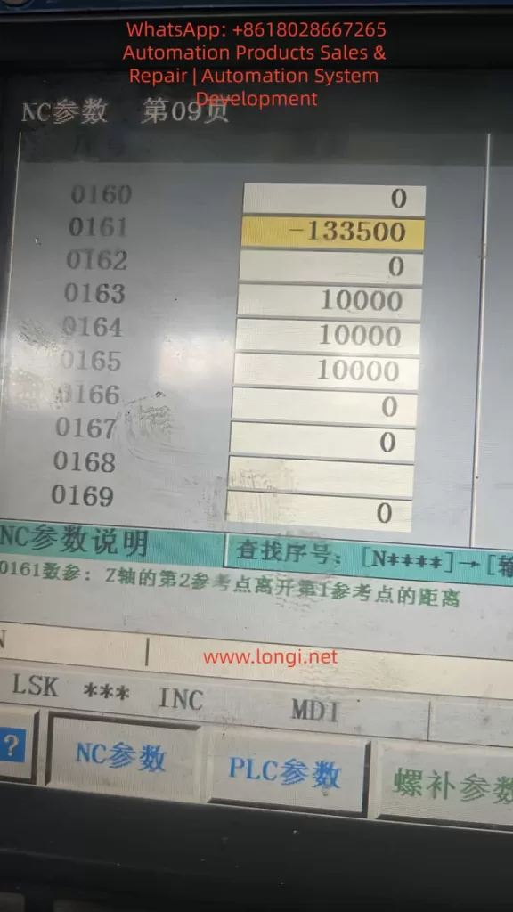
- Based on parameter 0161, the system then calculates the second reference point (e.g., tool change point).
Thus, the Z-axis zero position is not determined by the limit switch alone, but by the phase relationship between the proximity signal and the encoder Z-phase pulse.
III. Root Cause Analysis After Motor Replacement
In this case, the proximity switch, lead screw, and limit mechanism remained unchanged, yet a 3 mm tool change deviation occurred after replacing the motor.
The underlying causes are as follows:

1. Encoder Z-phase Signal Phase Difference
Even among identical motor models, the internal encoder Z-phase position relative to the rotor magnetic pole can vary slightly due to manufacturing tolerances.
When the system executes “find proximity then find Z-phase,” a phase delay or advance changes the zero-point position.
For a 5000-line encoder:
[
5\text{ mm / rev} \Rightarrow 1 \text{ Z pulse = 5 mm}
]
If the Z-phase triggers 0.6 turns later, the system’s reference point shifts upward by approximately 3 mm.
2. Coupling Installation Angle Deviation
If the motor–lead screw coupling is reassembled with a slight angular misalignment or reversed orientation, the timing between the proximity and Z-phase signals changes, causing a fixed offset.
3. Second Reference Point Parameter Not Recalibrated
Parameter 0161 in the GSK system defines the distance between the first and second reference points.
If the old value is retained after encoder replacement, the stored Z-phase relationship becomes invalid, resulting in a tool change height deviation.
4. Servo Phase Angle or Polarity Mismatch
If the servo drive’s electrical phase offset (in DA98D) is not re-calibrated, it can cause inconsistent homing. However, such errors typically lead to random deviations, not a consistent 3 mm offset.
IV. Parameter Framework and Signal Interaction
The GSK983Ma-H system controls Z-axis referencing using several key parameters:
| Parameter | Description | Function |
|---|---|---|
| 0160 | Home direction | Defines positive or negative direction of homing |
| 0161 | Distance from 1st to 2nd reference point | Defines tool change position |
| 0162 | Home offset | Compensates fine homing deviation (if available) |
| 0163–0165 | Homing speeds | Control homing speed at each stage |
| 0171–0175 | Home switch logic | Defines trigger mode and direction |
Thus, the final tool change position can be expressed as:
[
Z_{tool} = Z_{prox} + ΔZ_{Z-phase} + P_{0161}
]
Any change in the above components—especially the Z-phase offset—will cause a physical shift in the tool change height.
V. Comparative Analysis of Available Solutions
When parameter modification (0161) is restricted by password protection, alternative methods must be considered.
Below is a comparison of practical options used in the field.
| Method | Principle | Application | Advantage | Risk |
|---|---|---|---|---|
| Modify 0161 | Adjusts tool change offset | If password available | Accurate and safe | Requires password |
| Adjust proximity switch | Shifts home reference mechanically | No password | Simple and direct | Changes all Z references |
| Change servo electronic gear ratio | Alters pulses per unit | Mismatch in lead screw | Fixes scaling | Affects entire travel accuracy |
| Modify home offset (if available) | Software correction | Some versions only | No mechanical adjustment | Usually locked |
| Adjust motor phase | Alters encoder–rotor relationship | Encoder misalignment | Permanent correction | Complex, risky |
Conclusion:
- If password access is available, adjusting 0161 is best.
- If not, physically adjusting the proximity switch by 3 mm is the most practical.
- Avoid changing gear ratios unless lead screw or encoder specifications differ.
VI. Practical Solution Without Password Access
When the system password is unknown or locked, the following mechanical method effectively corrects the deviation.
1. Required Tools
Hex wrench, caliper or feeler gauge, insulation gloves, and a tool holder or alignment gauge.
2. Determine Adjustment Direction
- If Z-axis stops too high → move the proximity switch upward.
- If Z-axis stops too low → move the switch downward.
3. Adjustment Procedure
- Power off the machine.
- Loosen the Z-axis home switch screws.
- Move the switch up by approximately 3 mm.
- Tighten screws and power on.
- Re-home the Z-axis and test tool change.
4. Verification
Execute:
G28 Z0
M06 T1
Check if the spindle taper aligns with the tool gripper. Fine-tune the switch by ±0.5 mm if needed.
5. Update Work Coordinate
Since the machine reference has shifted, redefine the Z=0 in G54 by touching off the workpiece again.
VII. DA98D Drive Parameter Verification
To ensure that the deviation is not caused by drive scaling, verify the following parameters in the DA98D servo drive:
| Parameter | Function | Recommended | Description |
|---|---|---|---|
| P1.05 | Electronic gear numerator | 20000 | Encoder output per rev |
| P1.06 | Electronic gear denominator | 1 | 1:1 transmission |
| P2.04 | Home polarity | Depends on axis | Match direction |
| P4.01 | Auto phase calibration | Execute after motor replacement | Syncs magnetic poles |
Any incorrect electronic gear ratio can cause axis scaling errors and must be restored to 1:1.
VIII. Pulse Calculation for 3 mm Offset
Given:
- Lead screw pitch = 5 mm
- Encoder = 5000 PPR
- Pulses per revolution = 5000 × 4 = 20000
- Pulses per mm = 20000 ÷ 5 = 4000
Then:
[
3 \text{ mm} × 4000 = 12000 \text{ pulses}
]
To compensate for a 3 mm height difference, parameter 0161 should change by ±12000 pulses.
For example:
0161: -133500 → -145500
IX. Unlocking System Parameters
If full software correction is preferred, parameter protection can be disabled as follows:
- Navigate to:
SYSTEM → PARAM → NC PARAM - Press SET;
- When prompted, enter one of the following passwords:
| Password | Description |
|---|---|
| 983 | GSK default |
| 889 | Service engineer code |
| 1111 / 0000 | User level |
| 1314 / 8888 | OEM-defined |
After successful entry, “Protection Released” appears at the bottom of the screen, allowing parameter editing.
If unavailable, restart and hold DELETE or ALT+M during boot to enter the maintenance menu and disable “Parameter Protection.”
X. Understanding the Z-Axis Homing Logic
The following illustrates the Z-axis homing process:
 ↑ Z+
 │
 │       ┌────────────┐
 │       │ Proximity Switch │
 │       └────────────┘
 │                ↓ (continue)
 │               [Z-phase pulse]
 └──────────────────────────────→ Time
Explanation:
- Axis moves until proximity signal triggers;
- After signal release, continues to move;
- When Z-phase is detected, zero point is set;
- From that zero, parameter 0161 defines the tool change position.
If the Z-phase occurs later relative to the proximity switch, the zero point shifts upward, making the spindle stop higher during tool change.
By moving the proximity switch 3 mm upward, the zero point effectively moves downward by 3 mm, correcting the deviation.
XI. Key Lessons and Maintenance Practices
- Always re-calibrate reference points after replacing incremental encoders.
Even a small Z-phase shift can cause millimeter-level errors. - Back up all NC parameters before maintenance.
Parameter loss or mismatch is a frequent cause of deviation. - Prefer software compensation over mechanical adjustments.
Mechanical adjustments are practical but less precise. - Do not change electronic gear ratios arbitrarily.
They affect all axis scaling, not just tool change height. - Umbrella-type tool changers rely heavily on parameter 0161.
Incorrect values lead to failed or dangerous tool changes. - After adjustment, verify through a full test:
- Home the Z-axis;
- Execute tool change;
- Check gripper alignment;
- Recalibrate work coordinate (G54).
XII. Conclusion
This study analyzed a real case of Z-axis tool change deviation on an XD-40A vertical machining center equipped with GSK983Ma-H control and DA98D servo drives.
Through a detailed investigation of encoder Z-phase behavior, servo drive settings, and CNC reference logic, it was concluded that the 3 mm deviation was caused by a Z-phase timing difference, not mechanical misalignment.
When parameter modification is possible, adjusting parameter 0161 is the optimal solution.
When access is restricted, mechanically adjusting the proximity switch by 3 mm effectively compensates for the offset.
If hardware specifications differ, recalibration of the electronic gear ratio is necessary.
This case highlights that CNC positioning precision depends not only on mechanical accuracy but also on the synchronization between hardware signals and software logic.
A deep understanding of the system’s internal mechanisms allows technicians to restore functionality efficiently, accurately, and safely.