I. Introduction: When the Brain of the Drive Crashes
The Mitsubishi FREQROL-A700 inverter series is renowned for its high-performance vector control, stable communication capabilities, and comprehensive protection functions. It is widely used in CNC machines, plastic molding equipment, air compressors, hoists, and a variety of industrial automation lines.
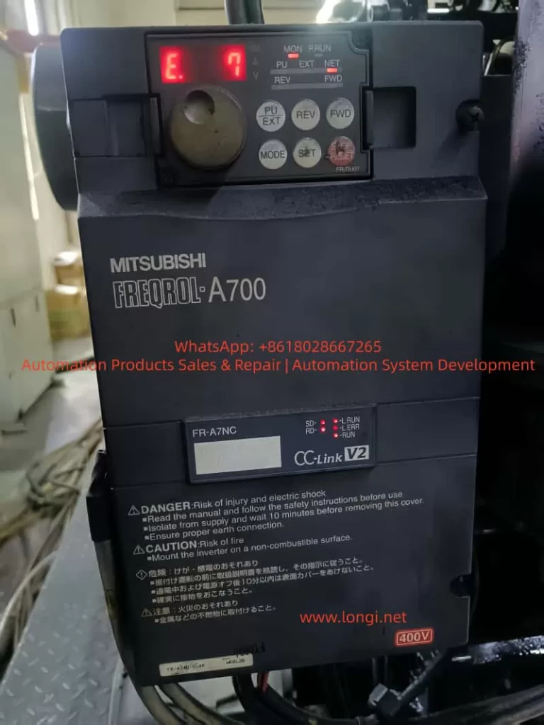
However, when the display shows “E.7” or “E.CPU”, the inverter immediately halts output, and the entire system comes to a standstill. This is often referred to by technicians as a “brain crash,” as it indicates a critical failure of the inverter’s central processing unit (CPU).

Among all protection codes, E.7 is one of the most severe. It typically signals that internal communication between control units has failed, logic processes have become unstable, or the CPU hardware itself has malfunctioned.
This article offers a comprehensive technical exploration of the E.7 (CPU Error) fault — its causes, diagnostic methods, hardware implications, repair solutions, and preventive measures — supported by real industrial case studies.
II. Understanding the Fault and System Logic
According to the FR-A700 User Manual (page 397):
E.6 / E.7 / E.CPU – CPU Error
When an internal CPU communication error occurs, the inverter stops output.
Inspection Point: Check if there are devices around the inverter that generate strong electrical noise.
Measure: If no external interference is found, contact the supplier or Mitsubishi service center.
This indicates that E.7 is a system-level protection event.
The inverter’s internal logic continuously monitors communication between the main CPU, gate driver interface, and memory/control buses. If any communication timeout or checksum failure occurs, the CPU triggers a protective shutdown to prevent unpredictable IGBT switching or hardware damage.
The main CPU fault logic in the FR-A700 involves:
- Abnormal communication between the main processor and gate drive circuits.
- Data corruption or response failure in EEPROM, ADC, or communication ICs.
- Watchdog timer reset caused by logic hang or power fluctuation.
When the watchdog detects that the CPU fails to respond within its monitoring period, the system declares a “CPU Communication Error” and displays E.7.

III. Technical Causes of the CPU Error
The E.7 fault generally stems from three major categories of issues:
- Electromagnetic interference (EMI)
- Power supply instability
- Internal control board failure
1. Electromagnetic Interference (EMI)
Industrial sites are rich in high-frequency noise sources — welding machines, large contactors, induction heaters, and switching power supplies. These generate voltage spikes and transient electromagnetic waves that couple into the control board’s circuits, disturbing the CPU clock or data bus.
Typical EMI sources include:
- Arc welders or high-frequency induction furnaces
- Contactors or solenoid valves switching nearby
- Control signal lines routed in parallel with power cables
- Improper or floating grounding systems
In such cases, E.7 may occur intermittently, often clearing after power cycling — a sign that transient interference is affecting the CPU.
Technical Recommendations:
- Separate control wiring from power cables (minimum 10 cm apart).
- Use twisted shielded cables for control and communication lines.
- Ground all shields at one single point only.
- Install proper EMI filters and ferrite cores on input lines.
2. Power Supply Fluctuations or Grounding Issues
The FR-A700 series contains multiple voltage rails — DC bus (≈540 VDC), control voltage (24 VDC), and logic voltage (5 VDC).
When any of these experience transient drops due to unstable input voltage, aging capacitors, or poor grounding, the CPU watchdog may trigger an internal reset, leading to an E.7 CPU Error.
Typical symptoms:
- E.7 appears immediately upon power-up
- Random alternation between E.6 and E.7
- Display flickering or panel freezing
Diagnostic Points:
- Measure three-phase input balance and verify stable voltage.
- Check DC bus voltage ripple — excessive ripple suggests degraded capacitors.
- Measure 24V and 5V supply rails; ensure no drop below tolerance.
- Inspect the grounding system — avoid shared return paths with external PLCs or IO devices.
3. Hardware Failure on Control or Power Board
If E.7 persists after confirming stable power and minimal EMI, the most likely cause is a hardware fault.
Common hardware-related sources:
- Damaged main CPU (e.g., Renesas or Mitsubishi custom MCU)
- Failed EEPROM or memory IC communication
- Broken optocouplers (HCPL-2631, etc.) between logic and driver circuits
- Poor connection between control board and power board
- Feedback interference caused by a shorted IGBT module
Observable signs:
- Instant E.7 alarm at power-up
- Unable to reset via panel or RES signal
- FR-Configurator2 communication fails
- No clock signal detected on the CPU oscillator
In this situation, replacing the control PCB or even the entire inverter is often the most efficient solution.
IV. Step-by-Step Diagnostic Procedure
A systematic diagnostic process can help quickly isolate the E.7 cause.
Step 1: Record and Observe
- Note when the error occurs (during start, stop, idle, or communication).
- Observe whether the fault happens after brief power loss.
- Check ambient temperature (CPU overheating can cause instability).
Step 2: Insulation and Ground Testing
- After disconnecting power and waiting at least 10 minutes, measure insulation resistance (>5 MΩ) between main terminals and ground.
- Ensure no short between control circuits and main circuit.
Step 3: Check for Interference and Grounding Issues
- Verify that PE grounding resistance is below 10 Ω.
- Ensure all power cables are symmetrical (balanced three-phase).
- Avoid “loop grounds” by ensuring star-point grounding topology.
- For RS-485 or CC-Link communication, ground the shield at one end only.
Step 4: Monitor Power Rails
- Use an oscilloscope to monitor 24V and 5V supplies; ensure minimal ripple (<100 mV).
- Confirm the DC bus is steady without oscillation when idle.
Step 5: Module-Level Inspection
- Re-seat the operation panel and connectors between boards.
- Examine ribbon cables for oxidation or loose pins.
- Swap with a known-good control board if available.
- If error persists → replace power board or complete drive.
V. Repair and Replacement Strategies
1. Component-Level Control Board Repair
Qualified service technicians can:
- Verify CPU clock oscillator output (16–20 MHz typical).
- Check watchdog timer pulse (ICs like 74HC123).
- Replace EEPROM, voltage regulators, or capacitors.
- Re-solder cracked joints and clean carbon residue.
- Add low-ESR capacitors (e.g., 47 µF × 2) near CPU power pins to enhance filtering.
2. Inverter Replacement and Parameter Recovery
When the board is irreparable:
- Use FR-Configurator2 to back up parameters before removing the unit.
- Install the new inverter, then restore parameters via copy function (Pr.990–Pr.999).
- Run auto-tuning (Pr.71, Pr.80–Pr.84) to recalibrate motor characteristics.
3. Environmental Hardening
For long-term stability:
- Add EMI filters or isolation transformers on input side.
- Install surge absorbers (MOVs) between R/S/T lines.
- Route control and power cables separately.
- Maintain good cabinet ventilation and cleanliness.
VI. Case Study: CPU Error in Injection Molding Machine
An FR-A740-22K-CHT inverter was used as the main drive in a plastic injection molding machine. The unit displayed E.7 intermittently; resetting restored operation temporarily.
Investigation findings:
- Three inverters were installed side-by-side in the same panel.
- Control signal cables ran parallel to motor leads.
- Ground connections were multi-pointed, creating loops.
- Heavy dust on control board and fan filter.
Corrective actions:
- Re-routed control cables with shielded twisted pairs.
- Implemented star-point grounding.
- Added 100 µF capacitor to 5V rail on control board for ripple suppression.
- Cleaned dust and re-seated connectors.
After these measures, the machine ran for 72 hours continuously without reoccurrence.
Conclusion: E.7 was caused by EMI-induced communication loss rather than true CPU failure.
VII. Relationship Between Related Error Codes
| Code | Description | Meaning | Correlation |
|---|---|---|---|
| E.6 | CPU Communication Error A | Communication loss in main logic channel | Often co-occurs with E.7 |
| E.7 | CPU Communication Error B | Internal bus or logic timing fault | May escalate to E.CPU |
| E.CPU | CPU Hardware Fault | CPU self-check failure or watchdog timeout | Severe or persistent E.6/E.7 |
If E.6, E.7, and E.CPU alternate rapidly, it typically indicates either a logic power fault or crystal oscillator failure.
VIII. Preventive Engineering Practices
1. During Electrical Design
- Provide dedicated grounding bars (no shared returns).
- Use separate grounding cables for each inverter.
- Add RC snubber circuits or line filters on power input.
- Use crimp terminals for all wiring to prevent loose contacts.
2. During Installation and Commissioning
- Test motor insulation before wiring to inverter.
- Avoid long, unshielded communication lines.
- Use optical isolation modules when interfacing PLCs.
3. During Routine Maintenance
- Clean cooling channels and fans every 6 months.
- Check fan bearings and noise levels.
- Measure DC bus capacitor ESR annually.
- Use heaters or dehumidifiers in damp environments.
4. Backup and Record Management
- Regularly back up parameters via FR-Configurator2 or PU unit.
- After replacing the control board, verify calibration parameters.
- For aging units, perform preventive replacement of capacitors and relays.
IX. Technical Insights and Summary
The E.7 fault in the Mitsubishi FR-A700 series is a CPU communication error — a high-level protection mechanism that prevents erratic operation when the internal logic loses synchronization.
It does not relate to mechanical load or overcurrent events, but rather to the integrity of digital control.
Based on field experience, E.7 can be categorized into three scenarios:
| Type | Root Cause | Solution |
|---|---|---|
| Intermittent | Electrical noise or unstable power | Improve grounding and filtering |
| Recurrent | Loose connectors, aged components | Maintenance and board cleaning |
| Persistent | Damaged CPU or control board | Replace control board or full unit |
Following the logical troubleshooting flow — external causes → power check → control circuit diagnosis — enables engineers to identify the root problem quickly and avoid unnecessary replacements.
In preventive terms, a robust EMC design and proper grounding layout remain the most effective strategies to eliminate CPU communication errors in high-frequency drive systems.
X. Practical Recommendations
- For environments with frequent E.7 errors, consider using a 1:1 isolation transformer (2 kVA or above) for the inverter’s control supply.
- In high-temperature cabinets (>45°C), add external forced-air cooling.
- For long-distance communication, use optical fiber isolation modules instead of RS-485 copper lines.
- For multi-inverter systems, use independent control power supplies for each unit.
Conclusion
The E.7 CPU Error is not simply a nuisance fault — it is an intelligent self-protection feature designed to prevent catastrophic failure in the Mitsubishi FR-A700 inverter series.
Understanding its electrical, logical, and environmental causes allows engineers to perform accurate diagnostics, avoid misjudgment, and reduce downtime.
In today’s automation landscape, where system reliability and electromagnetic compatibility (EMC) are paramount, addressing E.7 is not merely about fixing an error — it’s about building resilience into every layer of the control system.
