
1. Introduction
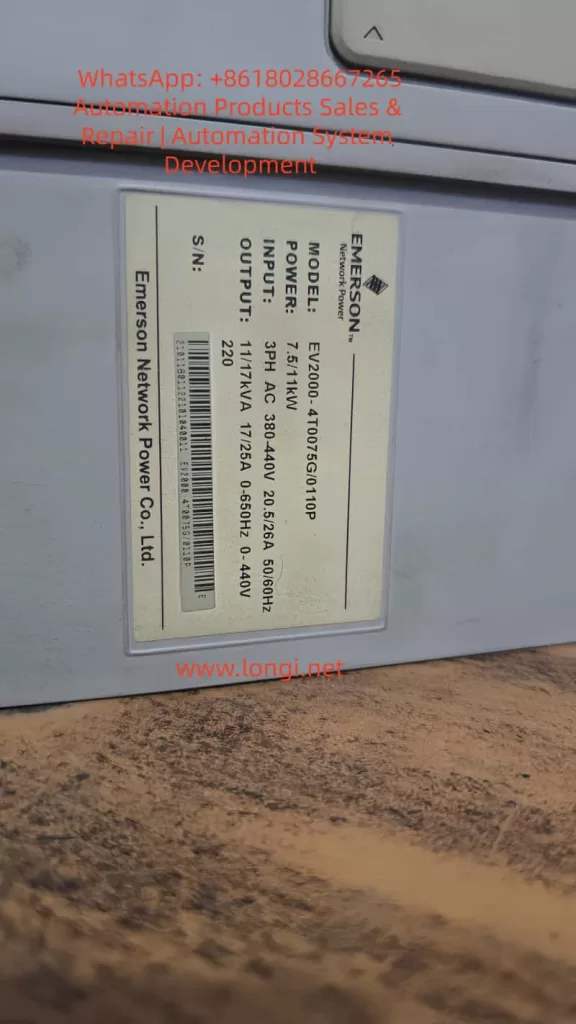
In industrial automation systems, frequency inverters are the key components for controlling motor speed and torque. The operational stability of an inverter directly determines the reliability of an entire production line. Among numerous industrial drive products, the Emerson EV2000 series is well recognized for its robust performance, precise vector control, and adaptability to a wide range of applications — from pumps and fans to textile machines and conveyors.
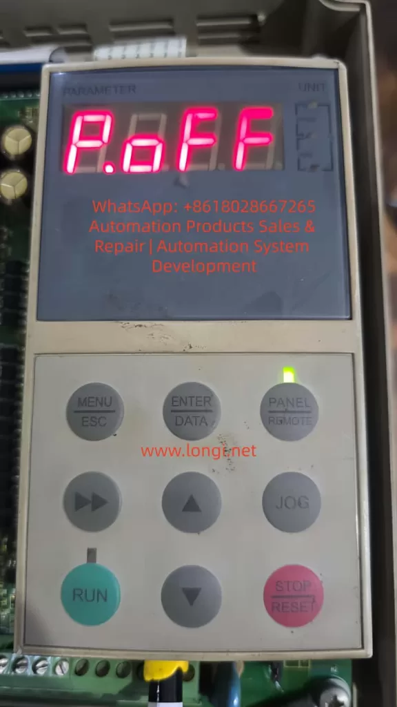
However, during field operation or long-term use, some users may encounter a display message reading “P.oFF” on the inverter’s LED panel.
At first glance, this may look like a severe fault such as a power module failure or control board defect.
In reality, “P.oFF” is not a typical fault alarm, but rather a protective shutdown state known as “Undervoltage Lockout (LU).”
This article provides a comprehensive technical analysis of the P.oFF condition in the Emerson EV2000 inverter.
It integrates official documentation, field diagnostic data, and maintenance experience to explain its causes, triggering mechanism, troubleshooting methods, and preventive measures.
2. Technical Definition of P.oFF
According to the official EV2000 User Manual:
“When the DC bus voltage drops below the undervoltage threshold, the inverter outputs a protection signal and displays ‘P.oFF’ on the LED panel.”
This statement reveals the essence of the fault:
P.oFF occurs when the inverter’s internal DC bus voltage (DC link voltage) falls below a safe limit.
Normally, the rectifier circuit inside the EV2000 converts three-phase AC power (380V ±10%) into DC voltage of approximately 540–620 VDC.
When the input power drops, the rectifier is damaged, the DC bus capacitors age, or the braking unit malfunctions, the DC voltage may fall below the predefined undervoltage threshold (around 300 VDC).
At that point, the inverter automatically enters a protective lockout to prevent unstable operation or component damage.
It is important to note that unlike “E” code faults (such as E001 – overcurrent, E002 – overvoltage), P.oFF does not trigger a trip alarm.
Instead, the inverter temporarily disables output until the voltage returns to normal.
3. Electrical Mechanism Behind the P.oFF State
To fully understand this phenomenon, we must look into the EV2000’s main power structure.
3.1 Composition of the Main Circuit
The inverter’s main power path includes the following key components:
- Input terminals (R, S, T): three-phase AC supply
- Rectifier bridge module: converts AC to DC
- DC bus capacitors: stabilize and filter DC voltage
- Braking unit and resistor: absorb regenerative energy from motor deceleration
- IGBT inverter bridge: converts DC back into PWM-controlled AC output
3.2 How Undervoltage Lockout Is Triggered
The control board constantly monitors the DC bus voltage.
When it detects a voltage lower than the threshold (typically around 300–320 VDC), it executes the following logic sequence:
- Disables IGBT outputs — halting motor operation
- Displays “P.oFF” on the panel
- Waits in standby mode until the DC bus recovers above the normal level (typically >380 VDC)
This mechanism is a preventive protection system designed to shield the inverter from grid voltage sags, capacitor discharges, or transient faults.
Thus, P.oFF is not an error; it is an intentional safety lock.
4. Root Causes of the P.oFF Condition
From field experience and manual analysis, the following are the most common reasons for P.oFF to appear.
(1) Input Power Problems
- Voltage imbalance between the three input phases (>3%)
- Mains voltage below 320V AC or fluctuating severely
- Loose power terminals or poor contact
- Excessive line voltage drop due to long cable runs
These account for nearly half of all P.oFF cases and are primarily related to unstable supply power.
(2) Faulty Rectifier Module
A damaged or open diode inside the rectifier bridge reduces the DC bus voltage, often accompanied by audible hum or irregular current flow.
(3) Aged or Leaky DC Capacitors
Over time, electrolytic capacitors lose capacitance and their internal ESR increases.
This weakens their ability to smooth the DC voltage, resulting in a temporary drop when load or braking energy fluctuates — enough to trigger an undervoltage lock.
In units running for 3–5 years, this is one of the most frequent root causes.
(4) Braking Circuit Malfunction
A shorted braking unit or resistor constantly discharges the DC bus, causing the voltage to collapse.
To verify, disconnect the braking circuit and power on again — if P.oFF disappears, the issue lies in that circuit.
(5) Momentary Power Interruptions
Factories with welding machines, compressors, or heavy inductive loads can experience grid sags.
If the inverter’s “Ride-through” (instantaneous power-loss recovery) function is disabled, any short voltage dip may cause P.oFF.
5. Systematic Troubleshooting Process
To effectively diagnose and repair the P.oFF issue, engineers can follow a step-by-step workflow:
Step 1 – Observe the Symptom
- Panel displays “P.oFF”
- No “E” fault code is present
- Motor stops automatically
- After a few minutes, the inverter may restart on its own
If these conditions match, the inverter is in undervoltage lockout mode.
Step 2 – Measure Input Power
Use a multimeter to measure R–S–T line voltages:
- Normal range: 380–440 V
- Below 360 V or phase difference >10 V → adjust power source or connections
Step 3 – Measure DC Bus Voltage
Check voltage across (+) and (–) terminals:
- Normal: 540–620 VDC
- Below 300 VDC → rectifier or capacitor failure
Step 4 – Isolate the Braking Circuit
Disconnect the braking resistor/unit and test again.
If the problem disappears, replace or repair the braking components.
Step 5 – Test the DC Capacitors
After power-off, measure capacitance and discharge rate:
- If voltage drops to zero within a few seconds, leakage is severe
- Replace if measured capacitance is <70% of rated value
Step 6 – Verify Control Power
Check auxiliary voltages (P24, +10V, +5V).
Low control supply may cause false P.oFF detection.
6. Repair and Recovery Procedures
Once the root cause has been identified, proceed with the following repair actions:
- Stabilize Power Supply
- Re-tighten input terminals
- Ensure voltage balance across all three phases
- Install an AC reactor or voltage stabilizer if necessary
- Replace Faulty Components
- Replace aged electrolytic capacitors as a set
- Replace damaged rectifier modules with same-rated units
- Inspect Braking Circuit
- Measure P–PR resistance for shorts
- Ensure thermal relay contacts (TH1, TH2) are functioning
- Enable Ride-through Function
The EV2000 allows short-duration undervoltage ride-through; enabling this can prevent false P.oFF triggers caused by brief voltage dips. - Recommission and Verify
- Power up and observe DC voltage stability
- Run at light load for 10 minutes, then gradually increase load
- Once the display shows “RDY”, the inverter is ready for normal operation
7. Preventive and Optimization Measures
To avoid recurring undervoltage lockouts, adopt the following best practices:
7.1 Power-Side Protection
- Use proper circuit breakers or fuses rated for inverter service
- Add a DC reactor for harmonic suppression and voltage stabilization
- Use thicker power cables if installation distance is long
7.2 Environmental Control
- Maintain cabinet temperature below 40°C
- Ensure clean airflow; avoid dust, oil, or moisture buildup
- Regularly clean cooling fans and filters
7.3 Periodic Maintenance
- Measure DC bus voltage and capacitor health yearly
- Replace capacitors after ~3 years of continuous operation
- Test rectifier module every 5 years or after heavy load operation
7.4 Parameter Optimization
- Set appropriate acceleration/deceleration times to avoid current spikes
- Enable AVR (Automatic Voltage Regulation) and Current Limit functions
- Review output terminal settings in parameter group F7 to prevent incorrect logic assignments
8. Case Study: Intermittent P.oFF on a 22kW Fan Drive
Background:
A 22kW EV2000 inverter controlling a centrifugal fan exhibited intermittent P.oFF shutdowns after six months of operation.
Symptoms:
- Occurred around 45 Hz operation
- The inverter automatically recovered after a few minutes
- Mains voltage appeared normal
Diagnosis:
- DC bus voltage fluctuated between 520–550V with periodic dips
- Two electrolytic capacitors found bulging and degraded
- Replaced capacitors → inverter operated normally
Conclusion:
The failure was caused by aged capacitors reducing DC storage capacity, resulting in transient undervoltage.
This is a classic “aging-induced P.oFF” scenario.
9. Conclusion
The P.oFF message on Emerson EV2000 inverters is not a random or critical failure, but a designed protective feature to safeguard the drive system when DC bus voltage drops abnormally.
Understanding its mechanism helps engineers correctly differentiate between true hardware faults and temporary protective lockouts.
By following a structured diagnostic approach — from input power verification to capacitor and braking circuit inspection — technicians can quickly restore normal operation.
Furthermore, implementing preventive maintenance and enabling built-in functions such as ride-through and AVR can significantly enhance long-term reliability.
As the design philosophy of Emerson EV2000 suggests:
“Reliability is not accidental — it begins with every small detail of protection.”