
Introduction
In industrial applications, the Vacon NXP series inverters may occasionally experience activation of the Safe Torque Off (STO) function. This causes the drive to stop outputting torque and display warnings such as “A30 SafeTorqueOff” or faults like “F30 SafeTorqueOff”. Usually, this activation is not due to equipment damage but rather a normal response of the safety function, triggered by external input signals, wiring issues, or parameter settings. Based on the Vacon NX OPTAF option board user manual and advanced application manual, this guide provides detailed operational steps to help you diagnose, configure, and bypass (if applicable) the STO function. We will focus on practical steps, including hardware connections, keypad navigation, fault resetting, and test verification. Note: Bypassing the STO function reduces the safety level and should only be used in non-safety-critical applications after conducting a risk assessment. All steps assume you have basic electrical knowledge and safety equipment.
This guide is divided into sections on diagnosis, hardware operations, parameter adjustments, bypass methods, testing, troubleshooting, and maintenance. Each step includes expected keypad displays, key sequences, and handling of potential issues. The goal is to help you quickly resume operations while ensuring compliance.
Step 1: Diagnose the Cause of STO Activation
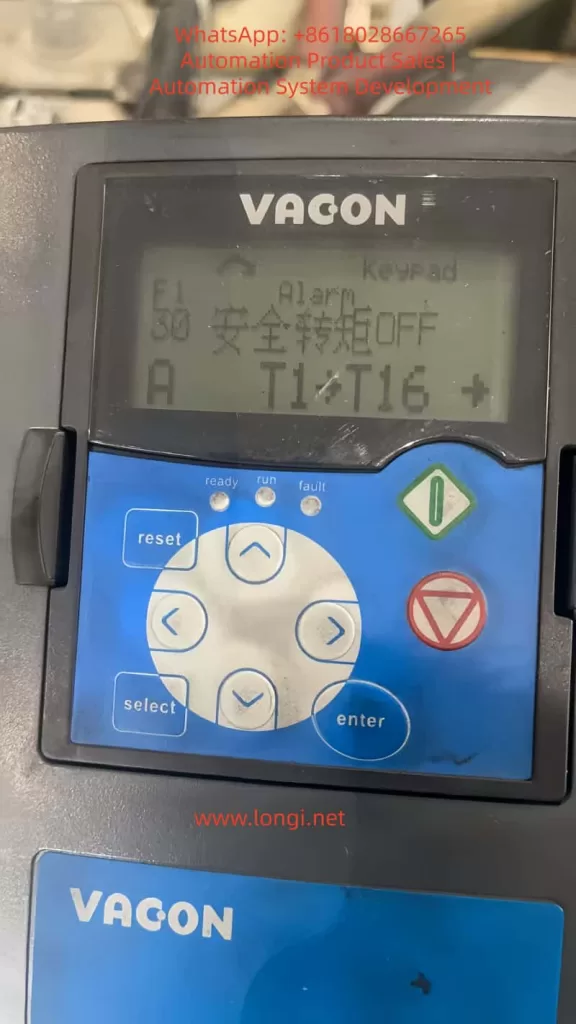
When the STO is activated, the drive’s display will show “F1 Alarm Keypad: 30 SafeTorqueOff” or similar information, accompanied by subcode 30 (indicating that the status of the SD1 and SD2 inputs has been inconsistent for more than 5 seconds). Before starting the diagnosis, ensure that the drive is powered off and locked out to prevent accidental startup.
Sub-step 1.1: Check Monitoring Values to Confirm STO Status
Key Sequence:
- Press Up (↑) or Down (↓) to scroll to the main menu M1 (Monitoring values), displaying: “READY Monitoring M1”.
- Press Menu Right (→) to enter, then scroll to M1.23 (Monitoring values 2) or M1.24 (FieldBus Monitoring), displaying: “READY Monitoring values 2 M1.23”.
- Enter and scroll to view DigIN:B.2 (SD1 status) and DigIN:B.3 (SD2 status). Normally, both should be 1 (closed). If they are different or 0, the STO is activated.
Expected Display: If DigIN:B.2 = 0 and DigIN:B.3 = 1, it shows “S30 STO inputs different state”.
Common Causes: - External safety switches (such as emergency stop buttons) are open.
- Cables are disconnected, short-circuited, or subject to interference.
- The OPTAF board is not installed or is faulty.
Initial Fix: If the status is inconsistent, press the Reset button to reset. If the issue persists, proceed to hardware inspection.
Sub-step 1.2: View Fault History
Key Sequence:
- Scroll to M4 (Fault history), displaying: “READY Fault history M4”.
- Press Menu Right (→) to enter, then scroll to view the most recent faults, such as “F30 SafeTorqueOff Subcode 30”.
- Record the time and subcode for subsequent analysis.
Expected Display: “READY F30 SafeTorqueOff 30”.
Handling: If it occurs repeatedly, check whether the external circuit is sending test pulses (dark/light test pulses). The OPTAF board supports filtering of dark pulses less than 3 ms and light pulses less than 1 ms; pulses exceeding these durations will trigger the STO.
Through these steps, you can confirm that the issue is STO-related rather than other faults such as over-temperature or overload.
Step 2: Hardware Inspection and Wiring Operations
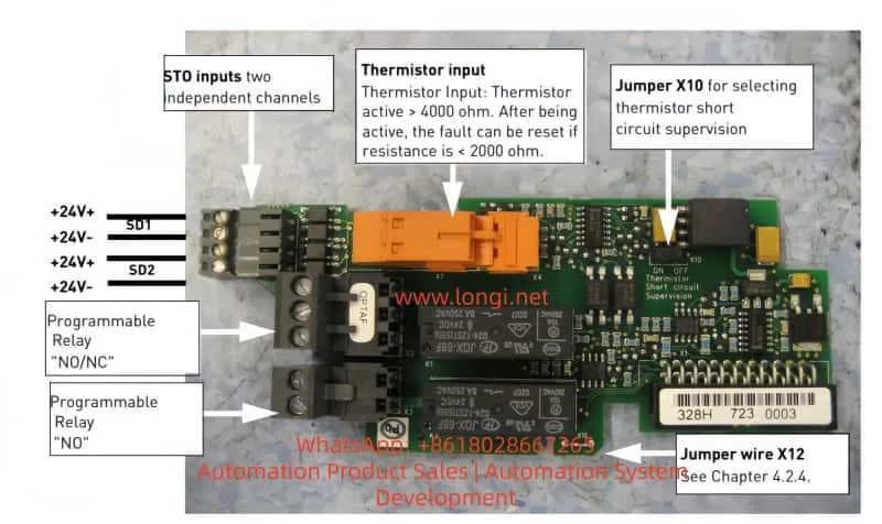
The STO function relies on the OPTAF board (installed in slot B of the control board). Its X2 connector has four terminals: 1 (SD1+), 2 (SD1-), 3 (SD2+), and 4 (SD2-). These are isolated inputs that require a +24 V logic signal.
Sub-step 2.1: Verify OPTAF Board Installation
Steps:
- Power off the drive, open the enclosure, and check whether the OPTAF board (labeled VB00761B or a higher version) is installed in slot B.
- On the keypad: Scroll to M7 (Expander boards), enter Slot B, displaying: “READY OPT-AF Recognized” (if not recognized, reinstall the board).
Issue Handling: If not recognized, clean the contacts and restart the drive. If the fault code S47 (old control board) appears, replace the control board with VB00761B or a higher version.
Sub-step 2.2: Check and Connect STO Inputs
Recommended Cables: Use shielded twisted-pair cables (2x2x0.75 mm²) with a maximum length of 200 m (shielded) or 30 m (unshielded). Ground the shield to reduce interference.
Wiring Example 1: Basic Non-reset Configuration (for simple STO)
- Connect the safety switch S1: Connect terminals 1 and 3 to one end of the normally closed contacts of S1, and terminals 2 and 4 to the other end. Connect the other side to +24 V (from OPT-A1 terminal 6) and GND (terminal 7).
- Normally, when S1 is closed, it provides +24 V to SD1+ and SD2+. When opened, it triggers the STO.
Expected: When the drive is ready, monitor DigIN:B.2 and B.3, which should be 1.
Wiring Example 2: Configuration with Reset - Add a reset button (momentary switch) connected to a digital input (e.g., OPT-A1 terminal 8).
- Parameterize the reset as edge-sensitive: Scroll to G2.2 (Input signals), enter P2.2.1 (Start/Stop logic), and set the reset input.
Wiring Example 3: Configuration with External Safety Relay - Use a time-delay relay (e.g., Pilz PNOZ): Connect the relay output to the STO inputs and the digital output to the drive’s DI (for ramp stopping).
- Connect the relay input to the emergency button.
Issue Handling: Use a multimeter to check for continuity: There should be no short circuit between SD1+ and SD2+. Reverse polarity will not trigger the STO, but test pulses may cause false activation.
Sub-step 2.3: Thermistor Integration (if applicable)
If using the ATEX function, ensure that jumper X12 on the OPTAF board is disconnected; otherwise, it may trigger F48 (parameter mismatch).
Connect TI1+ (28) and TI1- (29) to the PTC sensor (Rtrip > 4 kΩ triggers).
After completing the wiring, restart the drive and press Reset to clear any remaining faults.
Step 3: Parameter Configuration Steps
The STO response is controlled by P2.12.1.6 (ID755, Safe Disable Response), with a default value of 1 (Warning). Changing it to 0 (No response) can suppress the display, but the STO will still stop the output.
Sub-step 3.1: Navigate to P2.12.1.6
Key Sequence (assuming Advanced Application software):
- From the main menu, scroll to M2 (Parameters), displaying: “READY Parameters M2 G1→G12”.
- Press Menu Right (→) to enter, then scroll to G2.12 (Protections), displaying: “READY Protections G2.12”.
- Enter, then scroll to P2.12.1 (Common settings), displaying: “READY Common settings P2.12.1”.
- Enter the parameter list and scroll to P2.12.1.6 (Safe Torque Off mode), displaying: “READY Safe Disable Resp. 1”.
- Press Menu Right (→) to edit, the value flashes; use Up/Down to change it to 0 (No response), and press Enter to save.
Expected Display Change: From “1 (Warning)” to “0 (No response)”.
Lock Handling: If it shows “Locked”, press Stop to stop the drive and try again.
Sub-step 3.2: Configure Restart Behavior (P7.2.1.2)
Navigation: In M7 Expander boards → Slot B → Parameters, scroll to P7.2.1.2 (Start-Up Prev), with a default value of “Fault”.
Setting Steps:
- Change it to “Warning”: Allows automatic recovery after STO if the input is closed.
- Save and verify: Activate the STO and check whether it displays “A26 Start-Up Prev” instead of a fault.
Other Parameters: - If using SS1, set P2.3.1.2 (Deceleration time) in G2.3 (Ramp Control) to be greater than the relay delay (at least 20 ms).
- In G2.2.4 (Digital inputs), assign a DI to the reset (e.g., P2.2.4.1 = Reset).
After changing the parameters, reset the drive for testing.
Step 4: Bypass the STO Function (if not in use)
If the application does not require the STO function, hardware bypass is necessary; parameter changes alone are not sufficient to disable it.
Sub-step 4.1: Hardware Jumper
Steps:
- Power off the drive and open the enclosure.
- Connect terminal 1 (SD1+) and terminal 3 (SD2+) to +24 V (OPT-A1 terminal 6).
- Connect terminal 2 (SD1-) and terminal 4 (SD2-) to GND (OPT-A1 terminal 7).
Warning: This disables the safety function; ensure there is no risk of unintended movement. Use shielded cables to avoid interference.
Verification: After restarting, monitor DigIN:B.2 and B.3, which should remain at 1; no STO display should appear.
Sub-step 4.2: Software-assisted Bypass
Set P2.12.1.6 to 0 to avoid any notifications.
If ATEX is enabled, ensure that the thermistor jumper X12 is correctly set (disconnected if in use).
After bypassing, conduct a complete system test.
Step 5: Test and Verify STO Function
Testing is essential to ensure proper functionality.
Sub-step 5.1: STO Activation Test
Steps:
- Run the motor (press Start).
- Open the safety switch S1; the motor should stop immediately (<20 ms), displaying A30 or F30.
- Check the response time: Use an oscilloscope to monitor the output.
Expected: The motor should coast to a stop with no torque.
Sub-step 5.2: SS1 Test (if configured)
Steps:
- Set the relay delay (e.g., 1 second).
- Activate the stop; the motor should ramp down and then the STO should activate.
- Verify that the delay is greater than the deceleration time.
Expected: The STO status should only be displayed after the delay.
Sub-step 5.3: Fault Recovery Test
Close the input and press Reset; the motor should be restartable (edge-sensitive).
If P7.2.1.2 is set to “Fault”, a new start command is required.
Test Checklist: Risk assessment, cable inspection, reset edge sensitivity, and the risk of runaway for permanent magnet motors.
Step 6: Common Fault Codes and Solutions
Based on the manual, common STO-related faults are as follows:
Sub-step 6.1: F30/A30 SafeTorqueOff (Subcode 30)
Cause: Inconsistent input status for more than 5 seconds.
Solution:
- Check the wiring continuity.
- Replace the cable or switch.
- If it is a test pulse issue, adjust the pulse duration of the safety equipment (<3 ms for dark pulses).
Sub-step 6.2: F8 System Fault (Subcodes 37-40)
Cause: Single hardware issue with the STO inputs.
Solution: Replace the OPTAF board or the control board.
Sub-step 6.3: F8 System Fault (Subcodes 41-43)
Cause: Thermistor input issue.
Solution: Check the resistance of the PTC sensor (<2 kΩ to reset); replace the board.
Sub-step 6.4: F8 System Fault (Subcodes 44-46)
Cause: Mixed issues with STO or thermistors.
Solution: Diagnose the board hardware; contact Danfoss support.
Sub-step 6.5: F26/A26 Start-Up Prev
Cause: A start command is active after STO.
Solution: Set P7.2.1.2 to “No action”; use edge start.
For all faults: Record logs and check after powering off before resetting.
Step 7: Maintenance and Best Practices
Sub-step 7.1: Regular Maintenance
- Check the wiring integrity, grounding, and shielding monthly.
- Test the STO annually: Activate it and verify that the response time is less than 20 ms.
- Monitoring values: Regularly view DigIN:B.2/B.3 and RO outputs (if parameterized).
Sub-step 7.2: Best Practices
- Always conduct a risk assessment; the STO is SIL3-rated, but overall system compliance is required.
- Use edge reset to avoid cyclic faults.
- If the environment is harsh, ensure an IP54 enclosure.
- Record all changes; back up parameters (via NCDrive).
- If the issue is complex, contact our support.
Sub-step 7.3: Advanced Integration
- Integration with PLC: Monitor the STO status through the fieldbus.
- SS1 configuration: Ensure that the deceleration time is greater than the relay delay + 20 ms.
- Maintenance log example: Date, test results, and parameter values.
Conclusion
Through these detailed steps, you can effectively handle STO issues with the Vacon NXP, from diagnosis to configuration and maintenance. Remember, safety comes first; any modifications must comply with regulations.