Posted on

Toshiba VF-PS1 Inverter Stuck at “ELL0” with All LEDs Lit – Root Causes and Solutions

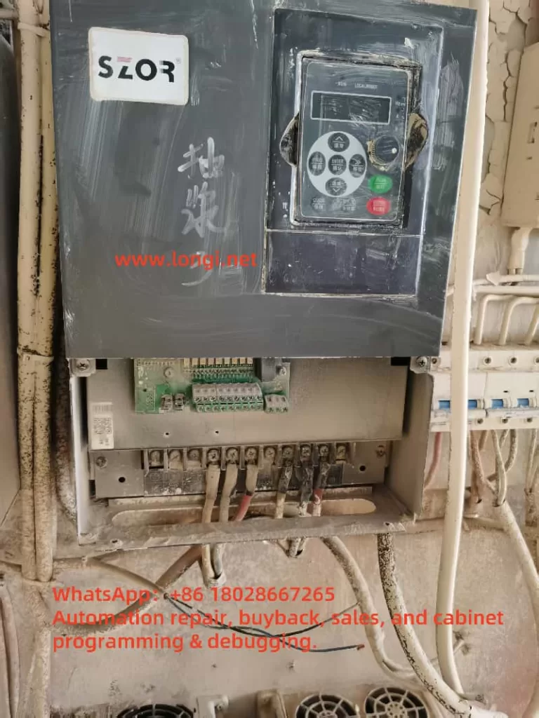
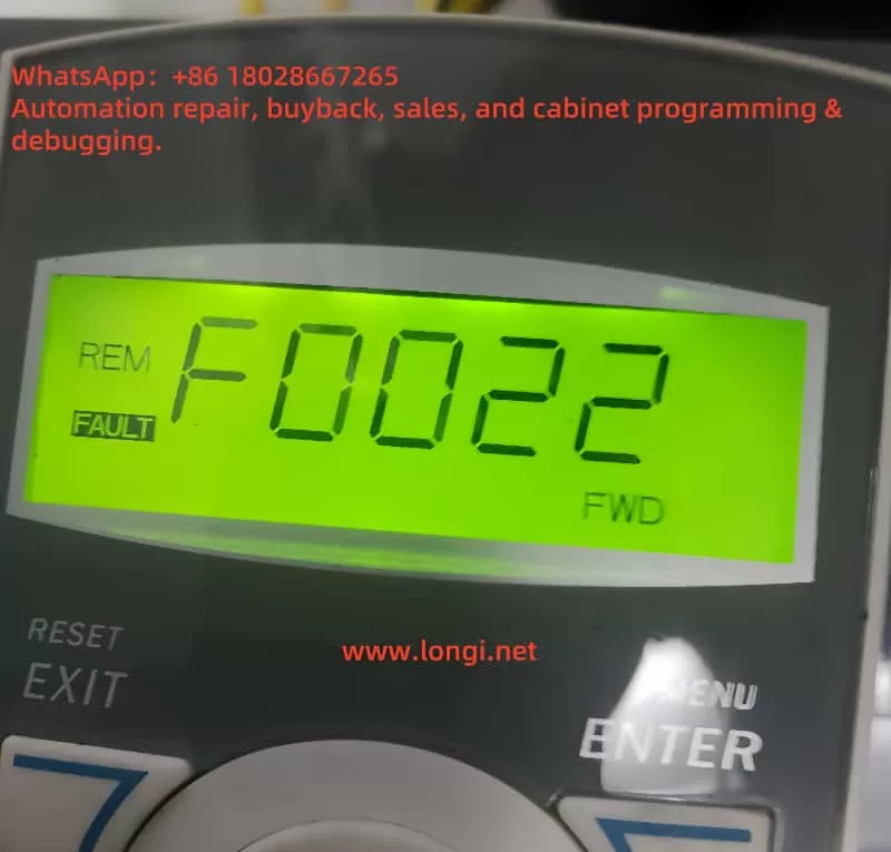
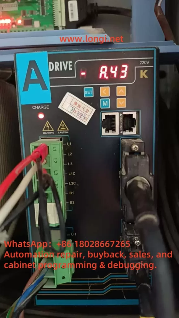
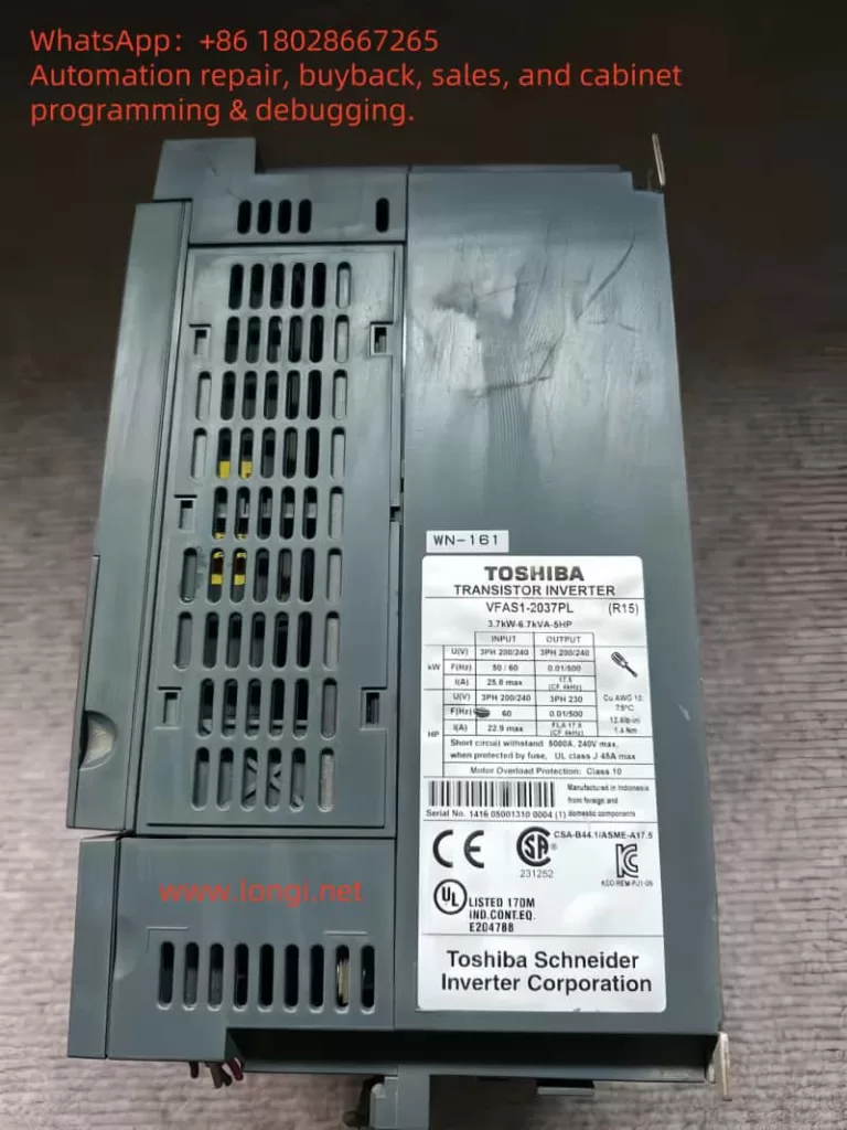
In the field of industrial automation, inverters play a crucial role in driving motors and optimizing energy efficiency. The Toshiba VF-PS1 series is known for its reliability and versatility across a wide range of applications such as manufacturing, HVAC systems, and water treatment. However, during a recent on-site startup, an unusual issue occurred: the inverter powered up and the screen continuously displayed “ELL0”, while all indicator LEDs on the operation panel (RUN, Hz, %, MODE, EASY, etc.) were fully lit and unresponsive. The device failed to transition to its normal frequency display or any operational mode.

ELL0

This article analyzes this abnormal behavior in depth, including its possible causes, technical diagnostics, and step-by-step troubleshooting solutions based on real-world experience. It aims to provide valuable insight for field engineers and maintenance professionals dealing with Toshiba VF-PS1 inverters.


1. Interpreting the “ELL0” Message

The first observation is that the code “ELL0” is not listed in the VF-PS1 manual’s error or alarm code tables. Most standard error codes for Toshiba inverters follow formats like E-xx (e.g., E-10 for analog input error, E-11 for sequence error) or Errx (e.g., Err4 for CPU fault).

Given this, “ELL0” is not a known error code but likely a simplified or stylized display of a word. Considering the limitations of seven-segment or basic LCD panels, the letter “H” may be rendered as “E”, resulting in the word “HELLO” being shown as “ELL0.”

In fact, several other Toshiba inverter series such as VF-S15 are documented to display “HELLO” during startup as a friendly greeting. While VF-PS1 manuals do not explicitly mention this, it is highly plausible that “ELL0” is simply the inverter saying “HELLO” at startup.

Conclusion: “ELL0” is not an error, but a startup message indicating the inverter is initializing.

However, this message is only meant to appear for a few seconds. If the inverter remains stuck on this screen for an extended time, and the display does not change to frequency output, “STOP,” or any other active status, then the system is failing to complete its initialization sequence.


2. Why Are All the LEDs Constantly Lit?

Electronic devices often illuminate all LEDs during the power-on self-test (POST) to confirm the panel is functional. The VF-PS1 has multiple LEDs on its keypad including RUN, Hz, %, MODE, and EASY.

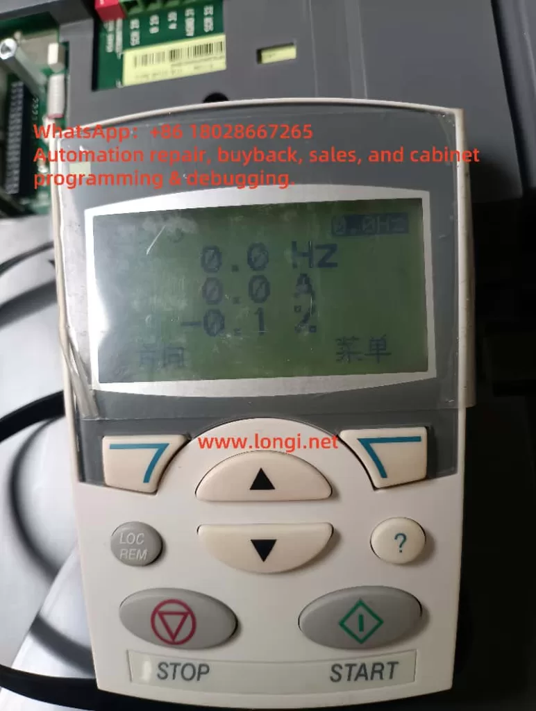
In a normal power-up, these LEDs briefly flash and then only relevant indicators remain lit based on status:

  • In standby: only Hz and power indicators
  • In run mode: RUN LED is lit
  • During fault: alarm LED or fault code appears

⚠️ If all LEDs remain lit indefinitely, this suggests the system has not successfully exited the boot process. When combined with a stuck “ELL0” display, it is a clear sign the inverter is failing to transition to operational state.


VFAS1

3. Possible Technical Causes of the Fault

After analyzing the inverter’s architecture and behavior, the following are the most probable causes for this issue:

1. Main Control Board (CPU) Failure

The control board houses the CPU, EEPROM, and firmware that drive the entire system. If any of these components fail (e.g., due to static discharge, aging, memory corruption), the inverter may not proceed past startup, effectively freezing on the “HELLO” message.

2. Internal Control Power Supply Instability

Toshiba inverters typically generate low-voltage DC internally (e.g., 5V or 24V) to power logic and display. If these voltages are unstable due to aged capacitors or faulty switching circuits, the system may repeatedly attempt to initialize and fail each time.

3. Operator Panel Communication Failure

The panel communicates with the inverter’s main board through a connector or internal bus. If this link is disrupted—due to loose cables, damaged connectors, or panel PCB faults—the display might not receive valid data and remain stuck at its default state.

4. External Expansion Modules Interfering

If optional communication or I/O modules (e.g., Profibus, DeviceNet, or analog expansion) are connected and one of them malfunctions, it may prevent the system from passing its full self-test. This can effectively freeze the inverter before entering active status.

5. Corrupt Parameters or Firmware

Sudden power loss during write operations or faulty parameter resets may corrupt memory. If the inverter firmware or configuration table cannot initialize correctly, the inverter may hang during startup without even reporting an error.


4. Troubleshooting Steps and Solutions

The following field-tested steps may help restore the inverter to normal operation:

Step 1: Perform a Full Power Reset

  • Power off the inverter completely
  • Wait at least 15 minutes to allow internal capacitors to discharge
  • Re-energize and observe whether the display changes from “ELL0” to frequency display or run status

Step 2: Inspect the Panel Connection

  • If the keypad is external, check cable integrity and re-seat connections
  • If it’s an internal panel, check the physical contact to the main board
  • A faulty keypad may need replacement

Step 3: Remove Optional Modules

  • Disconnect any communication modules, expansion I/O boards, or external terminals
  • Reboot the inverter in minimal configuration
  • If the device initializes successfully, one of the peripherals is likely faulty

Step 4: Check Power Input and Control Voltage

  • Measure voltage at R/S/T terminals; confirm it’s within rated range and phase-balanced
  • If possible, measure internal low-voltage DC power (e.g., 5V or 24V) on the control board to ensure stability

Step 5: Attempt Parameter Initialization (if possible)

  • If the panel becomes responsive after reboot, consider resetting parameters to factory defaults
  • This may clear out any corrupt settings

Step 6: Consider Control Board Replacement

  • If none of the above steps restore operation, it’s likely the control board is faulty
  • Repair or replacement of the control PCB is required
  • Only qualified technicians should attempt internal board-level diagnostics

5. Preventive Measures

To avoid similar issues in the future:

  • Avoid frequent rapid power cycling, which can corrupt firmware or cause startup errors
  • Use surge protection and voltage stabilizers to ensure clean input power
  • Periodically inspect cooling fans and capacitors, which degrade over time
  • Only perform parameter resets under safe, powered-down conditions

6. Final Thoughts

While the appearance of “ELL0” on a Toshiba VF-PS1 inverter display might seem alarming at first, it is not inherently a fault code, but rather a welcome message (“HELLO”) that appears during power-up.

However, if the inverter remains stuck on “ELL0” and all panel LEDs stay on, it indicates a serious problem—typically that the inverter failed to complete its startup self-test. Common causes include CPU failure, unstable internal power, communication breakdown with the panel, or peripheral errors.

Technicians are advised to follow a structured troubleshooting process, starting with simple checks and escalating to control board diagnostics if necessary. If the issue persists and the inverter cannot be brought into operational state, professional service intervention or control board replacement is the likely solution.


Posted on

Detailed steps for configuring the MT500 frequency inverter to “display the actual rotational speed in RPM”:

Goal: make the MT 500 drive’s LED keypad show actual motor speed in r/min (RPM).
Assumptions: drive is stopped, control source = keypad.

1 . Enter the parameter list (“Standard menu”)

ActionExpected displayComment
Press ESC repeatedly from the normal monitor screen‑bSC‑“Basic / Standard menu” root 
Press ENTERP00.00You are now at the parameter index level

Tip: ESC moves up one level; ENTER confirms / goes down.


MT500

2 . Fill in the motor name‑plate data

(needed so the drive can translate Hz → RPM correctly)

2‑a  Locate P11.05 Rated frequency
  1. While P00.00 is shown:
    • Press SHIFT until the left‑most digit blinks.
    • Tap UP until that digit becomes 1 → display reads P10.00.
    • Press SHIFT once to move the cursor to the last digit; UP once → P11.00.
    • Tap UP five more times → P11.05.
  2. Press ENTER – the current value (e.g. 50.00) blinks.
2‑b  Edit the value
  • Use SHIFT to select the digit; UP / DOWN to change it.
  • Press ENTER to save. Display flashes End, then returns to P11.05
2‑c  Repeat for P11.06 Rated speed
  • Navigate to P11.06 the same way; enter the motor’s rated RPM; ENTER to save. 

3 . (Optional) Run auto‑tune P11.10

ActionDisplay
Go to P11.10, ENTERvalue blinks (default 0)
UP1 (stand‑still tune) or 2 (rotating tune)
ENTER to store → EndAuto‑tune will start the first time you press RUN afterwards 

4 . Switch the display unit from Hz to RPM — P21.17

ActionExpected display
Press ESC twice to get back to P00.00; jump to P21.17P21.17
ENTER – value blinks (0 = Hz)
UP once → 1 (= RPM)
ENTER to save → EndThe Hz and A LEDs now light together, meaning the keypad shows RPM 

5 . See the live speed

  1. Press ESC until the normal monitor screen returns.
  2. The default monitored variable is r27.00. Because P21.17 = 1, its value is already in RPM. 
  3. Press SHIFT (>>) to step through other view pages if needed; the Hz + A LEDs confirm the unit remains RPM.

mt500-7r5-t4b

6 . (Optional) Show only speed on the monitor page

If you dislike the rotating multi‑page display:

  1. Navigate to P21.11 (run‑mode sequence) and set it to 0001.
  2. Do the same for P21.12 (stop‑mode sequence) if desired.

Now the keypad will lock onto a single page that shows r27.00 in RPM.


Quick trouble‑shooting

SymptomLikely causeFix
Still shows HzP21.17 not saved, or you are viewing another variableRe‑enter 1; check Hz+A LEDs
RPM reading off by a lotWrong name‑plate data or no auto‑tuneRe‑check P11.05 / P11.06, run P11.10
Cannot enter parametersUser lock activeEnter password in P00.00 or restore defaults

Ultra‑short recap

  1. ESC‑bSC‑ENTER → parameter list.
  2. Set P11.05 (rated Hz) & P11.06 (rated rpm).
  3. (Option) P11.10 = 1 or 2, auto‑tune after RUN.
  4. P21.17 = 1 → units = RPM.
  5. Monitor page now shows real speed; enjoy!
Posted on

Troubleshooting Guide for OH Faults in GTAKE GK820 Series Inverter

In the field of industrial automation, frequency inverters play a critical role in motor control. The stable operation of these devices is vital to maintaining production efficiency. The GTAKE GK820 series inverter, known for its performance and reliability, is widely used in various mechanical equipment. However, during operation, users may encounter OH-series fault codes (such as OH1, OH2, OH3), which indicate issues related to overheating protection. Understanding the causes and countermeasures for these faults is essential for maintenance and troubleshooting.

1. Overview of OH Fault Codes

OH1

The OH-series fault codes on the GK820 inverter signify temperature-related issues that trigger automatic protection mechanisms. The main OH faults include:

  • OH1: Heatsink Overtemperature
  • OH2: External Thermal Protection Input
  • OH3: Internal Module Overtemperature

When these faults occur, the inverter halts operation to prevent damage to internal components.

2. Root Causes of Each OH Fault

OH1: Heatsink Overtemperature

The heatsink is critical for dissipating the internal heat generated during inverter operation. When its temperature exceeds a safe threshold, the OH1 fault is triggered.

Possible Causes:

  • High ambient temperature
  • Dust accumulation or blocked airflow on the heatsink
  • Fan failure or insufficient air volume
  • Poor ventilation around the inverter

OH2: External Thermal Protection Input

OH2 faults are generally triggered by external thermal sensors (e.g., motor PTCs) connected to the inverter’s input terminal.

Possible Causes:

  • High ambient temperature
  • Incorrect thermal protection point setting
  • Faulty or broken temperature detection circuit
  • Poor contact or loose connection on the temperature sensor

OH3: Internal Module Overtemperature

OH3 indicates that the inverter’s internal components have exceeded their rated operating temperature.

Possible Causes:

  • Internal fan malfunction
  • Blocked internal air ducts
  • Faulty internal circuit board
  • Long-term overload operation without proper cooling
  • Internal temperature detection circuit failure

3. Troubleshooting and Solutions

Resolving OH1 Fault:

  • Check ambient temperature: Ensure the installation environment is below 40°C.
  • Clean the heatsink: Remove dust and debris regularly to maintain airflow.
  • Inspect the cooling fan: Verify that the fan is working properly; replace it if necessary.
  • Improve ventilation: Leave enough space around the inverter for air circulation and avoid proximity to heat sources.

Resolving OH2 Fault:

  • Check motor thermal sensor (PTC): Ensure correct type and proper installation.
  • Verify parameter settings: Set the correct motor overheat protection threshold.
  • Inspect signal wiring: Ensure the sensor wiring is securely connected and undamaged.
  • Use shielded cable: Reduce electrical interference on sensor signals.

Resolving OH3 Fault:

  • Inspect internal fans: Confirm proper operation and replace faulty fans.
  • Clean internal components: Remove dust that may be affecting internal heat dissipation.
  • Check module temperature detection circuit: Use a multimeter or diagnostic tool to verify if the circuit is working.
  • Avoid overload operation: Reduce long-term full-load usage; apply load margins.
  • Seek service: If the fault persists after inspection, contact GTAKE technical support.

4. Preventive Measures

  • Routine cleaning: Clean air filters, fans, and heatsinks regularly to prevent dust accumulation.
  • Ambient monitoring: Use sensors to monitor room temperature and humidity.
  • Schedule maintenance: Periodically inspect terminal blocks, connectors, and sensors.
  • Avoid overloading: Size the inverter and load correctly; prevent continuous operation at high torque.
  • Install in suitable environments: Avoid corrosive gases, high humidity, or poor ventilation.
GK820M

5. Summary

The OH fault codes in the GK820 series are designed to protect the inverter from damage caused by overheating. By identifying the specific fault (OH1, OH2, or OH3), users can systematically diagnose the root cause and take appropriate corrective actions. Preventive maintenance and environmental management are key to avoiding these issues.

Proper installation, regular inspection, and adherence to usage guidelines will significantly reduce the occurrence of thermal faults and extend the service life of the inverter. If problems cannot be resolved on-site, contacting professional technical support is recommended.

Posted on

User Guide to the SZOR Shenzhen Delta Inverter TD9000 Series Manual

The TD9000 series inverter, developed by SZOR Shenzhen Delta, is a high-performance, highly stable general-purpose drive. It is widely used in applications such as fans, pumps, conveyors, and machine tools. This article introduces the key functions of the TD9000 inverter, including the control panel, password settings, parameter restrictions, parameter initialization, terminal control wiring, potentiometer speed adjustment, and fault diagnostics. It aims to help users operate and maintain the TD9000 series more efficiently and safely.


SZOR INVERTER

1. Control Panel Functions

The TD9000 inverter features an LED digital display and keypad panel. Key functions include:

  • RUN: Starts the inverter.
  • STOP/RESET: Stops operation or resets a fault.
  • PROG: Enters or exits the parameter menu.
  • DATA/ENTER: Confirms parameter modifications.
  • ▲/▼: Scrolls through parameters or adjusts values.

The panel displays parameter codes, output frequency, current, voltage, and other running data. It also supports copy functions to clone parameters from one drive to another, making batch configuration fast and convenient.


2. Password Setup and Parameter Access Restrictions

To prevent unauthorized changes, the TD9000 offers password protection and access-level control.

1. Set Password

  • Parameter P00.08:
    • Set to 0000: No password protection.
    • Set to a 4-digit code (e.g., 1234): Enables password protection.

2. Remove Password

  • If the password is forgotten, hold down special key combinations (e.g., PROG + STOP) during power-up or access maintenance mode to reset it (should be done by qualified personnel).

3. Parameter Access Restriction

  • P00.07: Limits access to basic parameter groups only.
  • P00.12 = 1: Activates user-access mode to restrict changes to key parameters.

3. Restoring Factory Settings

To initialize all parameters:

  • Set P00.13 = 1 to restore factory defaults. The inverter will reboot automatically. Use with caution, as all settings will be erased.

4. Terminal Forward/Reverse Control & External Potentiometer Speed Adjustment

The TD9000 supports terminal-based control and analog input via external potentiometers.

1. Forward/Reverse Terminal Wiring

  • Terminals:
    • S1: Forward run command (default).
    • S2: Reverse run command (customizable).
    • COM: Common ground.
  • Parameter Settings:
    • F00.06 = 2 (terminal control mode).
    • F10.00 = 1 (S1 = Forward).
    • F10.01 = 2 (S2 = Reverse).

Closing the respective terminal switch triggers forward or reverse operation.

2. Potentiometer Speed Control Wiring

  • Wiring:
    • 10V: Power supply to potentiometer.
    • AI1: Signal input from potentiometer center tap.
    • GND: Ground.
  • Parameters:
    • F00.05 = 1 (set AI1 as frequency reference).
    • Fine-tuning via F11.00 ~ F11.02.

Adjusting the potentiometer varies the output frequency for smooth speed control.


TD9000

5. Fault Codes and Troubleshooting

TD9000 has advanced fault diagnostics. Faults are displayed as “ErrXX” codes on the panel.

CodeMeaningCausesSolution
Err01OvercurrentShort circuit, too short accel timeCheck wiring, increase accel time
Err02OvervoltageGrid surge, braking circuit issuesInstall brake resistor, adjust voltage
Err04OverloadHeavy load, frequent starts/stopsReduce load, optimize control sequence
Err05OverheatFan failure, high ambient tempClean fan, improve ventilation
Err08Communication errorPoor RS485 wiring or parameter mismatchCheck communication settings and wiring
Err09Input phase lossMissing phase, grid imbalanceCheck power input and phase integrity
Err10Output phase lossBroken cable or terminal looseInspect output wiring and motor leads

Press STOP/RESET or cycle power to clear most transient faults. If faults persist, consult service engineers.


6. Conclusion and Best Practices

The TD9000 inverter series is versatile and user-friendly. Key suggestions for optimal use:

  • Backup parameters regularly.
  • Assign user-level passwords.
  • Ensure proper cooling and dust-free environment.
  • Follow all safety and wiring instructions in the manual.

By following this guide, users can effectively configure and troubleshoot the TD9000 inverter series for reliable industrial performance.


Posted on

Analysis and Troubleshooting of ABB ACS510 VFD Fault F0022 – Supply Phase Missing

1. Overview of the Fault

In industrial automation systems, the ABB ACS510 series VFD is commonly used to control the speed of 3-phase induction motors such as fans, pumps, and compressors. However, in some startup or operating conditions, users may encounter the following fault message on the control panel:

Display: F0022
Fault Type: SUPPLY PHASE (Phase Missing)

This fault is a protective response by the VFD, indicating an abnormality in the input power supply. According to ABB documentation and field service experience, F0022 means that the ripple voltage on the internal DC bus is too high—usually caused by a missing input phase or a blown input fuse.


F0022

2. Root Cause Analysis of F0022

2.1 Nature of Supply Phase Missing

A 3-phase VFD relies on a stable three-phase AC input (U1-V1-W1) to convert into DC voltage through a rectifier bridge. If any one phase is lost or unbalanced, the resulting DC voltage will exhibit abnormal ripple levels.

⚠️ The ACS510 has internal monitoring circuits that detect high DC ripple voltage and trigger F0022 to protect the drive circuitry.

2.2 Common Causes

  • Blown input fuse on one phase;
  • Loose or oxidized input terminal connections;
  • Wiring errors or damaged input cables;
  • Phase loss due to upstream switchgear failure (e.g., contactors or circuit breakers);
  • Severe voltage imbalance in the power supply;
  • Non-simultaneous tripping of breakers causing a single-phase dropout.

3. Step-by-Step Troubleshooting for F0022

Follow these steps systematically to identify and fix the F0022 fault:

Step 1: Check for Actual Phase Loss

Use a multimeter or phase sequence meter to measure voltage between U1-V1-W1 on the drive input:

  • All three phase-to-phase voltages should read within rated limits (typically 380V ±10%);
  • Any phase showing zero or very low voltage confirms a missing phase.

Step 2: Inspect Fuses

Open the power distribution panel and:

  • Check if one of the fuses is open/blown;
  • Test with a multimeter for continuity across each fuse;
  • Replace faulty fuses with the correct type and current rating.

Step 3: Check Terminal Connections

  • Ensure the terminal screws at U1/V1/W1 are tight;
  • Remove any oxidized or burned wires and reconnect properly;
  • Verify copper wire strands are not damaged or frayed.

Step 4: Verify Upstream Circuit Breakers or Contactors

  • Inspect whether one contact is worn or not engaging properly;
  • Replace defective contactors or breakers as needed.

Step 5: Check for Voltage Imbalance

  • Even if all phases are present, large voltage differences can trigger F0022;
  • Measure all three phases—any deviation beyond 10% is problematic;
  • If imbalance is observed, investigate upstream transformer or supply source.

ACS510

4. Preventive Measures for F0022

To prevent recurrence of this fault, consider the following strategies:

4.1 Use Proper Fuses and Breakers

  • Use appropriately rated fuses with fast-acting response;
  • Avoid low-quality circuit breakers with uneven trip behavior;
  • All three phases should be protected with identical devices.

4.2 Add Phase Loss Protection Relay

Install a phase monitoring relay before the VFD input to shut down the system if a phase loss or imbalance is detected.

4.3 Perform Routine Terminal Maintenance

  • Periodically check for loose or oxidized connections;
  • Retorque terminal screws according to the drive’s manual;
  • Re-terminate aged or discolored wires.

4.4 Stabilize the Power Supply

  • Use voltage regulators if power quality is poor;
  • For large-scale systems, consider using isolation transformers or UPS systems to ensure voltage stability.

5. Fault Reset and Drive Recovery

After eliminating the cause of the F0022 fault:

  1. Power down the drive and wait at least 5 minutes (for DC bus capacitors to discharge);
  2. Confirm that all input phases are present and balanced;
  3. Power on the drive and check if the fault is cleared;
  4. Press the RESET or STOP key to reset the fault;
  5. Resume normal operation as needed.

6. Conclusion

The F0022 “Supply Phase Missing” error in ABB ACS510 drives is a common input power issue indicating one or more phase anomalies. The built-in protection mechanism helps safeguard the VFD and motor from damage.

By understanding the electrical causes and following a structured diagnostic approach, maintenance personnel can quickly resolve this issue. Regular inspections, proper component selection, and proactive maintenance of power supply infrastructure are key to preventing such faults and ensuring stable long-term operation of the drive system.


Posted on

Analysis and Solutions for the E1.BE Fault in Shihlin SF Series Inverters

1. Background and Fault Phenomenon

At industrial sites, the Shihlin SF series inverters (e.g., SF‑040‑5.5K) display both “E1” and “BE” (or “bE”) codes simultaneously on the screen, as shown in the figure. This indicates that the inverter is currently in an “E1.BE” alarm state, typically accompanied by internal control shutdown, output disconnection, and other protective actions, causing the driven motor to stop running and affecting production continuity.

E1.BE

2. Alarm Code Interpretation

2.1 Definition of “E1” Abnormality

“E1” is the first-level alarm (Latest Alarm) of the inverter, used for general abnormality alarms. It is triggered immediately when an abnormality occurs in any aspect. However, this code does not directly define the cause of the fault but serves as a “trigger alarm” indicator, requiring subsequent additional information to determine the specific fault.

Through parameter group 06‑5606‑61 (e.g., P.752–P.757), the output frequency, current, voltage, temperature rise, PN voltage, and elapsed operating time at the time of the alarm can be read to assist in diagnosis.

2.2 Meaning of “BE” / “bE” Fault

“BE” refers to Brake‑relay abnormality, one of the hardware detection alarms, indicating an abnormality in the brake relay circuit or an out-of-range detection value.

The relevant code comparison also states: “brake resistor abnormal (Abnormal relay).”

Therefore, “E1.BE” indicates that the inverter has simultaneously triggered an E1 alarm and detected an abnormality in the brake unit.

3. Possible Causes of the Fault

Based on the hardware structure and on-site operating characteristics, the causes can be classified into the following categories:

3.1 Brake Relay Body Fault

The brake relay may have poor contact, damaged moving and stationary contacts, a short-circuited/open-circuited relay coil, etc., preventing it from switching states normally or causing abnormal sensing.

3.2 Brake Module and Resistor Abnormality

If the inverter integrates a braking unit (DBU) but the internal braking resistor is damaged, open-circuited, or loosely connected, it will also result in a failed detection of the brake circuit, triggering a BE alarm.

3.3 Loose Wiring or Interface

The brake unit is connected to the inverter mainboard via pins or terminals. If the connection is loose, oxidized, or dirty, it will also result in the inability to detect the expected state.

3.4 External Circuit Interference

Electromagnetic interference or high-voltage power supplies can cause malfunctions in the brake control circuit, including frequent operation of the brake relay or abnormal feedback. The manual recommends adding magnetic rings for filtering on sensitive lines.

4. Diagnostic Process and Response Strategies

4.1 Safety Isolation and On-Site Initial Inspection

  • Power off and shut down the machine, turn off the main power supply, and wait for the DC circuit charge to dissipate (red light goes out).
  • Ensure there is no voltage before opening the front door/removing the panel to avoid electric shock.

4.2 Inspection of Wiring, Plugs, and Interfaces

  • Disassemble the brake module, clean the interface, and use 600# fine sandpaper or contact cleaner to treat the oxide layer.
  • Ensure all connections are tight and reliable, with no increase in impedance.

4.3 Testing of Relay Coil and Moving Contacts

  • Use a multimeter to measure the coil resistance to check for open/short circuits.
  • Power on and test the coil drive to measure whether it engages. If it fails to engage or the contacts do not close, it is damaged.

4.4 Electromagnetic Interference Investigation

  • Check if the brake lines are bundled with high-voltage main circuits or contactor output lines.
  • Install magnetic rings or EMI filters and plan the wiring sequence to avoid mutual interference.

4.5 Replacement of Spare Relays or Components

  • If a relay is suspected to be damaged, contact the manufacturer to purchase compatible replacement parts. If necessary, send the inverter along with the brake unit for repair.

5. On-Site Maintenance Recommendations

5.1 Regular Inspections

The brake relay should be maintained every 3–6 months, including cleaning the coil, contacts, and checking the wiring harness.

5.2 Environmental Considerations

  • Avoid operating the inverter in humid, vibrating, or dusty environments; if necessary, equip the inverter with a protective enclosure and ensure good heat dissipation.

5.3 Parameter Monitoring and Alarm Logging

  • Enable parameter groups P.290, P.291, etc., to collect brake action records through the PU panel or PC, enabling earlier detection of abnormal trends.

5.4 Comprehensive Analysis of E1 Abnormalities

“E1,” as a first-level alarm, can be paired with parameter groups P.752–P.758 to obtain on-site condition data. Combined with the alarm code BE, it generally indicates a hardware problem rather than operational parameter issues such as current overload.

SF-040-5.5K

6. Case Studies

Case 1: Brake Coil Open Circuit

An inverter on-site displayed an E1.BE alarm. Upon disassembly and inspection, it was found that the brake module had been used for an extended period in a hot environment, causing insulation aging and an open circuit in the internal coil. Replacing the relay module restored normal operation.

Case 2: Connector Oxidation

After multiple power-on cycles, the exposed positions of the relay interface oxidized, resulting in poor contact. Cleaning the contacts, applying anti-oxidation oil, and tightening the connections eliminated the fault.

Case 3: Strong Electrical Interference Triggering False Alarms

The brake output lines were frequently routed in parallel with the main power supply, subject to electromagnetic interference. The factory installed magnetic rings for filtering on the brake lines and rerouted them, after which the BE alarm did not recur.

7. Summary and Recommendations

“E1.BE” represents a brake relay hardware abnormality, not an ordinary PID or current overload fault. Handling should focus on hardware, wiring, and electromagnetic environment investigations. Key points are as follows:

  • Ensure safety by powering off before operations.
  • Carefully inspect the relay body and coil.
  • Clean and tighten all relevant wiring and connectors.
  • Strengthen wiring and filtering to prevent EMI.
  • Enable alarm logging and monitoring, and conduct regular inspections.
  • Replace modules or report to the Shihlin manufacturer for repair if necessary.

By following these methods, on-site equipment can quickly resume stable operation, reducing the risk of mis-shutdowns and production interruptions.

8. Final Recommendations

  • Incorporate brake relays and modules into routine maintenance projects.
  • Conduct special inspections of on-site wiring specifications and EMI layout.
  • Recommend configuring spare parts for commonly used modules at key nodes for quick replacement.
  • If BE alarms occur frequently, suspect core hardware aging and directly contact the manufacturer for repair. Do not ignore hardware quality issues.
Posted on

Schneider ATV340 “Load Movement Error” Analysis and Solutions

Introduction

Variable frequency drives (VFDs) are critical components in modern industrial automation systems, widely used in motor control applications to achieve precise speed and torque regulation, enabling efficient production, energy savings, and extended equipment lifespan. Schneider Electric, a globally renowned electrical equipment manufacturer, offers the ATV340 series VFDs, which are known for their superior performance, high reliability, and versatile features. These drives excel in industrial applications requiring high dynamic response and precise control, such as cranes, conveyor systems, and processing machinery.

However, in practical applications, the ATV340 VFD may encounter various faults, one of which is the “Load Movement Error” (fault codes [nLdCF] or [MDCF]). This fault can disrupt production processes, potentially cause equipment damage, or pose safety risks, making timely identification and resolution essential. This document provides a detailed analysis of this fault, covering its definition, causes, diagnostic methods, solutions, and preventive measures to assist users in effectively addressing the issue.


Load movement error

Fault Description

The “Load Movement Error” occurs when the load (i.e., the mechanical component driven by the motor) moves unexpectedly without any motion command. On the ATV340 VFD’s display, this fault is typically indicated as “Load Movement Error” or the code “nLdCF,” and it may also appear as “0050Hex” in hexadecimal format. According to the Schneider ATV340 programming manual, this error indicates that the system has detected abnormal load behavior during a stopped or uncontrolled state.

Fault Symptoms

  • Display Indication: The VFD displays “Load Movement Error” or “nLdCF” and enters a fault protection state.
  • Motor Behavior: The motor may rotate unexpectedly when not commanded, or the load may shift after the motor stops.
  • System Impact: The VFD ceases output, preventing normal motor operation, which may lead to production interruptions.

This fault is particularly critical in applications like cranes or hoists, as unexpected load movement could result in dropped cargo, equipment damage, or safety hazards for on-site personnel.


Fault Cause Analysis

The “Load Movement Error” can stem from various factors. The following are common causes based on the ATV340 programming manual and practical application experience:

1. Brake System Issues

  • Brake Command Circuit Problems: Loose wiring, poor contact, or damaged components in the brake command circuit may prevent proper transmission of brake signals, causing the brake to fail.
  • Brake Failure: Mechanical wear, improper adjustment, or aging of the brake itself may result in insufficient braking force, failing to prevent load movement.

2. Incorrect Parameter Settings

  • Load Movement Detection Parameters: The ATV340 supports load movement detection through parameters [BRH b5] and torque threshold reference [TTR]. If [BRH b5] is not enabled (default is NO) or [TTR] is set inappropriately, it may lead to missed or false detections.
  • Mismatched Motor Control Type: If the parameter [CTT] (motor control type) is not set correctly to [FVC] (standard for asynchronous motors) or [FSY] (standard for synchronous motors), it may cause control instability, leading to abnormal load movement.
  • Insufficient Load Holding Time: If the parameter [MD FT] (load holding time) is set too short, the system may fail to detect load status properly after power restoration, triggering the error.

3. Mechanical System Issues

  • Loose Transmission Components: Loose or damaged couplings, gears, or belts may allow the load to move even when the motor is stopped.
  • Unstable Load Fixation: In hoisting applications, an unstable load center of gravity or faulty securing mechanisms may cause movement due to gravity.

4. Electrical System Issues

  • Unstable Power Supply: Voltage fluctuations or momentary power interruptions may disrupt the VFD’s normal control, leading to load instability.
  • Electromagnetic Interference: Strong electromagnetic interference on-site may affect the VFD’s signal processing, causing erroneous actions.

5. External Factors

  • External Forces: Forces such as wind, gravity, or other external influences acting on the load may cause movement when the motor is stopped.

ATV340

Fault Diagnosis Methods

To accurately identify the cause of the “Load Movement Error,” users can follow these systematic diagnostic steps:

1. Review Fault Information

  • Check Display: Note the fault code (e.g., “nLdCF” or “0050Hex”) and the “Latest Error 1 Status” on the VFD display.
  • Access Fault History: Use programming software or an HMI to review the fault occurrence time and frequency to analyze triggering conditions.

2. Inspect Brake System

  • Brake Command Circuit: Use a multimeter to test the continuity of the circuit wiring and verify the functionality of relays or contactors.
  • Brake Condition: Manually check the brake’s engagement and release to ensure its mechanical performance is intact.

3. Verify Parameter Configuration

  • Load Movement Detection: Access the parameter menu and confirm if [BRH b5] is set to “YES” (enabled). If set to “NO,” the detection function is disabled.
  • Motor Control Type: Ensure the [CTT] parameter matches the motor type ([FVC] for asynchronous motors, [FSY] for synchronous motors).
  • Load Holding Time: Check the [MD FT] setting, which defaults to 1 minute. Adjust it to 1–60 minutes based on application needs.

4. Inspect Mechanical System

  • Transmission Components: Check for looseness or wear in couplings, gears, or other components.
  • Load Fixation: Ensure the load is securely fixed in the stopped state and not subject to external forces.

5. Monitor Electrical Environment

  • Power Quality: Use a voltmeter to monitor input voltage, ensuring it remains within the VFD’s acceptable range (typically 380V ±15%).
  • Electromagnetic Interference: Assess whether strong interference sources, such as high-power equipment or unshielded cables, are present on-site.

6. Observe Load Behavior

  • Under safe conditions, disconnect the motor power and observe whether the load moves due to external forces or mechanical looseness.

Fault Resolution Measures

Based on the identified causes, the following are specific solutions:

1. Repair Brake System

  • Circuit Repair: Replace damaged wiring or components to ensure accurate brake command transmission.
  • Brake Adjustment: Repair or replace the brake to ensure sufficient braking force and timely response.

2. Optimize Parameter Settings

  • Enable Detection Function: Set [BRH b5] to “YES” to activate load movement detection.
  • Adjust Torque Threshold: Configure [TTR] based on load characteristics to ensure appropriate detection sensitivity.
  • Match Control Type: Set [CTT] to [FVC] or [FSY] to align with the motor type.
  • Extend Holding Time: Adjust [MD FT] to an appropriate value (e.g., 5 minutes) to prevent false alarms after power restoration.

3. Strengthen Mechanical System

  • Tighten Components: Secure or replace loose transmission components.
  • Secure Load: Add fixing mechanisms to ensure load stability.

4. Improve Electrical Environment

  • Stabilize Power Supply: Install a voltage regulator or UPS to maintain stable voltage.
  • Reduce Interference: Shield control circuits and optimize equipment layout to minimize electromagnetic interference.

5. Clear Fault Code

  • Reset Operation: After resolving the issue, use the [ATR] (automatic fault reset) or [RSF] (reset fault) parameter to clear the error code. If necessary, reset [MTBF] (load holding delay) by powering off and restarting the device.

Preventive Measures

To reduce the likelihood of “Load Movement Error,” users can implement the following preventive measures:

1. Regular Maintenance

  • Brake System: Inspect the brake and its circuit monthly, replacing worn components promptly.
  • Mechanical System: Regularly tighten transmission components to prevent looseness.

2. Standardized Parameter Management

  • Parameter Backup: Save parameter configurations after commissioning for quick restoration after faults.
  • Periodic Review: Check critical parameters (e.g., [BRH b5], [CTT]) quarterly to ensure correctness.

3. Personnel Training

  • Operational Standards: Train operators on proper VFD usage to avoid errors.
  • Emergency Handling: Teach basic fault diagnosis skills to improve response capabilities.

4. Optimize Operating Environment

  • Power Protection: Ensure a stable power supply to avoid fluctuations.
  • Interference Mitigation: Optimize wiring to reduce electromagnetic interference.

Conclusion

The “Load Movement Error” is a common fault in Schneider ATV340 VFDs, potentially caused by brake system failures, incorrect parameter settings, mechanical looseness, electrical issues, or external forces. Through systematic diagnosis—reviewing fault information, inspecting brake and mechanical systems, and adjusting parameters—users can effectively identify and resolve the issue. Additionally, preventive measures such as regular maintenance, standardized operations, and environmental optimization can significantly reduce fault occurrences, ensuring long-term stable equipment operation.

In industrial automation, promptly and accurately addressing VFD faults is critical to maintaining production efficiency and safety. This document aims to provide practical guidance to help users better understand and manage the ATV340’s “Load Movement Error,” enhancing their confidence and capability in equipment management.


Posted on

Detailed Explanation and Solutions for the Safety Function Error (SAFF) in Schneider ATV630 Inverters

I. Overview

In modern industrial automation control systems, inverters play an extremely crucial role. The ATV630 series inverters launched by Schneider Electric are widely used in fields such as fans, pumps, and compressors, offering energy efficiency, flexible control, and extensive communication capabilities. However, during actual use, users may occasionally encounter a fault message on the screen indicating “Safety Function Error,” often accompanied by a status display of “STO,” indicating that the inverter is in a safe shutdown state.

This article provides a detailed analysis of the meaning of this error, its possible causes, wiring considerations, and practical methods for troubleshooting and resolving the fault.

Safety Function Error

II. Fault Meaning Analysis

On the ATV630 inverter, the “Safety Function Error,” or SAFF (Safety Function Fault), is a type of fault related to the STO (Safe Torque Off) safe shutdown function.

2.1 Overview of STO Function

STO (Safe Torque Off) is a safety function compliant with the IEC 61800-5-2 standard. Its primary role is to quickly disconnect the motor torque by shutting off the power output to the motor without cutting off the main power supply of the inverter.

2.2 Meaning of SAFF Fault

According to Schneider’s official manual, the specific definitions and possible causes of SAFF (safety function error) are as follows:

Possible Causes:

  • Inconsistent states (high/low) of the STOA and STOB inputs for more than 1 second;
  • Debounce time timeout;
  • Internal hardware failure (modules related to safety functions).

Solutions:

  • Check the wiring of the STOA and STOB digital inputs;
  • Verify that jumpers are reliably connected;
  • Contact Schneider’s official technical support if necessary;
  • Clear the fault by performing a power reset.

III. Wiring Principles and Common Error Analysis

The STO function of the ATV630 typically uses terminals “STOA” and “STOB” to receive 24V inputs. Both ports must be at a high level simultaneously for the inverter to operate.

3.1 Standard Wiring Method

STOA ←→ 24VDC

STOB ←→ 24VDC

If the safety function is not used, “STOA” and “STOB” can be connected to “24V” respectively using short jumpers on the terminal block.

For example, in the picture you uploaded, the yellow jumpers connect “STOA→24V” and “STOB→24V,” which is theoretically correct.

3.2 Common Wiring Errors

  • Connecting only one STO port (e.g., only STOA):
    This leads to inconsistent states between the two, triggering the SAFF.
  • Loose or poor contact wiring:
    Loose plugs, oxidation, or insufficient tightening can cause intermittent faults.
  • Incorrect jumper placement or use of non-industrial-grade wires:
    This can result in high-frequency interference or open circuits in the wiring.
STOA STOB

IV. Detailed Troubleshooting and Resolution Steps

Step 1: Check STO Wiring

  • Turn off the power and open the terminal cover;
  • Verify that both STOA and STOB are connected to 24V and ensure reliable connections;
  • If the safety circuit is not used, short-circuit “STOA” and “STOB” using industrial-grade copper wires;
  • Use a multimeter to measure the voltage of STOA and STOB relative to ground to confirm it is around 24V.

Step 2: Observe Parameter Status

From the current control panel screenshot:

  • ETA state word = 0x0050
  • ETI state word = 0x0003
  • Cmd word = 0x0006
  • Drive state = STO

This indicates that the inverter has detected that the STO signal is not satisfied, preventing it from running.

Step 3: Fault Clearance Method

According to the manual, SAFF-type faults must be cleared by power cycling:

  • Disconnect all main and control power supplies;
  • Wait 15 minutes for the DC bus capacitors to fully discharge;
  • Ensure correct wiring before reapplying power;
  • Press the “STOP/RESET” button or use the rP parameter to restart the product;
  • The fault should be cleared. If it persists, consider hardware issues or the use of an external safety circuit mode.

V. Extended Analysis: Is Enhanced Safety Function Enabled?

In certain applications, enhanced safety function modules (such as safety relays, Pilz, Sick, etc.) may be enabled, requiring STOA and STOB to be closed through these certified devices. If you have enabled “safety module enable (e.g., parameters such as SDI, IFSB, etc.),” the following situations may occur:

  • The wiring appears correct, but the inverter’s internal logic judges it as illegal;
  • The safety circuit must be closed within a specific time window; otherwise, a timeout will occur.

Check Parameters
Access the menu via the graphic terminal:
[Full Menu] → [Input/Output Configuration] → [Safety Function Allocation]
Check whether parameters such as “STO Input Allocation” and “Fault Reset Allocation” are controlled by external signals.

VI. Practical Suggestions and Summary

  1. When using default jumpers, ensure:
  • Use a dual-core yellow wire to jump STOA and STOB to 24V;
  • Ensure good contact, no oxidation, and no broken strands;
  • Avoid cross-wiring with other I/Os.
  1. When enabling safety functions, it is recommended to configure:
  • Use external safety modules compliant with PLe/SIL3 levels;
  • Use example wiring diagrams provided by Schneider to avoid logical confusion;
  • Configure digital inputs to monitor the status of the safety circuit (e.g., DI5/DI6 to monitor STO feedback).
  1. Fault clearance sequence:
  • Eliminate the root cause of the fault;
  • Ensure correct wiring;
  • Perform a RESET or power cycle;
  • Check whether “Fault Reset” and “STO Configuration” are activated in the menu.

VII. Conclusion

Although the “Safety Function Error” is a common protection mechanism in the ATV630 series, its underlying principle is to protect equipment and personnel safety. Understanding its working mechanism and control logic is crucial. Proper handling of STO ports and parameter configuration is the basic prerequisite for ensuring the safe operation of the equipment.

Through the systematic explanation in this article, readers should now be able to independently address such issues, quickly locate and accurately resolve them, and avoid situations where equipment cannot operate due to “STO false alarms.”

Posted on

Understanding and Resolving the E-15 Fault Code on the SQ1000 Inverter

Introduction

The SQ1000 series inverter, manufactured by Suqu, is a robust and versatile piece of industrial equipment designed to deliver high torque, precision, and a wide range of speed adjustments for various mechanical applications. Its advanced control technology and adaptability to harsh environmental conditions—such as fluctuating power grids, extreme temperatures, humidity, and dust—make it a popular choice in industrial settings. However, like any sophisticated machinery, it can encounter operational issues, one of which is the E-15 fault code. According to the SQ1000 Series Inverter Detailed Manual, the E-15 code signifies “undervoltage during operation.” This article provides an in-depth exploration of what this fault code means, its potential causes, and a comprehensive guide to troubleshooting and preventing it, based on the user-provided image and manual references.

What is the E-15 Fault Code?

Definition and Significance

The E-15 fault code on the SQU1000 inverter indicates that the device has detected an input voltage below the acceptable threshold while it is actively running. This undervoltage condition triggers a protective mechanism to halt operation, preventing potential damage to the inverter or the connected motor. The manual (page 66) lists E-15 under the fault code table, explicitly associating it with “undervoltage during operation.” The undervoltage protection threshold is typically governed by parameter F8.02, which defines the voltage level below which the inverter will trip. For instance, if F8.02 is set to 160V, the inverter will display E-15 and stop if the input voltage drops below this value during operation.

This fault is significant because it not only interrupts the inverter’s functionality but also signals an underlying issue that could affect the entire system. Ignoring or repeatedly encountering this fault without resolution may lead to reduced equipment lifespan, motor instability, or production downtime.

Insights from the Image

Th image shows an SQ1000 inverter with a power rating of 0.75 kW, configured for single-phase 220V input and three-phase 220V output, with a rated current of 3.8A. The operation panel displays “E-15” on its five-digit LED screen, accompanied by a flashing red display, indicating an active fault state. The “V” indicator light is illuminated, suggesting that the fault pertains to voltage. The panel includes control buttons such as “Shift,” “Function/Program,” “Confirm,” “Up/Down,” and “Stop/Reset,” which are essential for troubleshooting and parameter adjustments. The inverter’s surface shows signs of dust and wear, hinting at operation in a challenging industrial environment, which may contribute to the fault’s occurrence.

Potential Causes of the E-15 Fault

The E-15 fault can stem from various sources, ranging from external power supply issues to internal inverter malfunctions. Based on the manual and practical considerations, the following are the primary causes:

  1. Unstable Input Power Supply
    The manual (page 7) specifies that the SQ1000 inverter operates within an input voltage range of 220V ± 20% (176V–264V for single-phase models) or 380V ± 15% (323V–437V for three-phase models). Voltage fluctuations beyond these limits, common in industrial settings during peak load times, can trigger the E-15 fault.
  2. Power Line Issues
    Excessive line length or undersized wire gauge can cause significant voltage drops. The manual (page 11, Chapter 3: Installation and Wiring) emphasizes the importance of reliable power connections to minimize such drops, recommending that voltage loss remain below 5%.
  3. Insufficient Power Supply Capacity
    If the power transformer or supply source cannot handle the combined load of the inverter and other equipment, the voltage may sag, leading to undervoltage conditions.
  4. Internal Inverter Faults
    A malfunction in the inverter’s power detection circuit or drive board could falsely detect low voltage. The manual (page 67) suggests that persistent fault displays despite normal voltage may indicate drive board or output module issues.
  5. External Electromagnetic Interference
    While the SQU1000 boasts good electromagnetic compatibility (page 3), strong interference from nearby equipment, such as large motor startups, could disrupt voltage sensing, causing erroneous fault triggers.

Troubleshooting the E-15 Fault

Resolving the E-15 fault requires a systematic approach to identify and address the root cause. Below is a step-by-step guide:

Step 1: Verify Input Power Supply

  • Action: Measure the voltage at the inverter’s input terminals (R, S, T) using a multimeter.
  • Expected Range: For the 0.75 kW single-phase model shown in the image, the voltage should be between 176V and 264V.
  • Solution: If the voltage is below 176V, consult the local power utility to address grid instability or install a voltage stabilizer (e.g., UPS) upstream of the inverter.

Step 2: Inspect Power Lines and Connections

  • Action: Check the power cable length, wire gauge, and terminal connections for adequacy and security.
  • Guideline: Ensure the voltage drop across the line is less than 5% of the supply voltage.
  • Solution: Replace undersized or overly long cables with appropriately rated ones and tighten any loose connections at the input terminals.

Step 3: Assess Power Supply Capacity

  • Action: Evaluate the transformer or power source capacity relative to the total load.
  • Solution: If insufficient, upgrade the transformer or reduce concurrent loads on the same circuit.

Step 4: Review Parameter Settings

  • Action: Access parameter F8.02 via the operation panel (page 62, manual):
    1. Press “Function” to enter the main menu.
    2. Use “Up/Down” keys to navigate to F8 group.
    3. Press “Confirm” to select F8.02 and check the undervoltage threshold (default may be 160V).
  • Solution: If the threshold is set too high for the local grid (e.g., above typical voltage levels), lower it to a safe value like 150V, ensuring the inverter is stopped during adjustment.

Step 5: Check Inverter Hardware

  • Action: If the power supply and parameters are normal, inspect internal components:
    • Open the inverter (after disconnecting power and waiting five minutes, per safety guidelines on page 5) and check input terminal connections.
    • Test the drive board and power detection circuit with professional tools (e.g., oscilloscope), as suggested on page 67.
  • Solution: Tighten loose connections or replace faulty components (e.g., drive board) with assistance from the manufacturer.

Step 6: Mitigate External Interference

  • Action: Assess the environment for electromagnetic interference sources (e.g., large motors).
  • Solution: Install an EMI filter at the input or relocate the inverter away from interference sources. Ensure proper grounding (page 15, manual).

Step 7: Reset and Test

  • Action: Press “Stop/Reset” on the panel (page 24) to clear the fault, then restart the inverter.
  • Solution: If E-15 persists, repeat the steps or seek professional service, as persistent faults may indicate deeper hardware issues.
SQ1000

Preventive Measures

To minimize future E-15 faults, consider these proactive steps:

  • Regular Voltage Monitoring: Use a voltmeter to check input voltage during peak operation periods, ensuring stability within the 176V–264V range.
  • Optimized Wiring: Adhere to the manual’s wiring recommendations (Chapter 3), using adequately sized cables and minimizing line lengths.
  • Protective Equipment: Install a voltage stabilizer or UPS to buffer grid fluctuations.
  • Routine Maintenance: Clean the inverter periodically to remove dust (page 3) and inspect connections for wear, enhancing reliability.
  • Parameter Tuning: Adjust F8.02 based on local grid conditions to avoid overly sensitive tripping, balancing safety and functionality.

Conclusion

The E-15 fault code on the SQ1000 inverter, indicating undervoltage during operation, is a critical alert that demands prompt attention to maintain operational efficiency and equipment longevity. By understanding its causes—ranging from power supply instability to internal faults—and following a structured troubleshooting process, users can effectively resolve the issue. The provided image and manual serve as valuable references, confirming the fault’s nature and guiding precise interventions. Implementing preventive measures further ensures the inverter’s robust performance, minimizing downtime and enhancing productivity in industrial applications. With this comprehensive approach, users can confidently manage and mitigate the E-15 fault, leveraging the SQ1000’s advanced capabilities to their fullest potential.

Posted on

Troubleshooting and Resolving the A.43 Fault in ZSMC K-Series Servo Drives

Introduction

Servo drives are the backbone of precision control in industrial automation, powering applications ranging from CNC machining to robotic assembly lines. The ZSMC K-Series servo drive, renowned for its reliability and efficiency, is no exception. However, even the most robust systems can encounter faults that disrupt operations. One such issue, the A.43 fault, has been reported by a user, with a screenshot showing the fault code displayed on the servo drive. This article delves into the A.43 fault—identified as a “Bus-type encoder cumulative count error”—to provide a comprehensive, step-by-step guide for troubleshooting and resolving it. Drawing from the official user manual (“ZSMC Servo K-Series User Manual Complete Version.pdf,” 2017 Engineering Version V3.0), this guide aims to equip technicians and engineers with the knowledge to address this fault effectively, minimizing downtime and ensuring system reliability.

A.43

Understanding the A.43 Fault

The A.43 fault is explicitly defined in the ZSMC K-Series servo drive manual under “Appendix C: Alarm Display List” (Page 191). It is described as “Bus-type encoder cumulative count error.” The accompanying note states, “Encoder cumulative count or encoder motor cumulative circuit connection is damaged.” This fault is classified as a high-priority (H-level) alarm, indicating its potential to significantly impact system performance, yet it is resettable, suggesting that it can often be cleared once the underlying issue is resolved.

At its core, the A.43 fault points to an issue with the bus-type encoder, a critical component that provides feedback on the motor’s position and speed. The “cumulative count” refers to the aggregated position data transmitted over a bus communication protocol (likely RS-485, as hinted in the manual’s communication sections). When this count becomes erroneous—due to hardware failure, wiring issues, or communication disruptions—the servo drive loses its ability to accurately track the motor’s position. This can result in erratic motor behavior, loss of precision, or complete system shutdown, making swift resolution essential.

Possible Causes of the A.43 Fault

To address the A.43 fault, we must first identify its root cause. The manual’s troubleshooting section (Chapter 7, “Fault Diagnosis and Troubleshooting,” Page 135) and practical engineering insights suggest several potential culprits:

  1. Encoder Hardware Failure
    The encoder itself may be faulty due to physical damage, wear from prolonged use, or internal component failure. A damaged encoder can send incorrect or no data, leading to cumulative count errors.
  2. Wiring Issues
    Faulty connections between the encoder and the servo drive—such as loose terminals, broken cables, or improper grounding—can interrupt signal transmission, triggering the A.43 fault.
  3. Communication Interference
    Since the encoder operates over a bus system, electromagnetic interference (EMI) from nearby equipment (e.g., motors or inverters) or inadequate shielding can corrupt the data, causing count discrepancies.
  4. Power Supply Instability
    An unstable or insufficient power supply to the encoder can impair its operation, resulting in erratic count data. The manual hints at power-related considerations in its wiring sections (Chapter 3, Page 17).
  5. Configuration Errors
    Incorrect parameter settings in the servo drive, particularly those related to the encoder (e.g., resolution or communication protocol), may lead to misinterpretation of the encoder’s output, as noted in Chapter 5 (Page 54).

Each of these causes requires a distinct approach to diagnosis and resolution, which we will explore in the following sections.

Troubleshooting the A.43 Fault

A systematic troubleshooting process is key to isolating the cause of the A.43 fault. Below is a detailed, step-by-step guide based on the manual and standard servo system practices.

Step 1: Inspect Encoder Wiring

  • Action: Refer to Section 3.4, “Encoder Operation Guide Wiring” (Page 27), to verify the encoder cable connections.
  • Procedure:
    • Check that all connections to the encoder port (e.g., CN1 or CN2) are secure and free of corrosion or damage.
    • Ensure the cable shield is properly grounded, as recommended in Section 3.5 (Page 34), to minimize interference.
    • Use a multimeter to test the continuity of each wire in the encoder cable, identifying any breaks or shorts.
  • Outcome: If wiring issues are found, they must be corrected before proceeding.

Step 2: Test the Encoder Hardware

  • Action: Assess the encoder’s functionality, as suggested in Section 7.2, “Servo Drive Maintenance and Inspection” (Page 139).
  • Procedure:
    • Visually inspect the encoder for physical damage (e.g., cracked housing or burnt components).
    • If possible, swap the suspect encoder with a known working unit of the same model to see if the fault persists.
    • For advanced diagnostics, use an oscilloscope to monitor the encoder’s output signals, checking for irregularities in the waveform.
  • Outcome: A faulty encoder will require replacement.

Step 3: Evaluate Communication Environment

  • Action: Investigate potential interference, referencing Section 6.3, “MODBUS Communication Protocol” (Page 107).
  • Procedure:
    • Ensure the communication cable length complies with RS-485 standards (typically under 1200 meters).
    • Identify and mitigate EMI sources near the servo system, such as high-power machinery, by relocating them or adding shielding.
    • Verify that the cable routing avoids parallel runs with power lines, as advised in Section 3.8 (Page 36).
  • Outcome: Improved shielding or rerouting may resolve communication-related errors.

Step 4: Verify Power Supply Stability

  • Action: Check the power supply to the encoder and drive, per Section 3.2, “Typical Main Circuit Wiring Example” (Page 20).
  • Procedure:
    • Measure the input voltage to the servo drive (typically 220V ±10%) using a multimeter to ensure it’s within spec.
    • Monitor the encoder’s power supply voltage (often 5V or 24V) for stability, using an oscilloscope if available to detect fluctuations.
  • Outcome: Power instability may necessitate a regulated power source or additional filtering.

Step 5: Review Parameter Settings

  • Action: Validate encoder-related parameters, as outlined in Section 5.4.5, “Absolute Encoder Settings” (Page 69).
  • Procedure:
    • Access the servo drive’s parameter menu via the panel (Section 4.1, Page 38) and check settings like F[009] and F[010], which define encoder data formats.
    • Compare these settings against the encoder’s specifications and the manual’s recommendations.
    • If uncertain, reset to factory defaults (Section 4.2.6, Page 43) and reconfigure carefully.
  • Outcome: Corrected settings should eliminate configuration-induced errors.

Resolving the A.43 Fault

Once the cause is pinpointed, apply the appropriate fix:

  • Faulty Encoder: Replace it with a compatible unit, ensuring proper installation per Section 1.2, “Motor Model Naming” (Page 9).
  • Wiring Issues: Repair or replace damaged cables, secure connections, and enhance grounding as needed.
  • Communication Interference: Install noise filters (Section 4, Page 34), use ferrite cores, or adjust cable paths to reduce EMI.
  • Power Supply Problems: Add a voltage stabilizer or filter to ensure consistent power delivery.
  • Configuration Errors: Adjust parameters to match the encoder, save changes, and restart the drive.

After resolution, reset the fault via the panel (Section 4.1, Page 38) and test the system under normal operating conditions to confirm the fix.

ZSMC servo K standard wiring diagram

Preventive Measures

Preventing future A.43 faults requires proactive maintenance and optimization:

  • Routine Inspections: Regularly check the encoder, wiring, and connections for wear or damage (Section 7.2, Page 139).
  • Environmental Optimization: Maintain an operating environment within 0–40°C and <90% humidity, avoiding EMI sources.
  • Parameter Management: Document correct settings and verify them after any system changes.
  • Staff Training: Educate operators on proper handling and maintenance to avoid accidental damage.

Conclusion

The A.43 fault in the ZSMC K-Series servo drive, while disruptive, is manageable with a structured approach. By understanding its meaning—a bus-type encoder cumulative count error—and systematically addressing potential causes like hardware failure, wiring issues, or interference, users can restore functionality efficiently. The detailed manual provides a solid foundation for this process, supplemented by practical troubleshooting steps and preventive strategies. With diligent maintenance and adherence to best practices, the reliability of the ZSMC K-Series servo system can be upheld, ensuring seamless performance in demanding industrial applications.