Preface: The Importance of COD Determination Technology and an Overview of the Instrument
Chemical Oxygen Demand (COD) is a crucial indicator in water quality monitoring, reflecting the extent of water pollution caused by reducing substances. The Hach DR1010 COD Determinator, a professional water quality analysis instrument, is widely used in environmental monitoring, sewage treatment, and industrial wastewater testing. This guide aims to comprehensively analyze the operational procedures, functional features, maintenance, and troubleshooting methods of the DR1010 based on the user manual, helping users obtain accurate and reliable test results.
Developed by Hach Company, the DR1010 COD Determinator is controlled by a microprocessor and features an LED light source, suitable for laboratory or on-site measurements. It has four built-in COD test programs, supports user-created curves, and can store up to 40 user programs. The instrument offers flexible power supply options, including a 6V adapter or four AA alkaline dry batteries, operates within a temperature range of 0 to 50°C, and meets the IP41 protection standard.
Chapter 1: Instrument Structure and Function Details
1.1 Instrument Composition and Standard Accessories
The standard configuration of the DR1010 COD Determinator includes:
- Power adapter (Product No.: 9185600)
- Data transfer cable (RS232 port, black)
- Document bag (containing operation manual, method manual, and certificate of conformity)
Optional accessories:
- COD test tubes (16mm × 100mm, with tube caps)
- Data printing cable (RS232 port, gray)
- DRB200 digestor
- Bottle-top dispensers
- Pipettes
1.2 Instrument Technical Parameters
- Wavelength range: 420nm and 610nm dual wavelengths
- Wavelength accuracy: ±1nm
- Photometric measurement linearity: ±0.002A (0-1A)
- Photometric measurement repeatability: ±0.005A (0-1A)
- Light source: LED
- Detector: Silicon photodiode
- Data display: Four-digit LCD, 1.5 cm character height
- Readout modes: % transmittance, absorbance, concentration
- External output: RS232 serial port
- Power supply: 190~240VAC/50Hz adapter or four AA alkaline batteries
- Instrument dimensions: 24.0 × 19.8 × 12.0 cm
- Instrument weight: 2 kg
- Operating temperature: 0 to 50°C
- Storage temperature: -20 to 60°C
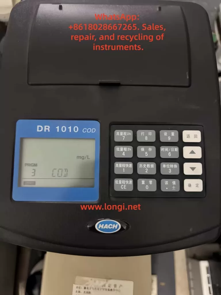
1.3 Keyboard Function Details
Program Selection Keys:
- High-range 2h: Selects the high-range two-hour digestion method; acts as the number key 7 in numeric mode.
- Low-range 2h: Selects the low-range two-hour digestion method; acts as the number key 4 in numeric mode.
- High-range rapid: Selects the high-range 15-minute digestion method; acts as the number key 1 in numeric mode.
- Low-range rapid: Selects the low-range 15-minute digestion method; acts as the number key 1 in numeric mode.
Function Keys:
- Print: Prints current data; acts as the number key 8 in numeric mode.
- Save: Stores the current reading; acts as the number key 5 in numeric mode.
- Historical data: Retrieves stored sample data; acts as the number key 2 in numeric mode.
- Zero: Uses the current sample blank for zero adjustment; acts as the number key 0 in numeric mode.
- Setup: Enters the setup menu; acts as the number key 9 in numeric mode.
- Time/Date: Displays the current time or date; acts as the number key 6 in numeric mode.
- Unit conversion: Converts between concentration, absorbance, and % transmittance; acts as the number key 3 in numeric mode.
- Read: Reads and displays the sample concentration; inputs decimal points or switches between positive and negative signs in numeric mode.
- Return: Cancels the current input or selection.
- △/▽: Scrolls up and down within the menu.
- Enter: Selects a menu item or accepts an input value.
Chapter 2: Initial Instrument Setup and Calibration
2.1 Battery Installation and Power Management
- Turn the instrument over and ensure the sample cell is empty.
- Open the battery compartment cover and install four AA alkaline batteries according to the markings.
- Re-cover the battery compartment and turn the instrument back to its upright position.
Important Tips:
- Use alkaline batteries. Do not use rechargeable Ni-Cd batteries.
- Replace all batteries when changing them.
- When the battery level is low, the LOW BATTERY icon will be displayed. Replace the batteries promptly.
- It is recommended to remove the batteries if the instrument is not used for an extended period.
2.2 Date and Time Setup
Date Setup:
- Press the “Setup” key to enter the SETUP menu.
- Select the DATE option and input the four-digit year, month, and day.
- Press the “Enter” key to confirm.
Time Setup:
- In the SETUP menu, select the TIME option.
- Input the time in 24-hour format.
- Press the “Enter” key to confirm.
2.3 Proper Use of Sample Tubes
- Wipe the outer surface of the sample tube with a lint-free cloth.
- Insert the tube into the instrument’s tube holder, with the HACH logo facing the display.
- Ensure consistent insertion direction for each measurement.
- Check that the sample tube is clean and free of scratches before measurement.
Chapter 3: Detailed Instrument Operation Procedures
3.1 Basic Measurement Steps
Determinator Setup:
- Upon startup, the instrument automatically enters the program used last time.
- Press the corresponding program key to select a program and press the “Enter” key to confirm.
Sample Preparation:
- Prepare the zero solution and the sample to be tested according to the program instructions.
Instrument Zeroing:
- Place the blank solution in the sample cell.
- Close the cover and press the “Zero” key.
- When the instrument displays 0 and the READ icon appears, measurement can begin.
Sample Measurement:
- Place the sample to be tested in the holder.
- Close the cover and press the “Read” key.
- The display shows the measurement result.
- Press the “Unit conversion” key to switch the display mode.
3.2 Standard Curve Adjustment Method
- Prepare standard solutions.
- Measure the standard solutions as samples in the program.
- After obtaining the readings, press the “Setup” key and scroll to the “STD” setting item.
- Input the actual concentration of the standard solution and press the “Enter” key.
Notes:
- Consider sample interference before adjustment.
- After adjustment, test multiple concentration standard solutions to verify the applicability of the curve.
- If the input calibration value is out of range, the instrument will emit a beep to indicate an error.
3.3 Data Storage and Retrieval
Data Storage:
- After the measurement result is displayed, press the “Save” key.
- The display shows the next available storage sequence number.
- Press the “Enter” key to accept or input a specific sequence number.
Data Retrieval:
- Press the “Historical data” key to enter the RECALL menu.
- Use the “▽” or “△” key or numeric keys to select the sample sequence number.
- Press the “Enter” key to display the stored data.
Chapter 4: Advanced Function Applications
4.1 User Program Creation Method
- Press the “Setup” key and select the USER option.
- Input the program number to be created (20-59).
- Select the wavelength.
- Prepare standard solutions and perform zero adjustment on the instrument.
- Measure the absorbance values of the standard solutions.
- Repeat the steps to complete the input of all standard points.
- Press the “Return” key and select to store the program.
Key Points:
- A minimum of 2 data points and a maximum of 12 are required.
- At 420nm, the absorbance should decrease as the concentration increases.
- At 610nm, the absorbance should increase as the concentration increases.
- The instrument will ignore identical absorbance values and emit a beep.
4.2 Data Transmission and Printing
Printer Connection:
- Connect the instrument and the printer using the gray data printing cable.
- Press the “Print” key to manually initiate printing.
Computer Connection:
- Connect the instrument and the computer using the black data transfer cable.
- Set the super terminal parameters.
- Start the text capture function.
- Press the “Print” key to transmit data to a text file.
4.3 Batch Data Processing
- Print all data: Select PRINT ALL in the SETUP menu.
- Delete all data: Select ERASE ALL in the SETUP menu.
- Data export: Transfer all data to a computer through the RS232 interface.
Chapter 5: Instrument Maintenance and Troubleshooting
5.1 Daily Maintenance Points
Cleaning and Maintenance:
- Wipe the instrument’s outer shell with a damp cloth.
- Promptly clean up any spilled reagents.
- Clean the sample cell holder with a cotton swab.
- Wipe the outer surface of the sample cell with lens paper or a soft, lint-free cloth.
Battery Management:
- Replace low-battery cells promptly.
- Remove the batteries if the instrument is not used for an extended period.
- Reset the date and time after replacing the batteries.
Storage Conditions:
- Storage temperature: -20 to 60°C
- Relative humidity: Below 80% (at 40°C)
- Avoid strong electromagnetic field environments.
5.2 Common Fault Exclusion
Error Codes and Solutions:
- Unable to set the instrument. Contact Hach customer service.
- Unable to read program data. Contact Hach customer service.
- Unable to write program data. Contact Hach customer service.
- Measurement battery error. Replace the batteries.
- Measurement A/D error. Contact Hach customer service.
- Measurement offset error. Check the installation of the light blocker.
- Low photometric intensity error. Check for light channel blockage or dilute the sample.
- Measurement value out of range. Confirm the installation of the instrument cover or contact customer service.
Other Common Problems:
- Concentration out of range: Dilute the sample and re-measure.
- Beep/error icon: Check the operational steps.
- Low battery level: The LOW BATTERY icon is displayed. Replace the batteries promptly.
Chapter 6: Safety Regulations and Quality Assurance
6.1 Safety Operation Regulations
Hazard Levels:
- Danger (DANGER): Situations that may lead to death or serious injury.
- Caution (CAUTION): Situations that may lead to minor or moderate injury.
- Note (NOTE): Information that requires special emphasis.
Key Safety Tips:
- Review the Material Safety Data Sheet (MSDS) and be familiar with safety procedures when handling chemical samples.
- The instrument should not be used for samples that are flammable or contain hydrocarbons.
- Do not use Ni-Cd rechargeable batteries.
- Do not open the instrument’s chassis without authorization.
6.2 Quality Assurance and Service Support
Quality Assurance:
- Most products are guaranteed for at least one year from the shipping date.
- The warranty covers defects in materials and manufacturing.
Repair Services:
- Users should not attempt to repair any parts other than the batteries by themselves.
- Contact an authorized Hach Company service center for repairs.
Chapter 7: Practical Application Tips and Experience Sharing
7.1 Best Practices for COD Measurement
Sample Handling Tips:
- Ensure the sample is representative and mix it thoroughly before sampling.
- Follow the digestion time and temperature requirements strictly.
- Use reagents from the same batch for comparative measurements.
Methods to Reduce Errors:
- Regularly verify the instrument’s accuracy using standard solutions.
- Keep the sample tube clean.
- Perform zero adjustment before each measurement.
- Take the average of multiple measurements of the same sample.
7.2 Handling Special Application Scenarios
High-Salinity Sample Measurement:
- May cause interference. It is recommended to conduct a spike recovery test.
- Establish a specific calibration curve if necessary.
Low-Concentration Sample Measurement:
- Use the low-range program to improve sensitivity.
- Extend the measurement time or increase the sample volume.
Chapter 8: Instrument Verification and Compliance
8.1 Performance Verification Methods
Blank Test:
- Measurement of ultrapure water should show 0mg/L COD.
Standard Sample Test:
- Use COD standard solutions with known concentrations for verification.
Repeatability Test:
- Measure the same sample multiple times and calculate the relative standard deviation.
Comparison Test:
- Compare the results with standard methods or other instruments.
8.2 Compliance Certification
LED Safety:
- Complies with EN60825-1 standard, Class 1 LED product.
Anti-Interference Characteristics:
- Complies with EN 50082-1 general anti-interference standard.
EMC Electromagnetic Compatibility:
- EN 61000-4-2 resistance to electrostatic discharge interference.
- EN 61000-4-3 resistance to radiated RF electromagnetic field interference.
- ENV 50204 resistance to digital telephone radiation.
Radio Frequency Emissions:
- Complies with EN 55011 (CISPR 11) Class B emission limits.
Conclusion
The Hach DR1010 COD Determinator is a powerful and easy-to-use professional water quality analysis instrument. Through systematic learning of this guide, users should be able to master all the functions of the instrument, from basic operations to advanced applications. Correct operational methods and regular maintenance not only ensure the accuracy of measurement data but also extend the instrument’s service life. When encountering problems that cannot be resolved, users should promptly contact Hach Company’s professional technical service personnel to avoid improper operations that may cause instrument damage or data loss.
With the continuous improvement of environmental protection requirements, the importance of COD monitoring is becoming increasingly prominent. It is hoped that this guide will help users fully leverage the performance advantages of the DR1010 COD Determinator and provide reliable technical support for water quality monitoring and environmental protection work.