Posted on

Comprehensive Evaluation and Maintenance Guide for the BioSpectrum AC Chemi HR 410 Gel Imaging System


Abstract

The BioSpectrum AC Chemi HR 410 is a versatile gel and chemiluminescence imaging platform widely used in molecular biology and biochemistry laboratories. This article synthesizes hardware specifications, software capabilities, common applications, troubleshooting methodologies, market pricing, installation considerations, and support resources into a coherent, step-by-step guide. Whether you’re commissioning a new system, refurbishing a second-hand unit, or diagnosing intermittent black-frame issues, this document provides the logical framework and detailed procedures to keep your imaging workflow running smoothly.


1. System Overview

The BioSpectrum AC Chemi HR 410 (often abbreviated “HR 410”) is manufactured by Analytik Jena (formerly UVP). It combines a fully enclosed dark chamber, interchangeable light sources, a high-sensitivity cooled CCD camera, and the user-friendly VisionWorks software. Typical applications include:

  • DNA/RNA electrophoresis imaging with EtBr or SYBR dyes
  • Protein blot detection via chemiluminescence (ECL) or fluorescence
  • Quantitative analysis of band densities (1D) and area densities (2D)
  • Plate and dish imaging using transmitted or reflected light

Key advantages are its modular optical design, precise filter-wheel control, and advanced image-processing algorithms. The system supports both manual and automated modes, making it suitable for single-user labs up to core facilities.


2. Hardware Components and Operating Principles

  1. Dark Chamber
    • Dimensions: ~445 mm (W) × 445 mm (D) × 813 mm (H). Completely light-tight to prevent ambient interference.
  2. Illumination Module (T-Lum Platform)
    • Houses ultraviolet (254 nm, 302 nm) or white LED arrays. Enables rapid switch-out of lamp assemblies.
    • Models labeled “Without T-Lum” require separate procurement of the light-source kit.
  3. Filter Wheel and Shutter
    • Motorized carousel holds multiple excitation and emission filters for fluorescence; includes an interlock shutter to block or permit light.
  4. CCD Camera (Chemi HR 2 MP)
    • High quantum-efficiency, Peltier-cooled CCD. Cooling reduces dark current, enabling long exposures (seconds to minutes) with minimal noise.
  5. Interface and Control
    • 230 VAC power input, USB and Ethernet ports. Can be tethered to a dedicated workstation or shared network PC.
  6. Chassis and Ergonomics
    • Top-mounted camera head with adjustable focus; front door for sample insertion; side vents for cooling airflow.

This modular architecture allows each component to be serviced or upgraded independently—critical for maintaining peak performance over years of operation.


The gel imaging system produces a black screen/image.

3. VisionWorks Software Features

VisionWorks is the proprietary acquisition and analysis suite for HR 410. Major modules include:

  • Acquisition Modes:
    • Preview: Real-time low-exposure view for focusing and framing.
    • Capture: Manual control of exposure time, gain, and shutter.
    • Auto-Exposure: Algorithmic calculation of optimal exposure based on selected template (e.g., DNA, chemiluminescence).
  • Image Management:
    • Zoom, pan, ROI selection, frame stacking, and pixel averaging to enhance weak signals.
  • Quantitative Analysis:
    • 1D Analysis: Automated lane/band detection, background subtraction, area integration.
    • 2D Area Density: Intensity heatmaps and contour plots for flat samples.
  • Template System:
    • Save and recall complete acquisition and analysis parameters for reproducible experiments.
  • Calibration Utilities:
    • Dark Reference Acquisition: Captures a baseline image with shutter closed to subtract sensor noise.
    • Flat Field Adjustment: Corrects for uneven illumination or vignetting across the field of view.

Intuitive menus and clear graphical feedback make VisionWorks accessible to both novice and expert users.


4. Common Application Workflows

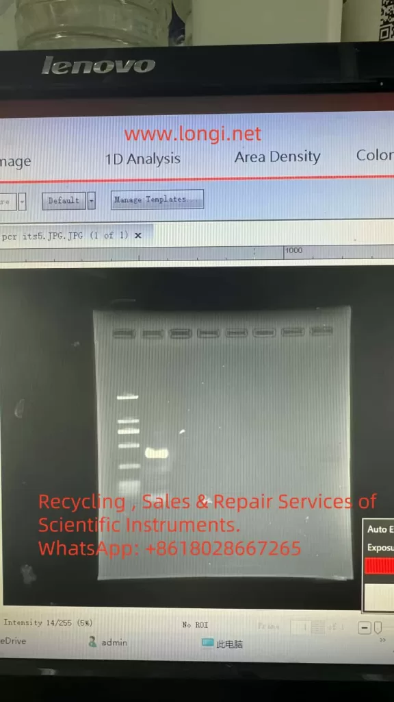
  1. Nucleic Acid Gel Imaging
    • Stain with Ethidium Bromide or SYBR dye; select appropriate excitation filter and emission barrier filter.
    • Use Preview to position the gel, then Auto-Exposure or manual exposure (0.5–10 s) depending on band brightness.
  2. Western Blot Chemiluminescence
    • Mount blot on trans-illumination tray, close door, then select “Chemiluminescence” template.
    • Exposures may range from 30 s to several minutes for low-abundance proteins.
  3. Quantitative Band Analysis
    • After capture, launch 1D Analysis: draw lanes, verify band boundaries, subtract local background, and export intensity values.
  4. High-Throughput Plate Imaging
    • Use white LED for trans-illumination of microplates; flat-field correction ensures uniform signal across wells.

These workflows can be chained in batch mode for unattended overnight acquisition.


The images captured by the gel imaging system are not clear.

5. Fault Phenomena and Root Cause Analysis

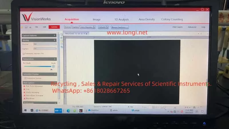
5.1 Completely Black Frames

  • Missing Illumination Module: Units sold “Without T-Lum” lack any light source; image is always black.
  • Lamp or LED Failure: Old or damaged bulbs/LEDs fail to ignite, leaving no excitation light.
  • Unready CCD Cooling: Camera not cooled to setpoint; software suspends exposure to avoid noise.
  • Filter or Shutter Misalignment: Filter wheel stuck in blank position or shutter never opens.

5.2 Intermittent Weak Signal

  • Lamp Aging: Mercury-arc bulbs degrade over time; sometimes they ignite, sometimes they don’t.
  • Calibration Expiry: Dark or flat references become outdated, leading to improper noise subtraction and vignetting artifacts.
  • Auto-Exposure Limitations: Default algorithms optimize for bright samples, missing faint chemiluminescence signals.

Understanding these categories allows targeted troubleshooting rather than trial-and-error.


6. Step-by-Step Troubleshooting and Maintenance Workflow

  1. Verify Illumination Presence
    • Check rear panel or documentation for T-Lum module; if absent, acquire and install the correct kit.
  2. Test and Replace Lamps/Ballasts
    • Preheat lamp for 5–10 min; observe light output. Measure ballast voltage. Replace any bulb nearing 800–1 000 h lifetime.
  3. Ensure CCD Cooling and Calibration
    • Wait for “Temperature: Ready” indicator. In the software, navigate to Image → Calibration and Acquire Dark Reference. Then enable Flat Field Adjustment.
  4. Optimize Exposure Settings
    • Run Auto-Exposure in the “Chemiluminescence” template. If still dim, manually increase exposure to 60–300 s. Disable “Compensate exposure for” to test pure manual mode.
  5. Maintain Filter Wheel and Shutter
    • Cycle through all filter positions in software; listen for smooth motor sounds. Clean filter edges and apply micro-drops of non-oil lubricant to bearings as needed.
  6. Update Software and Firmware
    • Download the latest VisionWorks patches and camera firmware from the manufacturer’s website. Reboot system to apply changes.
  7. Clean Optical Path and Sample Holders
    • Wipe lenses, trays, and windows with lint-free wipes and 70% ethanol. Verify that sample trays align with the camera’s field of view.

By following this structured workflow, most “black frame” or “fluctuating signal” issues can be resolved without resorting to full system teardown.


7. Market Selection and Pricing Reference

ConfigurationTypical Second-Hand Price (USD)New Unit MSRP (USD)Notes
Dark Chamber Only (no camera, no software)800 – 1 500N/AFor UV fluorescence only, no chemiluminescence
Refurbished Complete System (HR 410 + Software)5 000 – 6 000N/AOften sold with limited warranty
Brand-New Complete System (HR 410 + License + T-Lum)N/A8 000 – 12 000Official distributor pricing

Recommendation:

  • Budget-Conscious Labs: Opt for a fully refurbished unit with warranty coverage.
  • Core Facilities or High-Throughput Settings: Invest in a brand-new system for guaranteed support, full warranty, and latest firmware.

8. Installation Footprint and Environmental Requirements

  • Dark Chamber Dimensions: 445 mm × 445 mm × 813 mm
  • Overall Footprint (including camera head): 623 mm × 463 mm × 915 mm
  • Space Planning: Reserve at least 300 mm clearance front and back, 500 mm on sides for maintenance access.
  • Ambient Conditions:
    • Temperature: 18 °C – 25 °C
    • Relative Humidity: ≤ 60%
    • Avoid direct sunlight or strong fluorescent lighting near the sample door.

Proper environmental control reduces temperature fluctuations on the CCD and extends component life.


9. Supporting Documentation and Technical Assistance

  • Official Manual: BioSpectrum Imaging System Instruction Guide (Part 81-0346-01 Rev J) contains detailed hardware schematics, software installation, calibration procedures, and maintenance guidelines.
  • Key Chapters to Review:
    1. Hardware Setup and Power Connections
    2. VisionWorks Installation and License Activation
    3. Acquisition Modes and Template Management
    4. Dark/Flat Reference Procedures
    5. Advanced Troubleshooting (lamp, ballast, cooling system)
  • Technical Support Channels:
    • Contact Analytik Jena’s regional distributor for spare parts (lamps, filters, shutters).
    • Access online firmware updates and knowledge-base articles via the official website.
    • Enroll in extended service contracts for on-site preventive maintenance.

10. Conclusion and Best Practices

The BioSpectrum AC Chemi HR 410 combines optical versatility, sensitive detection, and powerful analysis software to serve a broad range of life-science imaging applications. By adhering to the systematic maintenance workflow outlined above, users can:

  1. Prevent Downtime: Regular lamp replacement, calibration refreshes, and filter-wheel lubrication.
  2. Ensure Data Quality: Proper dark/flat corrections and exposure optimization guarantee reproducible results.
  3. Extend System Life: Keeping software and firmware up to date, cleaning optical components, and controlling environmental factors.

When selecting a unit, balance budgetary constraints against the need for warranty and technical support. For intermittent imaging issues—such as occasional black frames or weak signals—follow the seven-step troubleshooting procedure before involving service engineers. In doing so, your laboratory will realize maximum uptime, consistent image quality, and reliable quantitative data for years to come.

Posted on

Analysis and Handling of the ILF Fault Code in Schneider ATV61 Inverters

1. Meaning and Essence of the ILF Fault Code

1.1 Definition of the ILF Fault Code

The ILF fault code in Schneider ATV61 inverters stands for “Internal Link Fault.” Specifically, the ATV61 inverter comprises two main components: the control card and the power card. The control card is responsible for logical operations and parameter control, while the power card drives the motor. These two components communicate via an internal communication link, typically a high-speed communication bus. When this communication link encounters issues, the inverter detects the anomaly and triggers the ILF fault code, halting operation to protect the equipment.

1.2 Essence of the ILF Fault

From a technical perspective, the essence of the ILF fault is an interruption or data transmission error in the communication between the inverter’s control card and power card. This communication interruption can be caused by several factors:

  • Hardware Issues: Loose, damaged, or poor physical connections (such as communication cables or connectors) between the control card and the power card.
  • Component Failure: Hardware damage to the control card or power card, such as burnt chips or aging circuit boards.
  • Electromagnetic Interference (EMI): External EMI or poor grounding causing unstable communication signals.
  • Firmware Issues: Incompatible or corrupted firmware versions between the control card and power card, leading to the inability to execute communication protocols properly.
ILF

The occurrence of an ILF fault typically results in the inverter stopping operation and alerts the user via the display or status indicators (such as RUN, CAN, and ERR lights).

2. Possible Causes of the ILF Fault

2.1 Hardware Connection Issues

The control card and power card within the ATV61 inverter are connected via dedicated communication cables or connectors. If these connections become loose, poorly contacted, or damaged during operation, communication will be interrupted.

2.2 Control Card or Power Card Failure

The control card and power card are core components of the inverter. If either card’s hardware fails (e.g., chip damage or circuit board burnout), the communication link will not function properly.

2.3 Electromagnetic Interference

Inverters are often installed in industrial environments with high-power equipment, motors, or other sources of electromagnetic interference. If the inverter’s grounding is inadequate or shielding measures are insufficient, communication signals may be disrupted.

2.4 Incompatible or Damaged Firmware

If firmware upgrades fail or the firmware versions of the control card and power card are mismatched, the communication protocol may not execute correctly, triggering the ILF fault.

2.4 Other Potential Factors

  • Environmental Factors: High temperatures, humidity, or dust may cause internal components to age or short-circuit.
  • Misoperation: Users may accidentally set incorrect parameters or damage hardware during debugging or maintenance.
  • Power Issues: Abnormal input power may interfere with the normal operation of the inverter.

3. Handling Methods for the ILF Fault

3.1 Preliminary Checks and Safety Preparations

  • Power Off: Turn off the inverter’s power and wait at least 5 minutes to ensure the internal capacitors discharge completely.
  • Wear Protective Gear: Wear insulating gloves and shoes, and use appropriate tools.
  • Record Fault Information: Record the inverter’s model, firmware version, and fault details.

3.2 Check Hardware Connections

  • Check Internal Communication Cables: Ensure cables are not loose, broken, or have poor contact. Reinsert or replace them if necessary.
  • Check Connectors: Clean connectors to ensure good contact.
ATV61

3.3 Investigate Control Card and Power Card Failures

  • Replacement Testing: Replace the control card or power card one by one to test if the fault disappears.
  • Check Hardware Status: Inspect for obvious physical damage.

3.4 Reduce Electromagnetic Interference

  • Check Grounding: Ensure grounding resistance is less than 4 ohms.
  • Shielding Measures: Add shielding covers or adjust equipment layout.
  • Check Power Quality: Measure input power voltage and frequency, and install power filters if necessary.

3.5 Check Firmware Versions

  • View Firmware Information: Confirm that the firmware versions of the control card and power card match.
  • Firmware Recovery or Upgrade: Download the latest firmware from Schneider’s official website and upgrade.

3.6 Reset the Inverter

  • Power Cycle: Reconnect power and observe if the fault disappears.
  • Restore Factory Settings: Reset to factory settings via the menu [1.8 Fault Management] (FLt-) to restore factory settings.

3.7 Contact Technical Support

  • Contact Us for Handling: If the above steps fail, seek professional help.
  • Provide Information: Prepare the inverter model, firmware version, and fault details.

4. Suggestions for Preventing ILF Faults

  • Regular Maintenance: Inspect internal connections and cleanliness every six months.
  • Optimize Operating Environment: Ensure proper ventilation and temperature control.
  • Standardized Operation: Follow the user manual strictly.
  • Monitor Power Quality: Regularly check the stability of the input power supply.

5. Summary

The ILF fault reflects abnormalities in the internal communication link of the ATV61 inverter. Through systematic troubleshooting methods and preventive measures, users can effectively resolve issues and ensure the stable operation of the equipment.

Posted on

Mitsubishi FR-A700 Inverter E.ou2 Fault: Analysis and Solutions for Overvoltage During Constant Speed Operation

Abstract

This article provides a detailed analysis of the E.ou2 fault (overvoltage during constant speed operation) in the Mitsubishi FR-A700 series inverter. By integrating manual content with real-world application scenarios, it explores the causes, troubleshooting steps, and solutions to help users quickly diagnose and resolve the issue, ensuring stable equipment operation.

Keywords

Mitsubishi FR-A700, E.ou2 fault, overvoltage during constant speed, inverter, regenerative energy

1. Introduction

The Mitsubishi FR-A700 series inverters are widely recognized for their excellent performance in industrial motor control, particularly in applications like injection molding machines. However, during operation, inverters may trigger fault codes such as the user-reported “E.ou2.” According to the manual and the screenshot provided by the user, E.ou2 indicates an “overvoltage during constant speed operation,” meaning the main circuit DC voltage exceeds a safe threshold during fixed-speed operation, activating the protection mechanism. This article delves into this fault and offers practical solutions.

E.OU2

2. Definition and Causes of the E.ou2 Fault

The E.ou2 fault is a protective error code in the Mitsubishi FR-A700 inverter, specifically denoting “overvoltage during constant speed operation.” When the inverter detects that the main circuit DC voltage surpasses the specified limit (typically related to the power supply voltage and device configuration, e.g., a threshold in a 400V system), it automatically stops output to safeguard the equipment. The primary causes of this fault include:

  • Excessive Regenerative Energy: During constant speed operation, the motor may generate significant regenerative energy due to load characteristics or mechanical inertia, feeding back into the inverter’s DC bus and raising the voltage.
  • Improper Parameter Configuration: For instance, if Pr.22 (stall prevention operation level) is set too low, it may fail to effectively suppress voltage fluctuations.
  • Abnormal Power or Load: Unstable power supply voltage or sudden load changes (e.g., process adjustments in an injection molding machine) may exacerbate regenerative energy production.

3. Fault Manifestations and Real-World Case

Based on the user-provided image, the inverter display clearly shows the “E.ou2” error code with the “RUN” light off, indicating that the device has stopped. This issue may occur in the following scenarios:

  • Time Pattern: The user noted that the equipment runs normally in the morning but frequently faults at noon, possibly due to rising environmental temperatures or changes in production load.
  • Industrial Environment: The image reveals dust accumulation on the inverter’s surface, suggesting prolonged operation in a harsh environment, which may impair heat dissipation and worsen the fault.

4. Troubleshooting and Solutions

To effectively address the E.ou2 fault, users are advised to follow these step-by-step troubleshooting and improvement measures:

4.1 Parameter Check and Adjustment
  • Pr.22 (Stall Prevention Operation Level): Verify that this parameter is not lower than the motor’s no-load current. If it is, adjust it to a value higher than the no-load current to prevent erroneous protection triggers.
  • Pr.882 ~ Pr.886 (Regenerative Feedback Function): Enable and optimize these parameters to manage regenerative energy effectively. Refer to page 365 of the manual for specific settings.
4.2 External Equipment Optimization
  • Braking Unit: If regenerative energy is significant, installing a braking unit to dissipate excess energy through resistors is recommended.
  • Common DC Bus Converter (FR-CV): For frequent overvoltage issues, using an FR-CV can efficiently absorb regenerative energy.
  • Power Supply Inspection: Use a multimeter or oscilloscope to check the input power stability, ensuring voltage fluctuations stay within the inverter’s allowable range.
4.3 Environmental Improvements
  • Heat Dissipation Management: Ensure proper ventilation for the inverter, adding fans or air conditioning, especially during high-temperature periods (e.g., noon).
  • Cleaning Maintenance: Regularly remove dust from the inverter’s surface to prevent poor heat dissipation from causing cascading issues.
4.4 Data Logging and Analysis
  • Operation Log: Record data such as load, speed, and environmental temperature at the time of the fault to identify potential patterns.
  • Fault History: Use the inverter’s MON mode to review historical fault records for diagnostic support.
FR-A700

5. Case Analysis and Recommendations

Based on the user’s feedback and image data, the frequent occurrence of the E.ou2 fault at noon may be linked to the following factors:

  • Temperature Impact: Rising environmental temperatures at noon reduce heat dissipation efficiency, making DC bus voltage more likely to exceed limits.
  • Load Fluctuations: Production process adjustments may lighten the load, increasing regenerative energy.
    For this scenario, the following recommendations are suggested:
  1. Enhance heat dissipation measures during high-temperature periods, such as temporarily adding fans.
  2. Investigate load characteristics during noon hours and adjust operating parameters or processes as needed.
  3. Implement regular maintenance to ensure long-term equipment stability.

6. Conclusion

The E.ou2 fault is a common overvoltage issue in Mitsubishi FR-A700 inverters during constant speed operation. By optimizing parameter settings, installing external equipment, improving heat dissipation, and conducting regular maintenance, users can significantly reduce fault occurrence and enhance equipment reliability. The troubleshooting steps and solutions provided in this article are universally applicable to similar scenarios.

7. References

  • Mitsubishi FR-A700 Series Inverter User Manual

Posted on

Analysis and Solutions for F085 Fault in Rockwell PowerFlex 700 Series Inverters

Introduction

Rockwell Automation, a global leader in industrial automation solutions, is well-regarded for its high-performance and reliable PowerFlex series inverters. The PowerFlex 700 series, suitable for various applications such as machine tools, conveyor systems, fans, and pumps, is widely used in industrial settings. However, in complex industrial environments, inverters may encounter faults due to various reasons, with the F085 fault code being a common issue faced by users. This article provides a detailed analysis of the meaning, causes, and solutions for the F085 fault based on the PowerFlex 700 series inverter user manual (Chinese version) and relevant technical resources, offering practical guidance to users.

powerflex700

Meaning of the F085 Fault Code

According to the PowerFlex 700 series inverter user manual (Chinese version), the F085 fault code indicates an “External Fault.” This fault is triggered by an abnormal signal sent to the inverter via a digital input (DI) from an external device. When the inverter detects an abnormal signal from an external device (such as a PLC, sensor, or other control device) through its digital input terminals, it triggers the F085 fault, leading to inverter shutdown or an alarm.

It is important to note that some English versions of the manual may describe F085 as “DPI Port 1-5 Loss,” indicating potential variations in fault code descriptions across different versions or languages. This article adheres to the Chinese manual provided by the user, defining F085 as an “External Fault.” Users should confirm the manual version in actual operations to ensure accuracy in fault code interpretation.

Causes of the F085 Fault

The triggering of the F085 fault is typically related to external devices, wiring, or inverter configuration. The following are possible causes:

External Device Failure

  • External devices connected to the inverter’s digital inputs, such as PLCs or sensors, may send erroneous signals due to hardware failures or misoperations. For example, sensors may output abnormal signals due to environmental interference or damage.
  • Incorrect configuration of external devices (e.g., PLC program logic errors) may also lead to the inverter misinterpreting signals as external faults.

Wiring Issues

  • Wiring between external devices and the inverter’s digital input terminals may be loose, short-circuited, or open-circuited, resulting in abnormal signal transmission.
  • Dust, corrosion, or mechanical vibration affecting the wiring terminals may cause poor contact.

Parameter Configuration Errors

  • The inverter’s digital input parameters (e.g., parameters 361-366 for “Digital Input 1-6 Selection”) may not be correctly configured, leading to the inverter misinterpreting external signals.
  • If digital inputs are set to detect external faults but the external devices do not correctly match the signal logic, the F085 fault may be triggered.

HIM (Human-Machine Interface) Connection Problems

  • If an HIM is used for control, unstable connections between the HIM and the inverter may result in signal transmission interruptions or false fault triggers.
  • Damage to the HIM device itself may also indirectly affect fault detection.

External Signal Logic Issues

  • The signal logic (e.g., high or low level) sent by external devices may not match the inverter’s expectations, leading to false triggers of the F085 fault.

Solutions for the F085 Fault

To effectively resolve the F085 fault, users can follow these steps for troubleshooting and handling:

1. Check External Devices

Steps: Inspect external devices connected to the inverter’s digital inputs (e.g., PLCs, sensors) for normal operation.

Operations:

  • Confirm whether the devices are sending fault signals and check their status for normal operation.
  • If a device outputs a fault signal, verify whether it is a genuine fault or a false alarm.
  • Replace or repair external devices as necessary.

Note: Ensure that the operating environment of the devices (e.g., temperature, humidity) meets requirements to avoid interference.

2. Check Wiring

Steps: Verify that the wiring between external devices and the inverter’s digital input terminals is secure.

Operations:

  • Check for loose, short-circuited, or open-circuited wiring terminals.
  • Use a multimeter to test wiring continuity and ensure no poor contact exists.
  • Refer to the user manual’s wiring diagrams to ensure compliance with specifications.

Note: Disconnect the power supply before operations to ensure safety.

3. Verify HIM Connection

Steps: If an HIM is used for control, check the connection between the HIM and the inverter.

Operations:

  • Ensure that the HIM connection cables are secure and that the connection ports are clean.
  • Try reinserting the HIM or replacing the HIM device.

Note: HIM connection issues may indirectly affect fault triggers and require careful troubleshooting.

4. Check and Adjust Parameter Settings

Steps: Access the inverter’s parameter setup menu and check digital input-related parameters.

Operations:

  • Check parameters 361-366 (Digital Input 1-6 Selection) to confirm which input triggered the F085 fault.
  • If external fault detection is not required, set the relevant parameters to “Disabled” or “No Function” (e.g., set to 0).
  • Check parameters 17 (Digital Input Configuration) and 18 (Digital Input Logic) to ensure signal logic matches.

Example Parameter Table:

Parameter NumberDescriptionPossible Settings
361-366Digital Input 1-6 SelectionSet to 0 (No Function) to disable external fault
17Digital Input ConfigurationEnsure matching with external device signals
18Digital Input LogicAdjust logic (e.g., high/low level)

5. Adjust Fault Mask Parameters

Steps: Check fault mask parameters to屏蔽 (mask) the F085 fault.

Operations:

  • Locate parameter 4 (External Fault) or relevant fault mask parameters.
  • Set it to “Disabled” (e.g., 0) to prevent the F085 fault from triggering shutdown or an alarm.
  • Save parameter settings (usually through parameter 30 “Parameter Save”).

Note: Specific parameter values should be referenced from the user manual.

powerflex700

6. Reset the Fault

Steps: After resolving the issue, clear the fault.

Operations:

  • Select the “Fault Clear” option through the HIM or control panel.
  • Alternatively, power off and restart the inverter (ensure safe operation).

Note: Ensure that the root cause has been resolved before resetting.

7. Further Diagnosis

Steps: If the issue remains unresolved, use diagnostic tools or contact technical support.

Operations:

  • Use a SCANport device to check the communication status between the inverter and external devices.
  • Contact us for professional assistance.

Preventive Measures

To prevent the recurrence of the F085 fault, the following measures can be taken:

Regular Maintenance

  • Regularly inspect external devices and wiring status to ensure reliable connections.
  • Clean wiring terminals to prevent dust or corrosion from affecting signal transmission.

Correct Parameter Configuration

  • During initial setup, ensure that digital input parameters match external devices.
  • If external fault detection is not used, disable relevant functions in advance.

Monitor System Status

  • Regularly check the inverter’s operating status using an HIM or other tools and record abnormal logs.
  • Establish a fault warning mechanism to detect potential issues promptly.

Train Operators

  • Provide training to ensure that operators are familiar with inverter operation and fault handling.
  • Update knowledge of new manual versions and parameter settings.

Backup System Configuration

  • Regularly back up inverter parameters for quick recovery after faults.

Conclusion

The F085 fault in the PowerFlex 700 series inverter typically indicates an “External Fault” triggered by an external device via a digital input. By checking external devices, wiring, parameter settings, and making necessary adjustments, the fault can be effectively resolved. Regular maintenance and correct configuration are key to preventing faults. Users should refer to specific chapters in the PowerFlex 700 user manual (Chinese version) and conduct troubleshooting based on actual application scenarios. If the issue is complex, it is recommended to contact us for further guidance.

Posted on

AUT-DRIVE DV6000 VFD (Variable Frequency Drive) User Guide and E-03 Fault Solution


I. Operation Panel Functions and Basic Settings

1. Operation Panel Function Introduction

  • Key Functions:
    • RUN Key: Starts the VFD operation; requires configuration of the operation command channel.
    • STOP/RESET Key: Stops the device during operation or resets alarms during fault states.
    • PRG Key: Enters the parameter editing menu, supporting three-level menu navigation (Function Group → Function Code → Parameter Value).
    • Direction Keys (▲/▼): Switches between displayed parameters or adjusts values, supporting cyclic selection and bit modification.
    • FUN Key: Can be customized for jog operation or forward/reverse switching (configured via F7.03).
  • Display Area:
    • 5-Digit LED Display: Shows operating frequency, fault codes, parameter values, etc.
    • Status Indicators: Include operating status (RUN/TUNE), forward/reverse (FWD/REV), local/remote control (LOCAL/REMOTE), and fault (TRIP) indicators.

2. Restoring Factory Default Settings

  • Steps:
    1. Navigate to Function Group F0 → Select F0.13 (Function Parameter Restore).
    2. Set to 1 (Restore Factory Defaults) → Press the confirmation key (ENT) to save.
  • Note: After restoration, key parameters (e.g., motor nameplate data, control mode) must be reconfigured.

3. Password Setup and Access Restrictions

  • Setting Password: Input a 4-digit number (range 0~65535) via F7.00 (User Password); non-zero values take effect.
  • Removing Password: Set F7.00 to 0 or restore factory defaults.
  • Parameter Access Restrictions:
    • A valid password is required to enter editing mode (display “PASS” before input).
    • Some parameters (marked with “-“) are manufacturer-specific and cannot be modified by users.

E-03

II. External Terminal Control and Speed Adjustment Settings

1. External Terminal Forward/Reverse Control

  • Terminal Connections:
    • Forward Terminal: X1 (default function code F5.04=1).
    • Reverse Terminal: X2 (default function code F5.05=2).
    • Common Terminal: COM.
  • Parameter Settings:
    1. Set F0.01 (Operation Command Channel) to 1 (Terminal Command Channel).
    2. Configure F5.07 (Terminal Control Mode):
      • 0 (Two-Wire Control): X1 for forward, X2 for reverse; both closed stops the drive.
      • 1 (Three-Wire Control): Requires an additional terminal as an enable signal (e.g., configure X3 as “Three-Wire Operation Control”).

2. External Potentiometer Speed Adjustment

  • Terminal Connections:
    • Potentiometer Signal Input: VS1 (0~10V) or VS2 (0~10V/4~20mA, selected via jumper).
    • Signal Ground: GND.
  • Parameter Settings:
    1. Set F0.03 (Frequency Command Selection) to 2 (Analog VS1) or 3 (Analog VS2).
    2. Calibrate Input Range (Optional): Adjust F5.09~F5.12 (VS1 Upper/Lower Limit Corresponding Values) to ensure 0~10V corresponds to 0%~100% frequency.
    3. For current signals (4~20mA), switch VS2 jumper to current mode (JP2 position).

III. E-03 Fault Analysis and Solution

1. Fault Definition and Symptoms

  • E-03 Fault: Overcurrent during constant-speed operation, triggering protective shutdown. The LED display shows “E-03” and flashes.

2. Possible Causes

  • Load Sudden Change: Mechanical jamming, abnormal drive system (e.g., gear damage).
  • Power Supply Abnormality: Input voltage fluctuations or instantaneous drops.
  • Improper Parameter Configuration: Motor parameters (Group F2) do not match actual values, or carrier frequency (F0.11) is set too high.
  • Hardware Issues: Abnormal current detection circuit, aged IGBT module.

3. Solution Steps

  • Step 1: Check Load and Mechanical System
    • Disconnect the motor from the load and test under no-load conditions to check if the fault persists.
    • Inspect couplings and bearings for jamming; eliminate mechanical abnormalities.
  • Step 2: Optimize Parameter Configuration
    • Adjust F0.11 (Carrier Frequency): Reduce the carrier frequency (e.g., from 8kHz to 4kHz) to reduce switching losses.
    • Calibrate Group F2 (Motor Parameters): Perform motor self-learning (F0.12=1 or 2) to ensure accurate stator resistance and inductance values.
  • Step 3: Check Power Supply and Hardware
    • Measure three-phase input voltage to ensure balance deviation <15%.
    • Detect DC bus voltage; if abnormal fluctuations occur, install an input reactor.
    • Troubleshoot current sensor (Hall element) or drive circuit faults; replace modules if necessary.

4. Preventive Measures

  • Regularly clean the cooling fan to ensure the inverter module temperature (F7.09) <85°C.
  • Enable F8.07 (Automatic Current Limiting Function) and set the current limiting level (F8.07=150%) to suppress sudden overcurrents.

DV6000

IV. Conclusion

The AUT-DRIVE DV6000 VFD offers flexible parameter configuration and terminal control functions to meet complex industrial requirements. Operators must strictly follow the manual instructions, perform regular maintenance, and record operational data. For E-03 faults, systematically troubleshoot load, power supply, parameter, and hardware issues, combined with function code adjustments and mechanical maintenance, to ensure stable device operation. Password protection and parameter access restrictions further enhance equipment management security.

Posted on

User Guide for Siemens V20 Frequency Converter Based on the User Manual

Operation Panel Function Introduction

The Basic Operation Panel (BOP) of the Siemens V20 frequency converter serves as the primary interface for user interaction, integrating multiple critical functions. It provides real-time monitoring of key parameters including operating frequency, output current, and DC bus voltage, displayed on a high-brightness LED screen with two-line readability up to 1.5 meters. The membrane keypad design includes six functional keys:

  • OFF1 Stop Key: Initiates ramp stop by single press, decelerating the motor to stop according to preset deceleration time (P1121).
  • Start/Reverse Key: Controls motor start/stop in manual mode, with long-press (2 seconds) for direction reversal.
  • Multi-Function Key (M): Navigates menus, confirms parameter edits, switches display screens, and initiates bit editing when combined with OK key.
  • OK Key: Enables mode switching, rapid parameter confirmation, and password entry (long-press for 3 seconds).
  • Direction Keys: Traverses menu hierarchy, adjusts parameter values, and fine-tunes frequency settings; scrolls fault history in alarm state.
  • Fault Reset Key: Integrated with OK key functions through combination operations.

The panel adopts a three-level menu structure with four main modules: Operation Status, Parameter List, Fault Records, and System Settings. In parameter editing mode, bit-by-bit modification is supported with rapid saving via OK key. Notably, the BOP supports offline parameter backup through dedicated interfaces.

Parameter Initialization and Security Settings

Parameter Initialization Procedure

V20

The Quick Commissioning function enables parameter reset and basic configuration:

  1. Enter P0010=1 commissioning mode
  2. Configure motor parameters (P0304-P0311)
  3. Select connection macro (Cn001 for terminal control or Cn002 for communication control)
  4. Set application macro (e.g., P1300=20 for fan/pump loads)
  5. Execute P3900=1 to complete calculations

This process automatically configures over 20 core parameters including ramp functions and overload protection, reducing commissioning time by 60% compared to traditional methods.

Access Control Mechanism

The V20 converter employs a hierarchical access management system:

  • Access Level (P0003): Five levels from 0 (user-defined) to 4 (service)
  • Parameter Group Locking: Restricts accessible parameter groups via P0004
  • Password Protection: 4-digit password required for critical parameter modifications at expert level (3)

To remove password protection, downgrade P0003 to level 2 or below, or reset via service interface using specialized tools. Access restrictions can be applied to individual parameters, such as allowing P1080 (minimum frequency) adjustments while blocking P1120 (acceleration time) modifications.

External Control Implementation

Forward/Reverse Terminal Control

Utilizing digital input terminals (DI1-DI4) for direction control:

  1. Wiring Configuration: Connect DI1 for forward command (24VDC) and DI2 for reverse command
  2. Parameter Settings:
    • P0701=1 (DI1 as ON/OFF1 command)
    • P0702=2 (DI2 as reverse command)
    • P0700=2 (command source set to terminal control)
    • P1000=3 (frequency source set to analog input)

This configuration supports pulse commands for forward/reverse operations, automatically executing deceleration-stop-reverse acceleration sequence to prevent mechanical shocks.

Potentiometer Speed Control

Implementing analog input terminal (AI1) for stepless speed regulation:

  1. Wiring Requirements: Connect 10kΩ linear potentiometer with mid-tap to AI1 (10V power supplied by converter)
  2. Parameter Configuration:
    • P0756=2 (AI1 set to 0-10V voltage input)
    • P1000=2 (frequency source set to analog input)
    • P1080=5Hz (minimum frequency)
    • P1082=50Hz (maximum frequency)
    • P0759=0 (zero calibration)
    • P0760=100% (full-scale calibration)

Input filtering time (P0771) is recommended at 50ms to suppress interference pulses from contactor operations.

V20

Fault Diagnosis and Resolution

Typical Fault Code Reference

Fault CodeDescriptionPossible CausesSolutions
F1OvercurrentMotor cable short, short acceleration timeCheck insulation, extend P1120
F3UndervoltagePower supply fluctuation, braking resistor shortVerify power quality, check R0001 resistor
F4Converter OverheatPoor ventilation, high pulse frequencyClean air ducts, reduce P1800 carrier frequency
F12Temp Sensor FaultTemperature detection circuit openCheck T1/T2 terminal connections
F54Motor I²t OverloadProlonged overload operationReduce load, adjust P610 thermal time constant
F79Motor StallMechanical jamming, sudden load changeCheck transmission, optimize P1237 stall detection time

Systematic Fault Handling

  1. Fault Verification: Check current fault code and timestamp via BOP
  2. Parameter Backup: Execute P0971=1 to prevent data loss during troubleshooting
  3. Root Cause Analysis:
    • Electrical Issues: Measure terminal resistance (phase-to-phase insulation >1MΩ)
    • Mechanical Issues: Verify coupling alignment (allowable deviation <0.05mm)
    • Parameter Anomalies: Compare with P0005 parameter change history
  4. Recovery Procedure:
    • Temporary Fix: Restore factory settings via P0970=1 (after backup)
    • Permanent Repair: Replace components or optimize control logic per fault code guidance

Maintenance and Optimization Recommendations

  1. Preventive Maintenance:
    • Clean cooling fans every 2000 operating hours
    • Calibrate potentiometer linearity quarterly (error <2%)
    • Perform insulation resistance test annually (≥1MΩ@500VDC)
  2. Energy Efficiency:
    • Enable P1300=20 fan/pump macro for automatic V/f² characteristic
    • Match P1120/P1121 ramp times with load inertia
    • Activate P3300=1 energy-saving mode for automatic frequency reduction at no-load
  3. Communication Expansion:
    • Enable USS protocol via P2010[0]=1
    • Configure P2011=9.6kbps baud rate
    • Set Modbus address mapping using P2021-P2024

This guide is based on V20 firmware version V4.7.16. Always refer to the manual corresponding to your device’s firmware version. Execute parameter backup via P0971=1 before critical modifications and manage versions with P0970=2. For complex applications, use STARTER tool for offline programming and online monitoring.

Posted on

SJZO Frequency Inverter 200M Series User Manual & E.04 Fault Solution

I. Product Overview & Core Features

The SJZO Frequency Inverter 200M Series is a high-performance vector control inverter designed for industrial automation, widely applied in motor speed regulation, energy-saving control, and precision drive scenarios. Its core advantages include a wide power range (0.4kW–500kW), high-precision control algorithms, and multifunctional interface design. This guide provides detailed instructions on operating panel functions, parameter setup techniques, external control implementation methods, and common fault troubleshooting.


II. Operating Panel Functions & Parameter Management

1. Operating Panel Overview

The SJZO 200M Series features an intuitive LCD operating panel supporting the following core functions:

  • Start/Stop Control: Directly start or stop the motor via panel buttons.
  • Frequency Setting: Adjust output frequency (0–400Hz) via a knob or digital input.
  • Parameter Display & Modification: View real-time parameters such as current, voltage, and fault codes.
  • Mode Switching: Toggle between local control (panel operation) and remote control (external signals).
SJZO

2. Password Setup & Removal

(1)Setting a Password

  • Access parameter group P7 (Access Control) and locate parameter P7.01 (User Password).
  • Enter a 4-digit password (e.g., 1234) and press “Confirm” to save.
  • Once enabled, critical parameter modifications require password input.

(2)Removing the Password

  • Access P7.01, enter the set password, and change the value to “0000” to remove it.

3. Parameter Access Restrictions

  • Hierarchical Access Control:
    • Parameter group P7.02 allows setting different access levels (e.g., Engineer Level, Operator Level) to restrict unauthorized parameter modifications.
    • Example: Setting P7.02 to “1” allows viewing only basic parameters; setting it to “2” grants full parameter modification access.

4. Restoring Factory Default Settings

  • Method 1: Panel Operation
    • Press and hold the “Reset” button for 5 seconds until “INI” appears on the screen, then release. Parameters will automatically revert to defaults.
  • Method 2: Parameter Setup
    • Access parameter P0.15 (Factory Reset), set it to “1,” and confirm. The inverter will restart with default settings.

III. External Terminal Forward/Reverse Control & Potentiometer Speed Regulation

1. External Terminal Forward/Reverse Control

(1)Wiring Instructions

  • Forward Terminal (e.g., X1): Connect to an external switch signal (normally open contact). Closing the contact starts the motor in the forward direction.
  • Reverse Terminal (e.g., X2): Connect to another switch signal. Closing the contact starts the motor in reverse.
  • Common Terminal (COM): Provides a reference ground for control signals.

(2)Parameter Setup

  • Control Mode Selection:
    • Set P0.01=1 (External Terminal Control Mode).
  • Terminal Function Definitions:
    • Set P4.01=1 (X1 as Forward Command), P4.02=2 (X2 as Reverse Command).
  • Interlock Protection:
    • Enable P4.10=1 (Forward/Reverse Interlock) to prevent simultaneous activation and short circuits.

2. External Potentiometer Frequency Regulation

(1)Wiring Instructions

  • Potentiometer Connection:
    • Connect the potentiometer ends to the inverter’s +10V (power supply) and GND (ground), and the wiper to the analog input terminal AI1 (or AI2).
  • Signal Range: 0–10V corresponds to an output frequency range of 0–50Hz (adjustable).

(2)Parameter Setup

  • Frequency Source Selection:
    • Set P0.02=2 (Analog Input AI1 as Frequency Setting Source).
  • Input Range Calibration:
    • Set P3.01=0 (0–10V input), P3.02=50.00 (corresponding to a maximum frequency of 50Hz).
  • Filtering Time:
    • Adjust P3.05=0.1s (to reduce signal jitter interference).

E.04

IV. E.04 Fault Code Analysis & Troubleshooting

1. Fault Definition

E.04 indicates “Output Overcurrent,” meaning the inverter detects motor current exceeding the rated threshold (typically 150%–200%). Common causes include:

  • Motor winding short circuits or ground faults.
  • Sudden load changes (mechanical jamming, abnormal drive system).
  • Excessively short acceleration time (improper P0.07 setting).
  • IGBT module damage or drive circuit failure.

2. On-Site Troubleshooting Steps

Step 1: Power-Off Inspection

  1. Disconnect power and measure the motor’s three-phase winding resistance to ensure balance (deviation ≤5%) and no grounding (resistance ≥5MΩ).
  2. Manually rotate the load to rule out mechanical jamming.

Step 2: Parameter Optimization

  1. Extend acceleration time: Adjust P0.07 (Acceleration Time) to 10 seconds or more.
  2. Reduce torque compensation: Modify P3.12 (Torque Boost) to 5% or less.

Step 3: Hardware Inspection

  1. IGBT Module Testing:
    • Use a multimeter’s diode mode to measure IGBT pins. Normal operation shows forward conduction and reverse cutoff. Replace the module if short-circuited.
  2. Current Sensor Check:
    • Compare three-phase output current values. An abnormal phase may indicate a Hall sensor fault.

Step 4: Anti-Interference Measures

  1. Separate power and signal lines by ≥20cm.
  2. Install ferrite filters at both ends of analog signal lines.

3. Preventive Measures

  • Regularly clean cooling air ducts to ensure proper fan operation.
  • Avoid frequent starts/stops or overloading.
  • Install input reactors (optional) in environments with significant grid voltage fluctuations.

V. Maintenance & Technical Support

  1. Routine Maintenance:
    • Check terminal tightness monthly to prevent poor contact.
    • Clean internal dust and replace aged capacitors quarterly.
  2. Professional Support:
    • If the fault persists, contact us or consider equipment recycling services.

Conclusion

The SJZO Frequency Inverter 200M Series has become a cornerstone device in industrial automation due to its flexible control methods and high reliability. Mastering operating panel functions, external control implementation, and fault troubleshooting techniques can significantly enhance equipment efficiency and lifespan. For E.04 and other common faults, users can resolve issues through systematic troubleshooting. For complex cases, prompt professional support is recommended.

Posted on

In-Depth Analysis and Solutions for ABB ACS550 Inverter F0002 Fault

Introduction

In the realm of industrial automation, inverters play a pivotal role in achieving precise motor control, directly impacting production efficiency and equipment longevity. The ABB ACS550 series inverter, renowned for its high performance and reliability, is widely utilized across various industries. However, the F0002 fault code, a common anomaly, often poses challenges for maintenance personnel. This article provides a thorough exploration of the F0002 fault’s definition, causes, on-site troubleshooting strategies, and repair methods, offering clear and practical guidance to help users swiftly restore normal operation.

Definition of the F0002 Fault

Within the ABB ACS550 series inverters, the F0002 fault code specifically indicates a DC bus overvoltage issue. When the inverter detects that the DC bus voltage exceeds its designed safety threshold, the control panel displays “F0002” or “OVERVOLTAGE” and triggers an automatic shutdown to protect the internal circuitry. This fault not only disrupts production but may also pose a risk of hardware damage, necessitating prompt diagnosis and resolution.

F0002

Analysis of Fault Causes

The F0002 fault stems from an abnormal rise in DC bus voltage, typically triggered by the following factors:

  1. Input Power Fluctuations
    Transient or persistent voltage surges on the L1, L2, and L3 input power lines can cause the inverter’s rectifier circuit to pass excessive voltage to the DC bus, activating the overvoltage protection.
  2. Excessive Regenerative Energy During Deceleration
    If the deceleration time is set too short (e.g., parameters 2203 or 2206), the regenerative energy generated by the motor during deceleration cannot be dissipated promptly, leading to a rapid increase in DC bus voltage.
  3. Inadequate Braking System Performance
    In applications requiring frequent braking or involving high-inertia loads, insufficient capacity of the braking resistor or chopper may fail to absorb regenerative energy, causing voltage buildup.
  4. External Load Feedback Energy
    In specific scenarios (e.g., downhill conveyors or hoists), the motor may be driven by external forces, entering a generator state and feeding excess energy back to the inverter, resulting in an overvoltage fault.

These causes may occur individually or in combination, requiring a comprehensive approach to fault analysis.

On-Site Troubleshooting Steps

When encountering an F0002 fault, users can follow these steps to address the issue on-site and restore operation:

Step 1: Confirm the Fault and Shut Down

  • Check the inverter display to verify the fault code as “F0002” or a prompt for “OVERVOLTAGE.”
  • Immediately stop the inverter to prevent further escalation, ensuring safety for equipment and personnel.

Step 2: Inspect the Input Power

  • Use a multimeter to measure the voltage across the L1, L2, and L3 input terminals to identify any anomalies.
  • If power instability is detected, consider installing a voltage regulator or contacting the power supply provider for adjustments.

Step 3: Adjust Deceleration Parameters

  • Access the parameter settings menu and review the deceleration time parameters (2203 or 2206).
  • If the time is too short, extend it (e.g., from 5 seconds to 10 seconds) to reduce the accumulation rate of regenerative energy.

Step 4: Check the Braking System

  • Verify that the braking resistor and chopper specifications match the load requirements.
  • Inspect the braking resistor for signs of burning or disconnection, replacing it with a higher-power unit if necessary.

Step 5: Reset and Test

  • After addressing potential issues, press the “RESET” button on the control panel to clear the fault.
  • Restart the inverter and monitor its operating status to ensure the fault does not recur.

Step 6: Continuous Monitoring

  • If the fault persists, record relevant operating data and consult a professional technician for further diagnosis.

These steps enable users to quickly pinpoint and resolve issues in the field.

Disassembly and Repair Process

If on-site troubleshooting fails to resolve the issue, disassembly and repair of the inverter may be required. The following is a detailed repair procedure:

1. Safety Preparation

  • Disconnect the inverter power supply and wait at least 5 minutes to allow internal capacitors to fully discharge.
  • Wear anti-static gloves to prevent damage to sensitive components.

2. Visual Inspection

  • Open the inverter casing and check the DC bus capacitors for swelling, leakage, or burn marks.
  • Inspect the IGBT modules for signs of overheating or breakdown.
  • If a braking resistor is installed, examine its surface for integrity.

3. Voltage Measurement

  • With power applied (exercise caution), use a multimeter to measure the DC bus voltage, referencing the standard values in the ACS550 technical manual.
  • Persistent high voltage may indicate issues with the capacitors or rectifier circuit.

4. Braking Circuit Testing

  • Test the operation of the braking chopper to ensure proper switching functionality.
  • Use an ohmmeter to measure the braking resistor’s resistance, confirming it matches the nominal value.

5. Control Circuit Troubleshooting

  • Check the main control board’s circuit connections for short circuits or breaks.
  • If equipped, use an oscilloscope to analyze the output signals of the voltage monitoring circuit.

6. Replace Damaged Components

  • Based on inspection findings, replace damaged capacitors, IGBT modules, or braking resistors, preferably with ABB original parts.
  • Ensure all connections are secure post-replacement to avoid poor contact.

7. Testing and Validation

  • Reassemble the inverter and conduct no-load and load tests after powering on.
  • Confirm that the fault code no longer appears and that operating parameters are normal.

Repair work should be performed by qualified personnel, adhering to safety standards. If unsure about specific steps, contact ABB technical support for assistance.

acs550

Preventive Measures and Recommendations

To minimize the occurrence of F0002 faults, users can adopt the following preventive measures:

  • Regular Power Quality Checks: Ensure stable input voltage to avoid faults caused by grid fluctuations.
  • Optimize Parameter Settings: Configure deceleration times based on load characteristics to prevent regenerative energy overload.
  • Upgrade the Braking System: For high-inertia load applications, select braking resistors and choppers with adequate capacity.
  • Routine Maintenance: Periodically clean dust from the inverter interior and inspect key components for signs of aging.

Conclusion

The F0002 fault in the ABB ACS550 inverter is a typical overvoltage issue, potentially arising from power anomalies, improper parameter settings, or inadequate braking. By following the on-site troubleshooting steps and repair procedures outlined in this article, users can systematically diagnose and resolve the problem. Additionally, implementing preventive measures can effectively reduce fault recurrence and extend equipment lifespan. This guide aims to provide practical reference material, supporting users in maintaining equipment and enhancing production efficiency.

Posted on

 Comprehensive Guide to Completely Uninstalling and Reinstalling Siemens TIA Portal: From Residual Cleanup to System Stability Restoration

1. Introduction & Scope

Siemens TIA Portal (V13–V19) leaves deep system traces during installation, including MSI product codes, Windows services, and drivers. Incomplete uninstallation causes version conflicts, GUID errors, and hardware issues (e.g., Code 19/45 for keyboards). This guide provides a fully automated, step-by-step solution to resolve these issues, covering:

  • Deep component removal (programs, drivers, services, registry)
  • Hardware error repair (Upper/Lower Filters)
  • Pre/post-installation checks (media validation, license recovery)
  • System health restoration (DISM/SFC/BCDEdit)
  • Rollback scripts and error lookup tables

2. Pre-Uninstallation Preparation

2.1 Backup Critical Data

  • Projects: Archive via TIA Portal’s “Archive” function (.zap13/14 files).
  • Licenses: Export via Siemens Automation License Manager (ALM) to USB.

2.2 Tool List

ToolPurposeSource
TIA AdministratorUninstall same-version packagesTIA installation media
CleanUpToolOfficial deep-clean scriptSiemens FAQ #109482460
Revo UninstallerAdvanced residual scanningrevouninstaller.com
PnPUtil/DevManViewRemove orphaned driversWindows ADK

3. Official Uninstallation Tools

3.1 TIA Administrator

  1. Open Siemens.TiaAdmin.msi from installation media.
  2. Filter “Installed” packages → Select TIA Portal version → Uninstall → Reboot.

3.2 CleanUpTool

  1. Download CleanUp_TIA_Vxx.exe from Siemens FAQ.
  2. Run as admin → Select target version → Reboot after completion.

4. PowerShell Script for Batch Uninstallation

powershell# C:\Cleanup_TIA_All.ps1$patterns = '*Totally Integrated Automation Portal*', '*SIMATIC*', '*TIA Admin*', '*PLCSIM*', '*WinCC*'$regPaths = 'HKLM:\SOFTWARE\Microsoft\Windows\CurrentVersion\Uninstall', 'HKLM:\SOFTWARE\WOW6432Node\...\Uninstall' $apps = foreach ($path in $regPaths) {  Get-ChildItem $path | ForEach-Object {    $displayName = (Get-ItemProperty $_.PSPath).DisplayName    if ($displayName -like $patterns) { $_ }  }} $apps | ForEach-Object {  Start-Process msiexec.exe -ArgumentList "/x $($_.PSChildName) /qn /norestart" -Wait}

Execution:

powershellSet-ExecutionPolicy Bypass -Scope Process -Force& C:\Cleanup_TIA_All.ps1

Reboot required after script completion.

5. Graphical Tools (Revo/Uninstall Tool)

  • Revo Uninstaller:
    1. “Forced Uninstall” → Search “Totally Integrated Automation” → Delete all residues.
  • Uninstall Tool:
    1. “Batch Mode” → Select Siemens software → “Deep Clean”.

6. Cleanup Legacy Drivers/Services/Registry

6.1 Remove Siemens Services

batchsc query type= service | findstr /I "Siemens SIMATIC TIA" > svc.txtfor /f %%s in (svc.txt) do (  sc stop %%s  sc delete %%s)

6.2 Fix Code 19/45 Keyboard Errors

  1. Open regedit → Navigate to:HKLM\SYSTEM\CurrentControlSet\Control\Class\{4D36E96B-E325-11CE-BFC1-08002BE10318}
  2. Delete UpperFilters/LowerFilters → Create a new multi-string value UpperFilters with kbdclass.

6.3 Remove Zombie Drivers

batchpnputil /enum-devices /problem > zombie.txtfor /f "skip=2 tokens=1,*" %%i in ('find "Problem" ^< zombie.txt') do (  pnputil /remove-device %%i /subtree /reboot)

7. System Health Check

batchdism /online /cleanup-image /restorehealth  # Repair component storesfc /scannow                                # Validate system filesbcdedit /enum {current}                     # Check for safeboot flags

To revert safeboot:

batchbcdedit /deletevalue {default} safebootbcdedit /deletevalue {default} safebootalternateshell

8. Reinstallation Guide

8.1 Media Validation

  • Verify ISO integrity via SHA-256 checksum or use Siemens MediaCreator.

8.2 Silent Installation

batchStart.exe /isolog:"C:\TIAinstall.log" /silent

Check C:\ProgramData\Siemens\Automation\Logs\Setup.log for errors.

8.3 Reboot Nodes

StepReboot Required?Notes
After CleanUpToolFree locked DLLs
Post-PowerShell scriptWindows Installer requirement
After STEP 7/WinCC/PLCSIMRegister drivers

9. Troubleshooting Guide

IssueRoot CauseFix
“Detected older version”Residual GUIDsRun PowerShell script
Keyboard Code 19/45Corrupted filtersRebuild UpperFilters
OPC UA Service failureLingering trace servicesDelete services + reinstall
CleanUpTool “reboot required”Pending uninstallsRestart

10. Automation & Best Practices

  • Package scripts (PowerShell, service cleanup, .reg fixes) into a Git repo.
  • Deploy via MDT/Intune for enterprise automation.
  • Reduce reinstall time from 4 hours to 30 minutes.

Final Note: This guide synthesizes official documentation, field testing, and community fixes to eliminate TIA Portal reinstallation headaches. Always test scripts in a non-production environment first!

Posted on

User Guide for Mitsubishi FR-A500 (A540 and A520) Series Inverter


The Mitsubishi FR-A500 series inverter, including models A540 and A520, is a widely used device in the field of industrial control. Its user manual serves as an essential guide for operating and maintaining the inverter. This article provides a detailed introduction to the operation panel functions, parameter settings, password management, external control, and fault handling of this series of inverters based on the user manual.

FR-A540

I. Introduction to Operation Panel Functions

The operation panel (FR-DU04) of the Mitsubishi FR-A500 series inverter is the primary interface for users to interact with the inverter, offering a range of display and operation capabilities:

  • Display Functions: The operation panel can display real-time key parameters of the inverter, such as operating frequency, output current, output voltage, and alarm information, facilitating user monitoring of the inverter’s status.
  • Key Functions:
    • MODE Key: Used to switch between different operation modes, such as monitor mode, frequency setting mode, and parameter setting mode.
    • SET Key: Used to confirm set values or enter the parameter setting interface.
    •  and  Keys: Used to increase or decrease set values, adjusting parameters or frequencies.
    • FWD and REV Keys: Used to issue forward and reverse commands, respectively, controlling the motor’s rotation direction.
    • STOP RESET Key: Used to stop the inverter or reset faults.

II. Parameter Initialization Settings

During the use of the inverter, it may be necessary to restore parameters to their factory settings. Users can perform parameter initialization through the following steps:

  • Clear All Parameters: Set parameter Pr.77 to 1, then press and hold the SET key for more than 1.5 seconds to restore all parameters (except Pr.77Pr.79Pr.80, and Pr.81) to their factory settings.
  • Clear User Parameter Groups: To clear user-defined parameter groups, use parameters Pr.174 and Pr.176 to clear the first and second user parameter groups, respectively.

III. Password Setting, Removal, and Parameter Access Restrictions

To protect the inverter’s parameters from being modified arbitrarily, users can set parameter access restrictions through the following methods:

  • Parameter Write Protection Selection (Pr.77):
    • When set to 1, parameters can only be written when the inverter is stopped.
    • When set to 2, writing to all parameters is prohibited (factory setting).
    • When set to 0, parameter writing is allowed during operation (note: safety considerations apply).
  • Password Function: Although the FR-A500 series inverter does not directly provide a password setting function, parameter write protection through Pr.77 can indirectly achieve a certain level of access control.

IV. External Control Functions

The Mitsubishi FR-A500 series inverter supports external terminal control, allowing users to configure it flexibly according to actual needs.

  • External Terminal Forward/Reverse Control:
    • Use terminals STF (forward start) and STR (reverse start) for forward/reverse control. When the STF signal is activated, the inverter operates in the forward direction; when the STR signal is activated, it operates in reverse.
    • Parameter Settings: Ensure that Pr.79 (operation mode selection) is set to external operation mode or combined operation mode to enable external terminal control.
  • External Potentiometer for Frequency Setting and Speed Control:
    • Frequency Setting Terminals: Use terminals 245, and 10 (or AU terminal, depending on parameter settings) for analog frequency setting. Typically, a potentiometer is connected between terminals 10 (or AU) and 5, and the input voltage is adjusted by rotating the potentiometer to set the operating frequency.
    • Parameter Settings: Set Pr.73 to select the voltage input range (e.g., 0-5V0-10V, etc.); ensure that parameters such as Pr.125 (analog input filter time constant) are set appropriately to ensure the stability of frequency setting.
FR-A540

V. Fault Codes and Handling Methods

The inverter may encounter various faults during operation, and the user manual provides detailed fault codes and handling methods. Below are some common fault codes and brief handling steps:

  • E.OC1 (Overcurrent Trip During Acceleration): Check if the load is too heavy, if the acceleration time is too short, and if the motor and cable insulation are in good condition.
  • E.OV1 (Regenerative Overvoltage Trip During Acceleration): Check if the power supply voltage is too high, if the deceleration time is too short, and if the braking resistor is damaged.
  • E.THM (Motor Overload Trip): Check if the motor load is too heavy, if the motor cooling is adequate, and if necessary, reduce the load or improve the cooling conditions.
  • E.UVT (Undervoltage Protection): Check if the power supply voltage is too low and if the power lines are properly connected.
  • E.FIN (Heat Sink Overheat): Check if the inverter’s heat sink is excessively dusty, if ventilation is adequate, and if necessary, clean the heat sink or improve ventilation conditions.

When the inverter stops due to a fault, the operation panel displays the corresponding fault code. Users should refer to the user manual based on the fault code and take appropriate handling measures. After handling, press the STOP RESET key to reset the inverter and restart operation.

VI. Conclusion

The Mitsubishi FR-A500 (A540 and A520) series user manual is an essential guide for operating and maintaining the inverter. Through this article, users should be able to master the operation skills of the operation panel functions, parameter initialization settings, password management, external control, and fault handling. In practical applications, users should configure the inverter parameters reasonably according to specific needs to ensure stable and efficient operation of the inverter. Additionally, regularly consulting the user manual to stay informed about the latest features and technical advancements of the inverter is also an important way to enhance equipment management capabilities.