Posted on

Return & Refund Policy

Return & Refund Policy

Thank you for shopping with Guangdong Longi Electromechanical Technology Co., Ltd.
We value your trust and want to ensure you are fully satisfied with your purchase.


1. Return Period

  • You may request a return within 14 days from the date of delivery.
  • To be eligible, the product must be unused, in the same condition as you received it, and in the original packaging (if applicable).

2. Non-Returnable Items

  • Customized or specially-ordered products.
  • Products damaged due to improper use or installation by the customer.
  • Items without a valid proof of purchase (invoice or order number).

3. Return Procedure

  • To initiate a return, please contact us at:
    📧 Email: [your email]
    📞 Phone: 17328677649
    📍 Address: Building J14, No.409 Tianyuan Road, Tianhe District, Guangzhou, China
  • Once your request is approved, we will provide instructions for shipping the item back to us.
  • Customers are responsible for return shipping costs unless the product is defective or incorrectly supplied.

4. Refunds

  • After receiving and inspecting the returned item, we will notify you of the approval or rejection of your refund.
  • If approved, your refund will be processed within 7–10 business days, and a credit will automatically be applied to your original payment method.

5. Exchanges

  • We only replace items if they are defective or damaged.
  • If you need an exchange, please contact us within the return period.

6. Contact Us

For any questions regarding returns or refunds, please contact our customer service:

Guangdong Longi Electromechanical Technology Co., Ltd.
📧 Email: 298893811@qq.com
📞 Phone: 17328677649
📍 Address: Building J14, No.409 Tianyuan Road, Tianhe District, Guangzhou, China


Posted on

Vacon NXP Series Inverter F2 Overvoltage Fault Analysis and Solutions

Introduction

In the field of modern industrial automation, variable frequency drives (VFDs) serve as the core equipment for motor control, widely used in systems such as fans, pumps, elevators, and cranes. By adjusting the output frequency and voltage, they achieve precise speed regulation, energy savings, reduced consumption, and soft starting functions. The Vacon NXP series inverters are renowned for their high performance, modular design, and reliable control algorithms, making them particularly suitable for high-power and high-dynamic response applications. However, in actual operation, inverter faults are inevitable, and the F2 overvoltage fault is one of the common issues. This fault typically arises from system energy feedback or power supply fluctuations, causing the DC-link voltage to exceed the safety threshold and trigger protective tripping. If not addressed promptly, it can not only interrupt production but also potentially damage hardware components.

This article, based on the official manuals and technical documents of the Vacon NXP series inverters, combined with practical engineering experience, provides an in-depth analysis of the meaning, causes, diagnostic methods, and solutions for the F2 overvoltage fault. It aims to offer practical guidance for engineers and technicians to optimize system configurations and reduce fault occurrence rates. The discussion starts from basic principles and unfolds step by step, ensuring rigorous logic and clear structure. It should be noted that the Vacon brand has now been integrated into the Danfoss Group, so related support resources can refer to the Danfoss official channels.

F2 Overvoltage

Inverter Basics and Overvoltage Principles

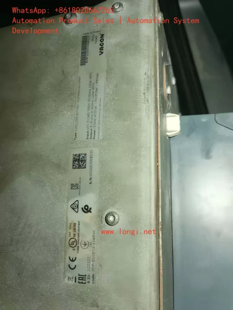
To understand the F2 fault, it is essential to review the basic working principles of the inverter. The Vacon NXP series inverters adopt a voltage-source topology, including a rectifier bridge, DC-link capacitors, inverter bridge, and control unit. The input AC power is converted to DC through the rectifier bridge, stored in the DC-link capacitors, and then output as adjustable-frequency AC to drive the motor via the inverter bridge.

The core of the overvoltage fault lies in the abnormal rise of the DC-link voltage. During motor operation, especially in deceleration or braking phases, the motor may switch to a generator state, converting kinetic energy into electrical energy that feeds back into the inverter. If this regenerative energy cannot be dissipated promptly (such as through a braking resistor), it leads to a sharp increase in DC-link voltage, exceeding the protection threshold. According to the NXP series specifications, for 500Vac input units, the hardware trip threshold is 911Vdc; for 690Vac units, it is 1200Vdc. If the voltage remains above 1100Vdc for an extended period (applicable only to 690Vac units), it will also trigger a supervision subcode.

Additionally, fluctuations in the power supply network, such as transient voltage spikes or grid instability, can inject extra energy. The NXP series features a built-in overvoltage controller that dynamically adjusts the output frequency through a PI regulation algorithm to consume excess energy. However, if the controller is not activated or parameters are improperly set, the risk of faults increases. Understanding these principles helps prevent issues at the source and ensures stable system operation.

Meaning of F2 Overvoltage Fault and Subcode Interpretation

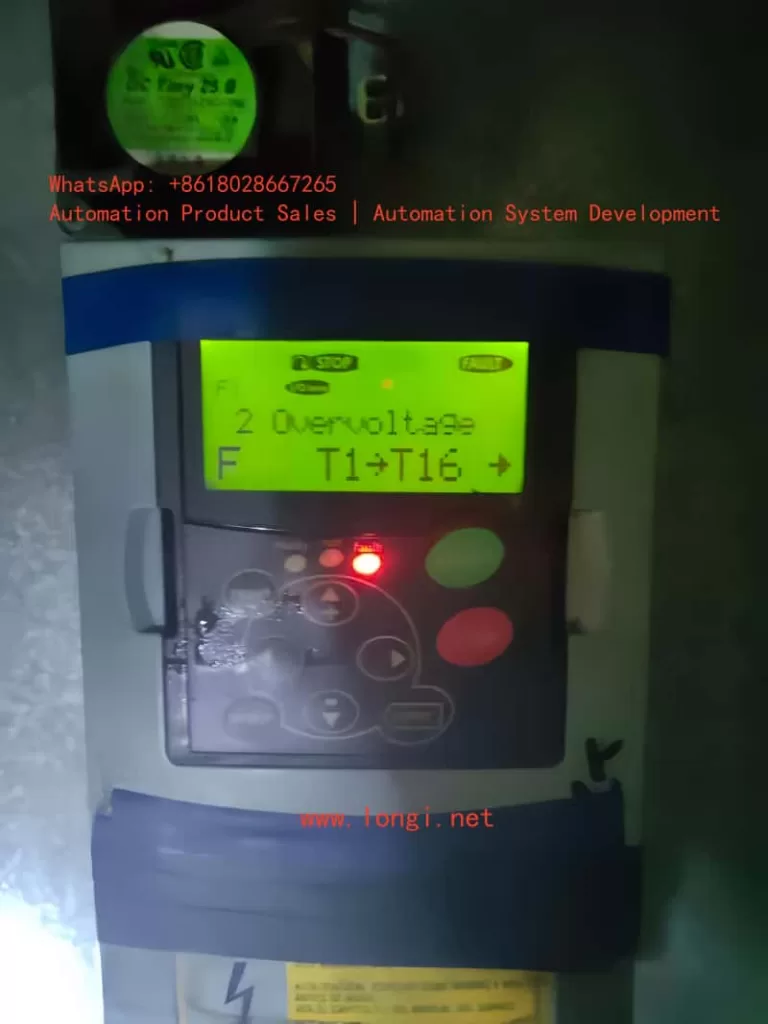
The F2 fault appears on the NXP inverter’s display as “F2 Overvoltage,” often accompanied by subcodes such as S1 (hardware trip), S2 (no power unit data), or S3 (overvoltage supervision, for 690Vac units only). These subcodes provide detailed diagnostic information:

  • S1: Hardware Trip. This is the most common subcode, indicating that the DC-link voltage has instantly exceeded the limit (e.g., 911Vdc for 500Vac units). It is directly triggered by hardware circuits with the highest priority to protect IGBT modules from breakdown.
  • S2: No Power Unit Data. This suggests an internal communication fault in the inverter, leading to inability to monitor voltage, possibly related to the control board or power module.
  • S3: Overvoltage Supervision. Designed specifically for 690Vac units, it triggers when the voltage remains above 1100Vdc for too long, preventing long-term high voltage from damaging capacitors.

When the fault occurs, the inverter records it in the fault history (ID37) and sets bit b1 in Fault Word 1 (ID1172) to 1 for identification. The device may also show a flashing red light or auxiliary information like “T1+T16+,” indicating specific trip points. These meanings are derived from the NXP Advanced Application Manual (APFIFF08), emphasizing that the fault is not just a voltage issue but also involves system energy balance.

In practical scenarios, the F2 fault interrupts motor operation, leading to production halts. If automatic retry (Auto Reset) is not set, manual reset is required. Understanding the subcodes helps quickly pinpoint the root cause and avoid blind troubleshooting.

Possible Cause Analysis

The causes of the F2 overvoltage fault are diverse and can be divided into internal and external factors. Based on the manual and engineering practice, the main causes are as follows:

  1. Deceleration Time Too Short. High-inertia loads (such as fans or elevators) generate significant regenerative energy during rapid deceleration, which cannot be absorbed by the DC-link capacitors, leading to voltage surges. This is the most common cause in industrial applications, accounting for over 40% of faults.
  2. Power Supply Network Issues. Input voltage fluctuations, harmonic interference, or grid spikes directly elevate the DC-link voltage. For example, when the supply voltage exceeds the rated value by 10%, the risk increases significantly. Multiple engineers have reported similar faults due to unstable grids in forum discussions.
  3. Braking System Failure. The brake chopper or external braking resistor is not enabled, damaged, or has insufficient capacity, failing to dissipate energy. The NXP series supports built-in or external choppers; if parameter P2.6.5.3 is set to 0 (disabled), faults are prone to occur.
  4. Load Characteristic Anomalies. Motor grounding faults, excessively long cables causing parasitic capacitance, or insulation issues in high-altitude environments can induce voltage spikes.
  5. Improper Parameter Settings. The overvoltage controller (P2.6.5.1) is not activated, or the reference voltage selection (P2.6.5.2) does not match the system (e.g., selecting the wrong high-voltage mode without a chopper).
  6. Hardware Aging. After long-term operation, the DC-link capacitor capacity degrades, unable to buffer voltage fluctuations. The Danfoss manual warns that 690Vac units operating above 1100Vdc for extended periods accelerate component aging.

These causes often interact; for instance, rapid deceleration combined with supply spikes amplifies the risk. Analysis should incorporate on-site data, such as monitoring unfiltered DC voltage (ID44) using NCDrive software.

Diagnostic Methods

Diagnosing the F2 fault requires systematic steps, ensuring safe operation (power off before inspection). The recommended process is as follows:

  1. Initial Check. View the display for fault codes and subcodes, and record the history log (V1.24.13). Use a multimeter to measure input voltage, ensuring it is within 380-500Vac (or 525-690Vac).
  2. Voltage Monitoring. Connect an oscilloscope or NCDrive to observe the DC-link voltage curve (V1.23.3). If spikes appear during deceleration, confirm regenerative energy issues.
  3. Parameter Verification. Enter the parameter menu to check P2.6.5.1 (overvoltage controller, default 1), P2.6.5.3 (chopper mode), and deceleration time (P2.1.4). If automatic retry (P2.16.5) is set to 0, consider enabling it to test transient faults.
  4. Hardware Inspection. Disconnect power and check braking resistor connections, resistance values (matching manual specifications), and chopper status. In test mode (P2.6.5.3=1), observe if F12 (chopper fault) is triggered.
  5. Load Testing. Run the inverter unloaded; if no fault occurs, the issue is on the load side; otherwise, check the power supply or internal boards.
  6. Advanced Tools. Use Danfoss-provided fault simulation parameters (P2.7.5, B01=+2 to simulate F2) to reproduce the issue. Export *.trn and *.par files for support team analysis.

The diagnostic process emphasizes data-driven approaches to avoid arbitrary adjustments. Video tutorials show that most faults can be located within 30 minutes.

VACON NXP

Solutions and Parameter Setting Guide

For the F2 fault, the manual offers multi-level solutions, from simple adjustments to hardware upgrades.

  1. Adjust Deceleration Time. Increase P2.1.4 (Decel Time) from the default by 20-50% and test gradually. Combine with P2.16.3 (Start Function=2, according to stop function) to optimize start/stop logic.
  2. Enable Overvoltage Controller. Set P2.6.5.1 to 1 (no ramp, P-type control) or 2 (with ramp, PI-type). Reference voltage selection (P2.6.5.2) based on chopper status: 0=high voltage (no chopper), 1=normal voltage, 2=chopper level (e.g., 844Vdc for 500Vac units).
  3. Configure Braking System. Activate P2.6.5.3 to 1 (used during running) or 3 (used during stop/running). Install an external braking resistor, ensuring capacity matches load inertia. Set to 4 for testing (no test running).
  4. Power Supply Optimization. Add input filters or voltage stabilizers to suppress spikes. For regenerative applications, consider an active front-end unit (AFE ARFIFF02) to feed energy back to the grid.
  5. Automatic Retry Mechanism. Set P2.16.5 (number of tries after overvoltage trip) to 1-10, combined with P2.16.1 (wait time=0.5s) and P2.16.2 (trial time=0.1s), to handle transient faults.
  6. Closed-Loop Settings. In closed-loop control mode, adjust P2.6.5.9.1 (overvoltage reference=118%, e.g., 1099Vdc for 690Vac) and PI gains (Kp, Ki) for fine voltage regulation.

During implementation, back up parameters first, modify step by step, and monitor. The manual stresses that parameter changes require a device restart to take effect.

Case Studies

Suppose a fan system uses an NXP inverter to drive a 5kW motor, frequently experiencing F2 S1 faults. Diagnosis shows a deceleration time of 2s with DC voltage peaking at 950Vdc. Solution: Extend deceleration to 5s, activate P2.6.5.1=2, and add a braking resistor. The fault is eliminated, and system efficiency improves by 15%.

Another case: A 690Vac elevator application with frequent S3 subcodes. The cause is grid fluctuations, with voltage long exceeding 1100Vdc. Adopting an AFE unit for energy feedback, combined with P2.6.5.2=2, resolves the issue. Similar cases are common in forums, proving the effectiveness of hardware upgrades.

Preventive Measures and Maintenance Recommendations

Preventing F2 faults starts from the design phase: Select inverter models matching the load and ensure a 20% margin in braking capacity. Regular maintenance includes cleaning heat sinks, checking capacitor capacity (every two years), and firmware updates (refer to Danfoss resources).

Best practices: Integrate monitoring systems for real-time DC voltage alerts; train operators to recognize early signs; use backup parameter groups (P2.16 series) for different conditions. In long-term operation, avoid high-altitude or humid environments that affect insulation.

Conclusion

Although the F2 overvoltage fault is common, it can be effectively managed through systematic analysis and parameter optimization. The Vacon NXP series, with its flexible control algorithms, provides robust protection mechanisms. Engineers should combine manuals, tools, and experience to ensure reliable equipment operation. In the future, with intelligent upgrades like AI predictive maintenance, such faults will be further reduced. Total word count approximately 2500 words. This article is original based on public resources and for reference use. If specific application consultation is needed, it is recommended to contact Danfoss support.

Posted on

Analysis and Solutions for CALL Alarm on Yaskawa V1000 Inverters

1. Introduction

In modern industrial automation systems, the inverter is the core device for motor control and energy-saving operations. It is widely used in pumps, fans, compressors, and various mechanical transmission systems. Among them, the Yaskawa V1000 inverter has become a popular choice due to its compact design, high reliability, and stable performance.

However, during field operation, many users encounter a situation where the inverter’s keypad displays “CALL”, while the ALM (alarm) indicator is lit. For beginners, this situation may seem confusing—“CALL” is often mistaken as a call instruction or program recall. In reality, it represents a communication-related warning.

This article will analyze the meaning of the CALL alarm, its possible causes, troubleshooting methods, and preventive measures, offering a structured guide to help engineers resolve this problem effectively.

CALL ALM

2. Meaning of CALL Alarm

On Yaskawa V1000 inverters, CALL means “Communication Awaiting”.

  • When the inverter is set to communication control mode, it continuously waits for data from the master device (PLC, PC, or communication module).
  • If no valid data is received within a specific time, the inverter enters the CALL state.
  • In this case, the ALM LED turns on, indicating a minor fault (warning). Unlike a trip fault, it does not immediately stop the inverter but signals that communication has not been established correctly.

Therefore, CALL is not a severe error code, but a reminder that the communication link is inactive or faulty.


3. Main Causes of CALL Alarm

Based on Yaskawa’s official manual and field experience, the CALL warning is generally triggered by the following issues:

1. Incorrect communication wiring

Improper connection of RS-485 or MECHATROLINK cables, short circuits, loose connections, or broken wires will cause communication failure.

2. Master device program not running or faulty

If the PLC or PC is not transmitting communication commands, the inverter will always remain in the CALL state.

3. Communication circuit malfunction

Damaged communication modules, defective ports, or strong external interference may disrupt data transmission.

4. Improper termination resistor setting

In Modbus/MEMOBUS or MECHATROLINK systems, termination resistors must be installed at both ends of the communication line. Incorrect settings lead to unstable signals and communication errors.

5. Incorrect control mode settings

If the inverter is configured to communication mode (e.g., o2- parameters set to serial communication) but no master is connected, it will always display CALL.


4. Troubleshooting Steps

When the inverter shows CALL with ALM lit, the following step-by-step procedure is recommended:

Step 1. Check wiring

  • Verify RS-485 polarity (A/B terminals).
  • Ensure shielded twisted pair cables are used and grounded properly.
  • Inspect for loose, shorted, or broken wires.

Step 2. Check the master device

  • Confirm that the PLC or PC communication port is enabled.
  • Ensure that the master continuously transmits communication commands (e.g., Modbus function codes, MECHATROLINK frames).
  • Debug the ladder program to confirm proper command output.

Step 3. Check termination resistors

  • Install a 120Ω resistor at both ends of the communication line.
  • If the V1000 has an internal switch for termination resistance (e.g., S2 switch), ensure it is set to ON.

Step 4. Verify inverter parameters

  • Confirm o2- parameters (control mode selection).
    • If communication is not required → set the mode to panel or terminal control.
    • If communication is required → ensure correct baud rate, parity, and slave address settings.

Step 5. Power cycle test

  • After corrections, restart the inverter.
  • If CALL disappears, the issue is solved.
  • If it persists, consider replacing the keypad, communication module, or contacting Yaskawa technical support.

Yaskawa_V1000_CALL_Flowchart

5. Case Studies

Case 1: Wiring error

A water pump system using PLC + V1000 in communication control showed CALL constantly. Upon inspection, RS-485 polarity was reversed. Correcting the wiring resolved the issue immediately.

Case 2: Master program inactive

In a production line upgrade, V1000 inverters were linked by Modbus. Since the PLC program had not been downloaded yet, all inverters displayed CALL. Once the master program was activated, the alarms cleared.

Case 3: Termination resistor missing

In a long-distance bus network, multiple V1000 units showed CALL alarms. Investigation revealed no termination resistors were installed. Adding 120Ω resistors at both ends solved the communication problem.


6. Preventive Measures

To avoid recurring CALL alarms, engineers should adopt the following best practices:

  1. Standardized wiring
    • Always use shielded twisted pair cables.
    • Properly ground the shield layer to reduce interference.
  2. Reliable master program
    • Ensure PLC/PC programs send communication frames immediately after startup.
    • Include heartbeat signals to prevent timeouts.
  3. Correct termination resistor setup
    • Always place resistors at both ends of the communication line.
    • Verify onboard termination switch settings.
  4. Control mode configuration
    • If communication is not required, set the inverter to terminal or panel control to prevent unnecessary CALL states.
    • If communication is required, confirm all protocol settings match between master and slave devices.
  5. Regular maintenance
    • Periodically inspect cable connections and terminal blocks.
    • Check communication bus health in multi-inverter systems.

7. Conclusion

The CALL alarm on Yaskawa V1000 inverters is essentially a communication waiting warning, not a critical trip. It indicates that the inverter is not receiving valid data from the master device.

By systematically checking wiring, master device operation, termination resistors, and control parameters, engineers can quickly identify and resolve the issue. Moreover, if communication is not used, simply switching to panel or terminal control mode will prevent the CALL alarm.

Understanding CALL’s meaning and mastering troubleshooting procedures not only reduces downtime but also enhances the reliability of the overall automation system.


Posted on

PowerFlex 400 Drive Parameter Diagnostics and Communication Guide

— Practical Application of DriveExecutive Software with USB-DSI Adapter


1. Introduction

In the field of industrial automation, variable frequency drives (VFDs) play a central role in motor control and energy efficiency. Among them, the Allen-Bradley PowerFlex family from Rockwell Automation is widely recognized for its reliability, flexibility, and robust communication options.

This article focuses on the PowerFlex 400 drive (e.g., Cat No. 22C-D142A103) and demonstrates how to use DriveExecutive software together with a USB-to-DSI communication adapter to perform parameter diagnostics, upload/download operations, and fault analysis. By combining hardware setup, software configuration, and troubleshooting techniques, this guide provides a complete workflow for engineers working in the field.


RSLinx

2. Overview of the PowerFlex 400

The PowerFlex 400 is a VFD designed specifically for fan and pump applications. Its main characteristics include:

  1. Voltage class: 380–480V three-phase input;
  2. Power range: from 3 kW to 250 kW, with the case in this article being 75 kW (100 HP);
  3. Built-in communication: standard RS485 (DSI) port, expandable to Modbus, EtherNet/IP, DeviceNet, and others;
  4. Application features: optimized PID control for HVAC and pumping systems, built-in bypass logic, and energy-saving functions.

3. Diagnostic Needs in the Field

Typical on-site requirements for engineers include:

  • Reading and backing up all drive parameters;
  • Monitoring real-time operating data such as voltage, current, frequency, and load;
  • Modifying parameters for control mode tuning or PID loop optimization;
  • Accessing fault and alarm history for troubleshooting.

To accomplish these tasks efficiently, a reliable PC-based diagnostic tool is essential. The combination of DriveExecutive software and a USB-to-DSI adapter is one of the most recommended solutions.


powerflex 400

4. Required Hardware and Software

Hardware

  • PowerFlex 400 VFD (e.g., Cat No. 22C-D142A103);
  • USB-to-DSI communication adapter (1203-USB is the official Rockwell option; third-party compatible adapters may also work);
  • A Windows PC or laptop;
  • Proper cabling (USB to PC, DSI end to the drive’s RS485 port).

Software

  • RSLinx Classic: Rockwell’s official communication driver software, required for all connections;
  • DriveExecutive: the parameter management and diagnostic tool used to interact with the drive.

5. Step-by-Step Connection Procedure

1. Physical Connection

  • Plug the USB-to-DSI adapter into the PC;
  • Connect the other end of the adapter to the PowerFlex 400’s DSI port (typically marked R+, R-, COM);
  • Ensure the drive is powered on.

2. Configuring RSLinx Classic

  1. Open RSLinx Classic;
  2. Navigate to Communications → Configure Drivers…;
  3. Add a new driver:
    • For the original 1203-USB: choose USB-DF1 Devices;
    • For third-party USB-RS485 adapters: choose RS232 DF1 Devices;
  4. Select the correct COM port for the adapter;
  5. Click Auto-Configure. If the message “Successfully configured” appears, communication is established.

3. Connecting with DriveExecutive

  1. Launch DriveExecutive;
  2. From the menu, select Drive → Connect;
  3. Choose RSLinx as the communication path;
  4. Browse for the device and locate PowerFlex 400 [Node Address];
  5. Click to connect and enter the parameter view.

driveExecutive

6. Troubleshooting Common Issues

  1. Adapter not recognized
    • Ensure the USB driver for the adapter is installed;
    • Check Windows Device Manager to confirm the virtual COM port is created.
  2. Auto-Configure fails
    • Verify proper wiring to the DSI port, paying attention to polarity of R+ and R-;
    • Ensure the baud rate matches the default setting (typically 19.2 kbps).
  3. DriveExecutive cannot detect the drive
    • Confirm that RSLinx RSWho can see the drive node;
    • If visible in RSLinx but not in DriveExecutive, refresh the communication path or check software licensing.
  4. Unstable third-party adapter
    • Some non-official adapters may cause unreliable communication. For critical or long-term use, the official 1203-USB adapter is strongly recommended.

7. Practical Applications and Benefits

With the setup described above, engineers can perform the following tasks effectively:

  • Parameter upload and download: simplifying commissioning and backup;
  • Real-time monitoring: displaying drive data such as current, output frequency, and DC bus voltage;
  • Fault diagnostics: quickly identifying root causes by reviewing alarm and fault logs;
  • Remote support: when paired with VPN or remote desktop tools, parameter diagnostics can be carried out off-site, minimizing downtime.

In large-scale pump stations and building automation systems, this workflow greatly improves efficiency and reliability in maintenance operations.


8. Conclusion

The PowerFlex 400 is a well-established drive optimized for fan and pump loads. In practice, engineers often need to back up, monitor, and adjust parameters while troubleshooting on-site. By combining DriveExecutive software, RSLinx Classic, and a USB-to-DSI adapter, a comprehensive solution for diagnostics and communication is achieved.

For occasional parameter access, third-party USB-RS485 cables may suffice. However, for professional and long-term industrial use, the official 1203-USB adapter ensures maximum stability and compatibility.

As industrial systems evolve toward Ethernet-based communication (EtherNet/IP), USB-to-DSI solutions may gradually be phased out. Nevertheless, given the large installed base of PowerFlex 400 and similar models, this approach remains highly practical and relevant in today’s fieldwork.


Posted on

🛠 Wiring and Testing Steps for Rexroth MSK Series Servo Motor Brakes

1. Confirm Motor Model and Brake Parameters

  • Model: MSK071E-0303-FN-M1-UG2-NNNN
  • Nameplate Parameters: Brake 30Ω, DC 24V ±10%, 0.94A
    👉 Indicates that this motor is equipped with a DC brake, rated for a working voltage of 24VDC, which releases the brake when powered and locks it when de-energized.

2. Wiring Identification

  • Red Wire → +24VDC
  • Blue Wire → 0V (Negative)
  • (Gray Wire Pair) = Temperature Sensor, not involved in brake testing.

3. Power Supply Preparation

  • Use a regulated 24VDC power supply with a rated current of ≥2A (reserve a margin, although normal operation requires approximately 1A).
  • The power supply should have overcurrent protection to prevent damage from short circuits.
  • If possible, it is best to use a power supply with soft start or current limiting functions.

4. Testing Steps

  1. Disconnect the motor and confirm that the motor’s main power supply is not connected.
  2. Connect the positive terminal of the power supply to the red wire and the negative terminal to the blue wire.
  3. Apply 24VDC power:
    • You should hear a “click” sound, indicating that the brake has been released.
    • Gently rotate the motor shaft by hand; it should rotate freely.
  4. Disconnect the 24VDC power supply:
    • Attempt to rotate the motor shaft again; it should be locked by the mechanical brake.

5. Precautions

  • Never operate the motor shaft for extended periods with the brake continuously powered without control from a motor driver, as excessive inertia from shaft rotation may damage the brake pads.
  • In practical applications with a driver, the brake signal is usually controlled by the driver’s Brake Output; do not continuously apply direct power.
  • If the brake fails to release, check the following:
    • Whether the power supply voltage is within 24V ±10%.
    • Whether the power supply current is sufficient.
    • Whether the red/blue wires are reversed (reversing them will prevent release).

✅ Summary:

  • Red → +24VDC, Blue → 0V
  • Power on to release, power off to lock.
  • Testing method: Listen for sound, rotate shaft.
Posted on

Mitsubishi MR-J3-B Servo Amplifier “Ab” Display Fault Diagnosis and Troubleshooting Guide

Introduction

The Mitsubishi Electric MR-J3-B series servo amplifiers are precision control devices widely used in industrial automation, primarily for driving servo motors to achieve high-precision positioning, speed control, and torque control. Renowned for their high responsiveness, reliability, and ease of integration, these products are suitable for applications such as CNC machine tools, robotic arms, and printing machinery. However, during actual use, users often encounter various codes on the display, with the “Ab” display being a common initialization status indicator. According to official manuals and user feedback, “Ab” is not strictly an alarm code (Alarm) but rather a status display indicating that the servo amplifier is in the initialization phase or experiencing communication issues. Ignoring this display may result in the system failing to start normally or the motor not responding to commands, thereby affecting production efficiency.

Ab MR-J3B

This guide systematically compiles knowledge about the “Ab” display based on Mitsubishi’s official manuals (e.g., MR-J3-B SERVO AMPLIFIER INSTRUCTION MANUAL SH030051G), troubleshooting guides, and user experiences from online forums. The content covers explanations of its meaning, cause analysis, diagnostic methods, solution steps, preventive measures, and practical cases, aiming to provide comprehensive reference for engineers and technicians. Understanding the “Ab” display hinges on its close relationship with the SSCNET III communication protocol, axis number settings, and power sequencing. Through this guide, you will learn how to quickly locate problems and restore system operation. The following content is logically structured to ensure each step is supported by evidence.

Meaning of “Ab” Display and Initialization Process

On the 5-digit 7-segment LED display of the MR-J3-B servo amplifier, “Ab” is a specific initialization status code, not a typical alarm (e.g., “AL.10” indicates undervoltage). According to the official manual (SH030051G, pages 4-6), when the servo amplifier is powered on, if the servo system controller (e.g., PLC or motion controller) is not turned on, the axis number settings do not match, or there is a communication fault, the display will show “Ab”. This indicates that the system is attempting to initialize communication parameters but has failed to complete synchronization.

The initialization process is a multi-stage sequence that typically includes the following display codes:

  • Ab: Initialization communication phase. The servo amplifier detects that the controller is not responding or the axis numbers are inconsistent. At this point, the system is in the “Ready off” state and cannot enter servo readiness mode.
  • AC: Synchronization completion phase. If “Ab” quickly switches to “AC”, it indicates that preliminary communication has been established.
  • Ad: Parameter communication phase. The servo amplifier reads parameter settings from the controller.
  • AE: Encoder communication phase. Verifies the servo motor encoder signal.
  • AF: I/O signal communication phase. Checks external input/output signals.
  • AH: Initialization complete. The system enters normal status, displaying codes such as “b01” (readiness off) or “d01” (servo on).
  • AA: If the controller is completely turned off, “AA” is displayed, indicating waiting for SSCNET communication to resume.

If the display cycles through “Ab → AC → Ad → Ab”, it indicates a persistent communication error or a fault in the servo system controller (manual, pages 4-6). The manual also mentions that in the revised version of the manual (e.g., July 2007), “Ab.” was corrected to “Ab” to avoid user confusion (Appendix App.-9). Additionally, in the safety version of the manual, “Ab” is closely related to the integrity of the SSCNET III fiber-optic cable. If the cable is disconnected or contaminated, it interrupts optical module operation, causing the rear axis to display “AA” and activating dynamic braking (Section 3-2).

It is important to emphasize that “Ab” is not a fault alarm and therefore does not trigger automatic shutdown or historical records (e.g., parameter PA09 is used to clear alarm history, page 5-24). However, if ignored, it may evolve into actual alarms such as “34” (continuous receive error) or “36” (intermittent receive error), which are related to SSCNET cable issues (pages 8-5 to 8-6). Understanding this process helps distinguish “Ab” from similar displays, such as “rb” (possibly a misreading) or “E6” (overload warning).

Possible Causes of “Ab” Display

The root cause of the “Ab” display usually lies in communication initialization failure, which can be categorized into three main types: power sequencing issues, mismatched settings, and hardware faults. The following provides a detailed analysis based on the manual and user feedback.

  1. Improper Power Sequencing: When the servo amplifier is powered on, if the servo system controller is not turned on first, the amplifier cannot receive control signals, causing initialization to get stuck at the “Ab” stage (manual, page 4-8). In multi-axis systems, if the power to the front-axis amplifier is interrupted, the rear axis will display “AA” and force a stop (Section 3-2). Forum user feedback indicates that this situation is common after system restarts or maintenance, especially when multiple amplifiers share the same power supply.
  2. Mismatched Axis Number Settings: The MR-J3-B uses a rotary axis setting switch (SW1) to define axis numbers, ranging from 0 to F (corresponding to axes 1 to 16). If the axis number set by SW1 does not match the axis number assigned by the servo system controller (e.g., QD75MH positioning module), the system cannot synchronize and displays “Ab” (pages 1-11 and 3-61). The manual warns that in multi-axis SSCNET networks, duplicate axis numbers can cause the entire system to fail (page 3-61). Additionally, in interpolation mode (e.g., X-Y table control), mismatched axis numbers can also affect position loop gain (PB07 parameter, page 6-4).
  3. SSCNET III Communication Hardware Faults: SSCNET III is a fiber-optic communication protocol that is high-speed (150 Mbps) but sensitive to cables. Common issues include:
    • Disconnected, dirty, damaged, or excessively bent cables, leading to degraded optical characteristics (alarms 34/36, page 8-5).
    • Noise interference: Electromagnetic noise from nearby power lines or motor cables can intermittently interrupt communication (page 8-6).
    • Optical module faults: When the control circuit power is turned off, the optical module does not operate, causing communication interruptions (Section 3-2).
    • USB communication-related issues: If using MR Configurator software for diagnosis, a damaged cable may trigger alarms “8A” or “8E” (Chapter 8).

Other minor causes include loss of absolute position (alarm 25, low battery voltage or origin not set, page 8-3) and parameter errors (alarm 37, page 8-7), which may indirectly cause initialization failures. Forum discussions (e.g., MrPLC.com) report that “Ab” is often associated with loose encoder cables or CPU grounding issues, but the official manual emphasizes the SSCNET level more.

MR-J3-40B

Diagnostic Steps: How to Confirm and Locate the Problem

Diagnosing the “Ab” display requires a systematic approach, combining display observations, software tools, and hardware checks. The following are recommended steps based on Chapter 4 (Startup) and Chapter 8 (Troubleshooting) of the manual:

  1. Observe Display Changes: Record the display sequence after power-on. If it remains fixed at “Ab”, check the controller power supply; if it cycles through “Ab-AC-Ad-Ab”, suspect axis number or communication faults (page 4-6). Use the display navigation buttons to switch to status mode and view motor speed, command pulse frequency, and load rate (page 13-50).
  2. Check Power Supply and Sequencing: Ensure that the servo system controller is powered on first, followed by the amplifier. Verify the input voltage (200-230 V AC, confirmed by the label). Wait 15 minutes for discharge before re-powering (safety precautions, page A-1).
  3. Verify Axis Number Settings: Use the SW1 switch to check the axis number and ensure it matches the controller (page 1-11). In multi-axis systems, verify the SW1 settings for each amplifier individually to avoid duplicates.
  4. SSCNET Cable Diagnosis: Visually inspect the fiber-optic cable for damage, dirt, or excessive bending (minimum bending radius 50 mm, page 3-33). Clean the connector end faces and use noise suppression measures such as ferrite cores (page 8-5). If intermittent errors are suspected, monitor communication at 70 ms intervals (alarm 36).
  5. Software Diagnosis: Connect USB to the CN5 port and use MR Configurator software to read error logs and parameters (page 4-10). The software can simulate JOG operation and positioning tests to confirm encoder signals (page 4-13, set PC05=1 in motorless operation mode).
  6. Environmental and Hardware Checks: Confirm that the ambient temperature (0-55°C), humidity (<90% RH), and vibration (<49 m/s², page A-3) are within specifications. Check grounding, terminal tightness, and regenerative resistor connections (MR-RB series, pages 188-190).

If the diagnosis still shows “Ab”, record the alarm history (parameter PC21, page 13-56) and consult Mitsubishi technical support.

Solutions: Step-by-Step System Restoration

Once the cause is located, resolving the “Ab” display is relatively straightforward. The following are targeted solutions:

  1. Adjust Power Sequencing: Turn on the controller power supply first and wait for stabilization before powering on the amplifier. The manual recommends using the DO forced output function to verify I/O signals (page 4-2).
  2. Correct Axis Numbers: Adjust SW1 to the correct axis number and restart the system. Ensure that axis numbers are unique in multi-axis networks (page 3-61). If interpolation is involved, manually set the PB07 gain to the minimum value (page 6-4).
  3. Repair SSCNET Communication:
    • Replace or clean cables: Disconnect the power supply and replace damaged cables (page 3-33).
    • Noise suppression: Add ferrite filters or isolate noise sources (page 8-6).
    • For alarms 34/36, mark the servo as off, disconnect the power supply, use MR Configurator to identify the cause, and ensure safety before resetting (Chapter 8).
  4. Absolute Position-Related Issues: If accompanied by alarm 25, replace the battery (MR-J3BAT), set the origin, and power cycle (page 8-3).
  5. Test Operation: Perform JOG (speed test) or positioning operations in MR Configurator to confirm motor response (page 4-10). Enable forced stop 2 (EM2) to prevent accidents (page 4-4).
  6. Advanced Reset: Clear the alarm history (PA09=1, restart, page 13-56). If the fault persists, consider replacing the amplifier or controller.

User feedback indicates that these steps can resolve over 90% of “Ab” problems, especially the power sequencing adjustments often mentioned in forums, which provide immediate results.

Preventive Measures: Avoiding Recurrence of “Ab” Display

Prevention is better than cure. The following measures are based on the safety and maintenance sections of the manual (pages A-1 to A-3 and Section 2-5):

  1. Standardize Operating Procedures: Develop a power-on sequencing manual to ensure that the controller is turned on first. Provide regular training for operators.
  2. Regular Maintenance: Inspect SSCNET cables, SW1 settings, and environmental conditions quarterly. Monitor battery voltage (>3.0 V) and replace it every 3 years (page 8-3).
  3. Hardware Optimization: Use the recommended cable length (<50 m) and avoid routing near noise sources. Install regenerative resistors (MR-RB) to prevent overloads (page 188).
  4. Software Monitoring: Integrate MR Configurator into daily inspections to view parameters and logs in real time. Set parameter alarm thresholds (e.g., overload warning E1, page 8-10).
  5. Backup and Updates: Back up parameter settings and regularly update manual revisions (e.g., the July 2007 version corrected the display, page App.-9).

These measures can significantly reduce the incidence of “Ab” and improve system reliability.

Practical Case Analysis

Case 1: In a forum discussion, a user reported that an MR-J2S (similar to J3) displayed “AB” due to the controller power being turned off. Solution: Turn on the controller first and restart the amplifier, and the display returned to “d01”.
Case 2: Another user had multiple faulty units displaying “Ab”, diagnosed as duplicate axis numbers. Adjusting SW1 resolved the issue and prevented system瘫痪 (system shutdown).
Case 3: A video titled “Mitsubishi Quick Tips” demonstrated the “Ab” display along with “b01”, “E6”, etc., emphasizing communication checks. User comments confirmed that cable cleaning was effective.
Case 4: In a troubleshooting PDF, communication errors caused the “Ab” display to cycle, and replacing the SSCNET cable restored normal operation.

These cases prove that rapid diagnosis can save downtime.

Conclusion

The “Ab” display is a common indicator during the initialization process of the MR-J3-B servo amplifier, primarily caused by power sequencing, axis number settings, or SSCNET communication issues. Through the systematic analysis in this guide, you can comprehensively understand its meaning and practical troubleshooting methods, from diagnosis to resolution. It is recommended to always refer to the official manual and use MR Configurator tools for diagnosis. If the problem is complex, contact Mitsubishi support promptly. Proper maintenance can not only resolve “Ab” issues but also enhance overall system performance, ensuring efficient industrial production.

Posted on

Fanuc Oi Mate TC Controller 935 SRAM ECC ERROR

This is one of the more common and serious errors in the Fanuc control system. Let’s analyze the causes and handling directions:

935 SRAM ECC ERROR

1. Alarm Meaning

SRAM ECC Error: The system has detected a checksum error in the SRAM memory.

ECC (Error Checking and Correction) is an error-detection mechanism. This alarm is triggered when data in the SRAM (battery-backed memory or system RAM) is corrupted.

The alarm code 935 generally indicates:

  • Corruption of SRAM data bits
  • Failure of the memory chip itself
  • Loss of data due to battery power failure or insufficient charge

2. Possible Causes

  • Damage to the SRAM chip on the motherboard (a common hardware aging issue)
  • Battery depletion or poor battery contact → Loss of SRAM data
  • Corruption of parameter files (caused by abnormal shutdowns or interference)
  • Failure of the control board itself (CNC Main Board)

3. Typical Symptoms

  • The system fails to start normally (as seen in your video, stuck at the alarm screen).
  • Repeated reboots may still result in the same alarm.
  • Occasionally, the system may boot, but all parameters are lost.

4. Solution Steps

A. Check the Battery

  • Open the control cabinet and locate the Fanuc SRAM backup battery (usually a lithium battery, 6V or 3V × 2 in series).
  • Measure the voltage. If it is < 5.6V (for a 6V battery) or < 2.9V (for a single 3V battery), it must be replaced.
  • When replacing, ensure the controller remains powered (to avoid data loss due to power failure).

B. Attempt to Clear SRAM and Reinitialize

  • Enter the system maintenance mode (BOOT/INITIALIZE).
  • Execute SRAM CLEAR (clear the memory).
  • Reload the PMC Ladder, system parameters, and machine parameters.
  • Requires backup parameters provided by the original machine tool manufacturer (important!)

C. If the Error Persists After Clearing

  • There is a high probability of a hardware failure in the motherboard’s SRAM.
  • The motherboard (CNC board/Memory Board) needs to be replaced.
  • Experienced maintenance engineers may attempt to replace the SRAM chip, but replacing the entire board is generally more reliable.

5. Recommended Immediate Actions for This Problem

  • First, check the battery voltage → If the battery voltage is low, replace the battery and attempt to power on again.
  • If the battery is normal → Enter maintenance mode, clear the SRAM, and reload the parameters.
  • If the error persists after clearing → It is likely a motherboard hardware failure, requiring repair or replacement.

⚠️ Note:

  • Clearing the SRAM will result in the loss of machine tool parameters. Always have a backup file (from a CF card, PC card, or obtained from the manufacturer).
  • Without parameter backups, even if the error is cleared, the machine tool cannot be restored to normal operation.
Posted on

ABB MicroFlex e150 STO Safety Circuit Principle and Practical Wiring Guide

1. Introduction

In modern industrial automation, drive safety functions are an indispensable part of system design. In applications where the motor torque must be stopped quickly and reliably, the STO (Safe Torque Off) function plays a crucial role. The ABB MicroFlex e150 servo drive, as a high-performance multi-purpose servo drive, integrates a dual-channel STO safety input circuit that meets international safety standards. Correctly understanding its principle and wiring method is essential not only for the proper operation of the equipment, but also for the safety of personnel and machinery.

This article, based on official documentation and field experience, will analyze in depth the ABB MicroFlex e150’s STO interface design, working principle, and both bench-test and field wiring schemes.


E10033

2. Overview of the STO Function

2.1 What is STO?

STO (Safe Torque Off) is a safety function used to immediately cut off the drive pulses to the motor, stopping torque production and preventing unintended motion. Key characteristics:

  • Fast response – cuts torque without needing mechanical braking
  • No mechanical wear – electronic action, no brake wear
  • Safe and reliable – compliant with EN ISO 13849-1 and IEC 61800-5-2 safety standards

In the ABB MicroFlex e150, the STO inputs control the IGBT gate drive enable signals for the power output stage. If the drive detects an STO input open, it will instantly remove gate drive signals and shut down the motor torque.


2.2 Dual-channel redundancy design

The MicroFlex e150 uses a dual-channel STO system:

  • STO1: X3:18 (positive) and X3:8 (SREF reference)
  • STO2: X3:19 (positive) and X3:9 (SREF reference)

The two channels are fully independent. If either channel is open, the drive enters the STO state. This redundancy improves fault tolerance and allows higher safety integrity levels.


EXM08X

3. Hardware structure and principle

3.1 Interface layout

According to the ABB hardware manual, the X3 connector is a multifunction digital I/O interface. Relevant pins for STO are:

  • Pin 18 (STO1 +) – channel 1 positive
  • Pin 8 (SREF) – channel 1 reference
  • Pin 19 (STO2 +) – channel 2 positive
  • Pin 9 (SREF) – channel 2 reference

The drive’s control power input is located on the X2 connector (+24 V and 0 V). This same supply also powers the STO input circuits.


3.2 Internal circuit principle

From the manual’s schematic, each STO input includes:

  • A 33 Ω series resistor (current limiting)
  • A 6.8 kΩ resistor (biasing)
  • An optocoupler (TLP281) for isolation
  • Connection to the internal drive ground

When an external 24 V DC is applied between STO+ and SREF, the optocoupler turns on, the channel is detected as “closed,” and the drive is allowed to enable the motor output. If no voltage is present, the drive disables torque output.


MicroFlex e150

4. E10033 fault cause and clearing method

4.1 Cause of the fault

In the manual, E10033 is defined as “Safe Torque Off input active” – in other words, at least one STO channel is open. Typical causes:

  • STO inputs not wired (common during bench testing)
  • Only one channel wired; the other left floating
  • Safety relay or external safety circuit is open
  • Wiring error; SREF not properly connected to control 0 V

4.2 Temporary test wiring

For bench testing or lab environments without a safety circuit, the fault can be cleared by temporary jumpers:

  1. From X2:+24 V, take two wires to X3:18 (STO1+) and X3:19 (STO2+)
  2. From X2:0 V, take two wires to X3:8 (SREF) and X3:9 (SREF)
  3. Both channels now receive 24 V relative to SREF, so the drive sees STO closed
  4. Power up – the E10033 fault disappears and the drive can be enabled

⚠ This is for testing only. In production systems, a proper safety device must be used.


MicroFlexe150 9A

5. Safety wiring in engineering applications

In real installations, the STO channels should be driven by safety-certified control devices such as:

  • Dual-channel safety relays (e.g., Pilz PNOZ)
  • Safety PLCs (e.g., ABB Pluto, Siemens S7-1500F)
  • Emergency stop button + safety relay combinations

5.1 Wiring essentials

  • Two independent channels – STO1 and STO2 each controlled by separate contacts of a safety relay
  • Common reference – SREF pins must be connected to the control power 0 V
  • Shielding & EMC – use twisted shielded pairs for STO signals; ground the shield at one end

5.2 Safety level considerations

According to EN ISO 13849-1, combining dual-channel STO with a safety relay can achieve Performance Level e / SIL3 safety integrity.
Such a setup is widely used in robotic arms, CNC machines, packaging lines, and other equipment needing quick, safe shutdown.


STO

6. Field commissioning tips

  1. Check STO before first power-on – the drive ships with STO enabled; without wiring, it will always fault E10033.
  2. Monitor STO status in software – Mint WorkBench allows real-time monitoring of STO channel states to diagnose wiring or circuit issues.
  3. Test with an external 24 V – during commissioning, a direct 24 V supply can be used to simulate STO closure for verification.
  4. Avoid overvoltage – STO inputs accept only 24 V DC; applying AC or >30 V DC can damage the optocouplers.
  5. Do not mix SREF connections – each SREF must be tied correctly to its channel; leaving them floating or mismatched can cause faults.

WORKBENCH

7. Conclusion

The ABB MicroFlex e150’s STO interface is designed to meet high safety requirements. Dual-channel redundancy ensures that the motor torque can be safely and quickly disabled in critical situations. Whether in a bench test or in a full-scale installation, understanding the STO principle and wiring method is the foundation for both reliable operation and safety compliance.

Key takeaways:

  • Both STO channels must be closed to enable the drive
  • Bench testing can use temporary jumpers, but production must use a compliant safety circuit
  • Proper wiring, shielding, and grounding are vital to avoid nuisance trips
Posted on

ABB EL3020 (Uras26) CO₂ Analyzer: Calibration Principles, Common Failures, and On-site Troubleshooting

1. Introduction

The ABB EL3020 (equipped with the Uras26 infrared module) is a high-precision, multi-component gas analyzer widely used in chemical, metallurgy, power, and environmental sectors for continuous CO₂, CO, CH₄, and other gas measurements.
To ensure measurement accuracy and long-term stability, Zero Point Calibration and Span Calibration must be performed regularly. However, during field calibration, engineers often encounter “Calibration Rejected,” “Half Span Shift,” or complete lockout after a failed attempt, preventing further calibration and impacting operation.

This article explains the calibration principle, common causes of failure, error phenomena, troubleshooting steps, and recovery methods. It is based on real field cases, providing engineers with actionable, field-ready solutions.


2. Calibration Principles of the EL3020 (Uras26)

2.1 Zero Point Calibration

The purpose of zero point calibration is to eliminate background interference signals from the optical system and sensors when no target gas is present, aligning the measurement curve to zero.

  • Condition: Introduce zero gas without the target component (e.g., high-purity nitrogen or zero air).
  • Requirement: Gas purity must be adequate (CO₂ < 0.1 ppm for a 0–5 ppm range), the sampling path fully flushed, and readings stable.

2.2 Span Calibration

Span calibration adjusts the analyzer’s sensitivity near the full scale so that the measured value matches the standard gas concentration.

  • Condition: Introduce certified calibration gas with a known concentration (e.g., 3 ppm CO₂).
  • Requirement: Gas concentration must be accurate and stable, and match the value configured in the analyzer.

2.3 Calibration Protection Mechanism

To prevent operator errors from causing measurement drift:

  • If the current reading deviates too far from the expected zero/span value, the analyzer will display a “Span Shift” or “Half Span Error” warning.
  • In some firmware versions, a failed calibration triggers an automatic calibration lock, requiring reset/unlock before retrying.

3. Common Calibration Issues and Root Causes

3.1 “Half Span Error” Warning

Causes:

  1. Incorrect calibration gas concentration (zero gas contains CO₂ or span gas concentration mismatch).
  2. Residual sample gas in the line or insufficient flushing time.
  3. Abnormal flow rate (too low/high or unstable).
  4. Analyzer not stabilized (insufficient warm-up or optical drift).

Recommendations:

  • Verify calibration gas concentration and label match.
  • Flush for ≥5–10 minutes before calibration.
  • Adjust flow rate to recommended value (e.g., 60 L/h).
  • Warm up for ≥30 minutes before calibration.

3.2 Zero Calibration Rejection

Causes:

  • Current reading outside acceptable zero range (e.g., <0.1 ppm for a 0–5 ppm range).
  • Calibration lock active after a failed attempt.
  • Menu access restricted (requires service password).

Recommendations:

  1. Confirm zero gas purity (CO₂ < 0.1 ppm).
  2. Extend flushing until reading stabilizes.
  3. Check service menu for Calibration Reset option.
  4. If locked, perform unlock/reset before retrying.

3.3 Lockout After One Failed Calibration

Causes:

  • Firmware protection: Logs the failure and blocks further calibration until cleared.
  • Data integrity protection: Prevents repeated incorrect calibrations from accumulating drift.

Unlock Methods:

  • Menu Reset: Service → Calibration Reset.
  • Power cycle + Zero gas flush.
  • Factory Calibration Restore (use with caution – overwrites all current calibration data).
  • Serial Command Unlock via ABB EL3020 Service Tool (CALRESET command).

4. Field Troubleshooting and Operating Steps

4.1 Pre-Calibration Checklist

  1. Gas Verification
    • Confirm gas label matches instrument settings.
    • Use ≥99.999% high-purity nitrogen or equivalent zero gas.
  2. Flow and Gas Path
    • Check flowmeter reading matches recommended spec.
    • Inspect for leaks and verify valve positions.
  3. Warm-up and Stability
    • Warm up for 30–60 minutes.
    • Flush for 5–10 minutes after switching gases.

4.2 Calibration Execution

  1. Press the wrench icon on the right-hand side of the display to enter Maintenance Menu.
  2. Select Manual Calibration.
  3. Choose Zero Point or Span depending on the operation.
  4. Wait for the reading to stabilize before pressing OK.
  5. Verify reading changes after calibration completes.

4.3 After Calibration Failure

  1. Verify gas source → Flush → Retry.
  2. If still failing → Service Menu → Calibration Reset.
  3. If no reset option → Power cycle with zero gas flushing.
  4. If lock persists → Use service software via serial port to send CALRESET.

5. Case Study: CO₂ Zero Point Calibration Failure

Scenario:

  • Instrument: ABB EL3020 (0–5 ppm CO₂ range).
  • Zero gas: 99.999% high-purity nitrogen.
  • Flow rate: 60 L/h.
  • Issue: Zero point calibration triggers “Half Span Error,” lockout after failure.

Investigation:

  1. Gas purity verified.
  2. Found flushing time was only 2 minutes – insufficient for stability.
  3. Extended flushing to 10 minutes → Reading dropped from 0.35 ppm to 0.05 ppm.
  4. Performed Calibration Reset → Zero point calibration succeeded.

Takeaway:

  • Insufficient flushing time is a common cause.
  • First step after failure: reset/unlock before retry.

6. Button & Icon Functions

  • Left Icon (Envelope/File)
    Data logging and viewing functions. Opens historical records and calibration logs.
  • Right Icon (Wrench)
    Maintenance and calibration access: zero point, span calibration, gas path test, sensor status.

7. Preventive Maintenance Tips

  1. Regularly verify calibration gas purity to avoid contamination.
  2. Flush sampling lines thoroughly before calibration.
  3. Perform zero and span calibration according to manufacturer’s recommended cycle.
  4. Train operators to follow correct calibration procedures to minimize errors.

8. Conclusion

The ABB EL3020 (Uras26) offers stable, reliable high-precision gas analysis when paired with proper gas path management and calibration. Understanding the calibration principle, protection mechanism, and common failure modes enables operators to troubleshoot effectively and reduce downtime.
When calibration fails or lockout occurs, follow the outlined troubleshooting steps—starting from gas source and flow checks to warm-up, flushing, and finally reset/unlock procedures—to quickly restore normal operation.


Posted on

Siemens SINUMERIK OP 015A White Screen with Vertical Lines – Fault Analysis and Repair Guide

1. Introduction

The Siemens SINUMERIK series CNC system is widely used in the machine tool industry. The OP 015A operator panel is a critical human-machine interface (HMI) that directly impacts the user’s ability to monitor and control the machine. Any display fault can significantly affect production efficiency.

One common fault encountered in the field is a white screen with vertical lines on the display. This article presents an in-depth analysis of the root causes of this issue and provides a detailed troubleshooting and repair procedure.


2. Device Information

  • Operator Panel Model: Siemens SINUMERIK OP 015A
  • Resolution: 1024 × 768
  • LCD Panel Model: LG Display LM201WE2 Series (20.1-inch industrial LCD)
  • Control Unit: Siemens SINUMERIK TCU 30.3 (Thin Client Unit)
  • Power Supply: 24V DC for both the operator panel and TCU

The OP 015A displays CNC interface data provided by the TCU via LVDS signal cables. The TCU processes and outputs the graphical interface, while the LCD module handles the actual display.


3. Fault Symptoms

Upon powering up, the backlight turns on normally, but the screen displays a completely white background with several thin vertical lines (either colored or gray) across the screen.

  • No characters, icons, or CNC interface elements are displayed.
  • The fault is persistent and unaffected by power cycling.

Key Indicators:

  1. The backlight works fine, indicating that the power and backlight circuits are likely functional.
  2. The presence of vertical lines suggests that the LCD driver is receiving incomplete or corrupted image data.
  3. The problem appears to be in the video signal processing or transmission path.

4. Possible Causes

Based on LCD operation principles and system structure, the most likely causes include:

4.1 LCD Panel Failure

The LM201WE2 LCD contains an integrated T-CON board that drives the display. Damage to the T-CON board, failure of driver ICs, or degraded COF/COG bonding between the driver IC and the glass panel can result in a white screen with vertical lines.

4.2 LVDS Cable Issues

The video signal from the TCU to the LCD is transmitted via an LVDS cable. Loose connectors, oxidation, bent pins, or broken wires can lead to signal loss or distortion.

4.3 TCU Output Failure

If the TCU’s video output circuitry or related power supply circuits fail, the LCD will not receive valid image data, resulting in a white screen.

4.4 Power Supply Problems

The LCD’s logic circuitry requires stable 5V or 3.3V supply. Any abnormal voltage (undervoltage, overvoltage, or ripple) can prevent the T-CON board from functioning correctly.


oplus_32

5. Troubleshooting Procedure

Follow this sequence to quickly locate the fault:

Step 1: Visual & Power Check

  • Inspect the OP 015A for signs of impact, liquid ingress, or corrosion.
  • Verify that power indicators are normal and 24V DC input is stable.

Step 2: LVDS Cable Inspection

  • Power off the system, open the OP 015A housing, and check the LVDS cable connection between the LCD and TCU.
  • Inspect for oxidation, bent pins, or burn marks.
  • Clean with isopropyl alcohol and reinsert firmly.

Step 3: Cross-Testing

  • Connect a known-good OP 015A to the suspect TCU to see if the problem persists.
  • Connect the suspect OP 015A to a known-good TCU to determine whether the fault lies in the LCD or TCU.

Step 4: LCD Testing

  • Remove the LM201WE2 LCD and test it with a compatible LCD tester.
  • If the fault persists, the LCD or its T-CON board is defective.

Step 5: Voltage Measurement

  • Measure the LCD logic supply voltage (5V or 3.3V).
  • If abnormal, troubleshoot the panel’s internal power circuitry or the TCU’s output.

6. Repair Solutions

6.1 Replace the LCD Panel

  • Use the same model (LM201WE2) or a compatible industrial-grade equivalent with matching LVDS pinout and backlight specs.
  • Typical cost: USD $200–$260 for a new panel; premium versions can exceed $300.

6.2 Repair the T-CON Board

  • Replace damaged capacitors, ICs, or the entire T-CON board.
  • This requires advanced soldering and component-level repair skills.

6.3 Replace or Repair the LVDS Cable

  • Replace the cable entirely if damaged.
  • Clean connectors and ensure secure locking to prevent vibration-induced disconnection.

6.4 Repair or Replace the TCU

  • If TCU video output circuits are faulty, repair or replace the TCU board.
  • BGA rework may be required if the graphics processor is defective.

7. Preventive Maintenance

  1. Keep the operating environment clean and dry to avoid connector oxidation.
  2. Avoid frequent power cycling to prevent voltage surges.
  3. Secure cables to minimize vibration-related issues.
  4. Periodically power on idle machines to keep the LCD and electronics in good condition.

8. Conclusion

The white screen with vertical lines issue on the Siemens SINUMERIK OP 015A typically originates from the LCD panel, the LVDS cable, or the TCU video output. A systematic troubleshooting approach can help technicians quickly pinpoint the root cause and choose the most effective repair method. Timely repair ensures safe machine operation and prevents production downtime.