Debugging, application, and maintenance techniques for industrial control products,Such as Variable speed driver(VSD),Variable frequency driver(VFD),Industrial touch screen,Programmable Logic Controller(PLC),Servo Driver,servo motor,servo amplifier,Servo Controller,etc.
The ABB ACS800 VFD (Variable Frequency Drive) plays a pivotal role in industrial automation, finding extensive applications across various industrial control systems. However, during operation, it may encounter various alarm messages.
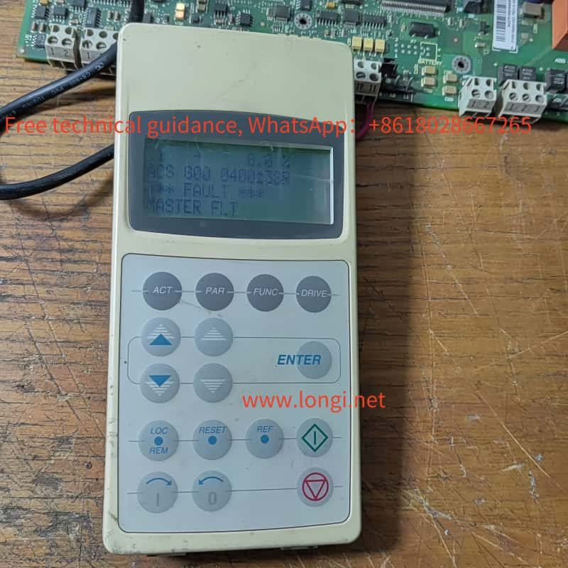
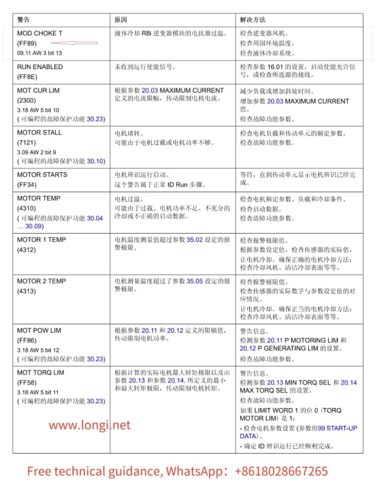
Alarm Message: FF89 – MOD CHOKE T (FF89) 09.11 AW 3 bit 13
Cause:
Overheating of Reactor in Liquid-Cooled R8i Inverter Module The reactor in the liquid-cooled R8i inverter module has exceeded its temperature threshold.
Resolution Steps:
Check the Inverter Fan:
Ensure the inverter fan is operating properly and providing sufficient cooling to the reactor.
Inspect for any blockages or dirt accumulation that may impede airflow.
Inspect Ambient Temperature:
Verify that the ambient temperature surrounding the VFD is within the recommended range.
Ensure there are no heat sources in close proximity that could contribute to overheating.
Examine the Liquid Cooling System:
Thoroughly check the condition of the liquid cooling system, including pipes, pumps, and radiators.
Confirm that the coolant flow rate and temperature are within normal operating parameters.
Inspect for leaks or corrosion that could indicate a need for maintenance or replacement.
Review VFD Operation and Configuration:
Ensure the VFD is not operating under excessive load conditions that could lead to overheating.
Check the VFD’s settings and parameters to verify they are appropriate for the application and load requirements.
Check for Alarms or Warnings in the VFD’s Diagnostic System:
Use the VFD’s diagnostic tools or software (such as DriveWindow) to check for any additional alarms or warnings that may provide further insight into the issue.
Service and Maintenance:
If the above steps do not resolve the issue, consider scheduling preventive maintenance or contacting ABB support for further assistance.
By following these resolution steps, you can effectively diagnose and address the FF89 alarm on your ABB ACS800 VFD, ensuring reliable and efficient operation of your industrial automation system.
Modifying the power ratings on ABB ACS800 series VFD (Variable Frequency Drive) control boards can be performed following a set of detailed steps, depending on the firmware version of the RDCU (Remote Digital Control Unit) board. This guide outlines the processes for both pre-version 7200 and post-version 7200 RDCU boards.
Pre-Version 7200 RDCU Power Rating Modification Steps
Enter 9903 and set to YES:
Access the control panel and navigate to parameter 9903.
Set the value to YES to enable modification mode.
Enter 1603 and set to 564:
Navigate to parameter 1603 and enter the passcode 564.
This unlocks access to parameter groups 112 and 190.
Select XXNONE in 11206:
Navigate to parameter 11206 and select XXNONE.
This prepares the board for power cycle.
Power Cycle:
Turn off the power to the RDCU board.
Wait a few seconds and then turn the power back on.
Re-enter 1603 and set to 564 (again):
Repeat step 2 to ensure the passcode is active.
Select the Desired Power Rating in 11206:
Navigate to parameter 11206 again and select the desired power rating (e.g., 170-3).
Initialize Parameters:
Perform any necessary parameter initialization steps as recommended by the manufacturer’s guidelines.
Final Power Cycle:
Repeat the power cycle process to ensure the new settings take effect.
Post-Version 7200 RDCU Power Rating Modification Steps
Enter 9903 and set to YES:
Same as the pre-version 7200 steps.
Enter 1603 and set to 564:
Same as the pre-version 7200 steps.
Select the Desired Power Rating Directly in 11221:
Instead of using 11206, navigate to parameter 11221 and directly select the desired power rating (e.g., 11221 = sr170_3).
Re-enter 9903 and set to YES (optional):
Depending on the specific firmware, this step may be optional but recommended for confirmation.
Power Cycle:
Turn off the power to the RDCU board and then turn it back on.
Notes and Cautions
Parameter Ranges: Note that parameters 11219 to 11223 represent different power ratings. Ensure you select the correct one for your application.
Normal Usage Caution: Do not modify the settings on a normally operating VFD unless absolutely necessary, as it may result in the loss of important operational parameters.
Firmware Differences: Always refer to the latest ABB documentation for your specific firmware version, as steps may vary slightly between versions.
Parameter Unlocking: Remember that entering 564 in parameter 1603 unlocks advanced parameters, allowing for the modification of power ratings and other settings.
By following these steps carefully, you can safely modify the power ratings of ABB ACS800 series VFD control boards, ensuring optimal performance and compatibility
A centrifuge is a device that utilizes centrifugal force to separate different components in a mixture. Its working principle is based on Newton’s second law, where the centrifugal force experienced by an object during rotation is proportional to the square of the angular velocity and the radius of rotation, and also proportional to the mass of the object. In a centrifuge, substances are placed on a rotating turntable and accelerated along with it. As the rotation speed increases, the substances experience centrifugal force, leading to their separation into different components. Factors such as the rotation speed, turntable diameter, and turntable material of the centrifuge all influence the magnitude of the centrifugal force and the effectiveness of the separation.
I. Operation Method of the Centrifuge
The operation of a centrifuge generally involves the following steps:
Preparation Stage:
Check if the centrifuge is in normal working condition.
Prepare necessary centrifuge tubes, turntables, and other accessories.
Loading Samples:
Place the substances to be separated into centrifuge tubes.
Position the centrifuge tubes on the turntable of the centrifuge, ensuring they are correctly placed and evenly distributed to maintain balance.
Setting Parameters:
Set the parameters of the centrifuge, such as rotation speed and centrifugation time, according to the separation requirements and sample characteristics.
Starting the Centrifuge:
Press the start button to initiate the centrifuge.
Monitoring the Centrifuge:
Monitor the running status of the centrifuge during operation to ensure the centrifugation process proceeds normally.
Stopping the Centrifuge:
After centrifugation is complete, press the stop button, halt the centrifuge, and retrieve the separated substances.
II. Common Faults and Troubleshooting Methods for the Centrifuge
The centrifuge may encounter various faults during use. Below are some common faults and their troubleshooting methods:
Unbalanced Centrifuge or Uneven Placement of Centrifuge Tubes:
Adjust the level of the centrifuge to ensure it is stable.
Evenly distribute the centrifuge tubes to avoid imbalance caused by uneven weight distribution.
Loose or Damaged Rotor:
Check if the rotor is loose or damaged, and replace it if necessary.
Loose Screws, Worn Bearings, or Motor Faults:
Tighten the screws of the centrifuge.
Check for bearing wear and replace if necessary.
Check for motor faults and repair or replace if needed.
Blocked Oil Filter or Oil Leakage:
Inspect the oil filter, oil pipes, and connectors to ensure they are unblocked.
Check for oil leakage and repair promptly if found.
Power Issues or Damaged Circuit Board:
Check if the power plug is properly inserted and the power cord is energized.
Check if the fuse is burned out and try replacing it.
If the above are normal, the circuit board may be damaged and needs to be returned for repair or replacement.
Water Circuit Issues or Damaged Seal Rings:
Check if the water circuit is unblocked and the solenoid valve is functioning properly.
Inspect the seal rings for damage or impurities and replace if necessary.
III. Maintenance Methods for the Centrifuge
The maintenance of a centrifuge mainly includes the following steps:
Cleaning:
Regularly clean the centrifuge to remove accumulated dirt and residues, restoring the design dimensions of the cavity.
Inspection:
Regularly inspect various components of the centrifuge, including feed pipes, drums, spirals, housing, frames, and motors, to ensure they are in normal structure and working condition.
Calibration:
Regularly calibrate the assembly components of the centrifuge to ensure good dynamic balance.
Lubrication:
Regularly lubricate the bearings, gears, and other components of the centrifuge to reduce wear and extend service life.
Maintenance:
Regularly maintain the centrifuge, including replacing worn components and cleaning internal dirt.
Fault Diagnosis:
Promptly diagnose the cause of any faults in the centrifuge through methods such as listening to sounds, checking the power supply, and viewing fault codes on the display. Seek professional assistance if unable to resolve.
IV. Centrifuge Brands and Models Repaired by Longi Electromechanical Company
Beckman Coulter:
Avanti JXN-30
Avanti JXN-26
Allegra X-30 Series
Allegra V-15R
Microfuge 20 Series
Optima XE/XPN Series (XE/XPN-90, XE/XPN-100, XE/XPN-80)
Longii Electromechanical Company has nearly 30 years of experience in repairing centrifuges and can quickly repair various instruments. Additionally, we recycle and sell various used centrifuges. Welcome to consult with us.
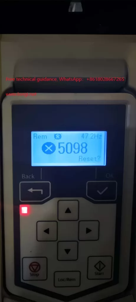
ACS530 VFD 5098 Alarm Fault Analysis and Troubleshooting
When working with ABB’s ACS530 series VFDs (Variable Frequency Drives), encountering specific fault alarms such as the 5098 alarm can be a concern. While the ACS530 series manual may not directly mention this alarm code, by referencing the manual of its similar ACS580 series VFDs, also from ABB, we can gain insight into the 5098 alarm and apply that knowledge to troubleshooting the ACS530 series.
I. Understanding the 5098 Alarm
In the ACS580 series, the 5098 alarm indicates “I/O Communication Lost,” signifying a failure in communication with the standard I/O (Input/Output) devices. This usually occurs when there is an issue with the communication link between the VFD’s I/O terminal board (where analog inputs like AI1 reside) and the main board. Similarly, in the ACS530 series, the 5098 alarm likely indicates a communication issue as well.
II. Possible Causes of the Fault
Power Issues:
The 10V or 24V power supply on the I/O terminal board may be abnormal, leading to unstable or failed communication.
There may be short circuits, open circuits, or poor connections in the power lines.
Hardware Connection Problems:
Connections between the I/O terminal board and the main board may be loose, have cold solder joints, or be corroded.
Terminals may have aged due to prolonged use, resulting in poor contact.
Communication Module Failure:
The VFD’s I/O communication module may be damaged, preventing proper communication with the I/O terminal board.
Software or Configuration Issues:
The VFD’s software configuration may have errors, affecting communication protocols or parameter settings.
Despite similarities in design and software between the ACS530 and ACS580 series, subtle differences in configuration may lead to unexpected alarms in the ACS530 under certain conditions.
III. Fault Troubleshooting Steps
To address the 5098 alarm in the ACS530 VFD, follow these troubleshooting steps:
Check Power Supplies:
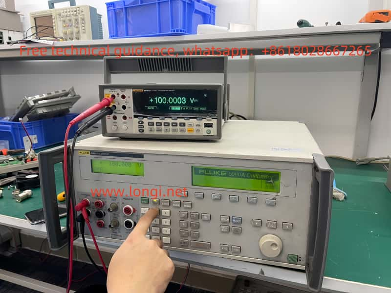
Use a multimeter to verify the 10V and 24V power supplies on the I/O terminal board are functioning correctly.
Inspect power lines for completeness, shorts, or open circuits.
Inspect Hardware Connections:
Disconnect all connections related to the I/O terminal board, reconnect them securely, and ensure they are tight.
Examine the connections between the I/O terminal board and the main board for looseness, cold solder joints, or corrosion, and make necessary repairs.
Assess Communication Module:
If possible, test replacing the I/O communication module with an identical one to determine if it’s faulty.
Reset and Restart:
Attempt to reset the VFD to clear the alarm.
If resetting fails, power off the VFD, wait for a while, and then power it back on to eliminate any software-related communication issues.
Contact Technical Support:
If none of the above steps resolve the issue, contact ABB’s technical support team or a professional service provider for further diagnosis and repair.
IV. Conclusion
Despite the ACS530 series VFD manual’s lack of direct mention of the 5098 alarm, referencing similar ACS580 series documentation and contextual analysis enables understanding the likely fault type and appropriate troubleshooting methods. In practice, consider all potential causes
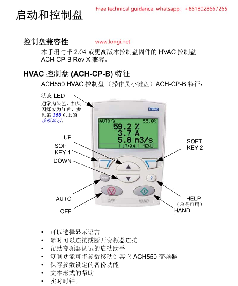
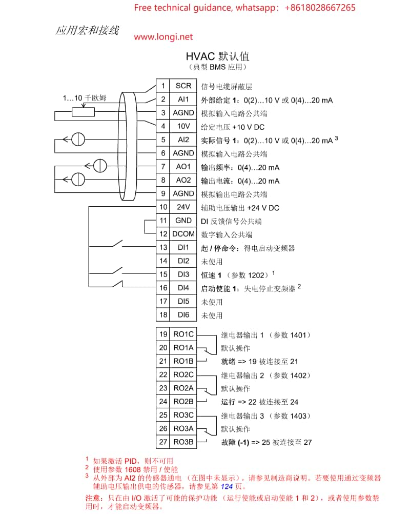
The operating panel (control pad) of the ACH550 inverter serves as the primary interface between the user and the inverter, enabling status display, parameter setting, and operation control.
2. Basic Operations
Starting and Stopping:
Press “HAND” Button: Enters manual mode, allowing adjustment of inverter output frequency via the up and down arrow keys.
Press “AUTO” Button: Switches to automatic mode, where inverter operation is controlled by external signals (such as terminal signals or communication signals).
Display Mode Switching:
Access different display modes (e.g., output mode, parameter mode, assistant mode) through the menu button (MENU) on the control pad.
Parameter Setting:
In parameter mode, use the up and down arrow keys to select the parameter to modify. Press the edit button (EDIT) to enter the parameter settings, input new values using the numeric keys, and save changes with the save button (SAVE).
3. Assistant Mode
The assistant mode provides guided steps for starting and configuring the inverter, ideal for first-time users or those requiring quick setup.
II. Terminal Starting and Potentiometer Speed Control
1. Terminal Starting Wiring
Connect Main Power: Wire the inverter’s input power to the corresponding terminals (U1, V1, W1).
Connect Motor: Connect motor wires to the inverter’s output terminals (U2, V2, W2).
Control Signal Wiring:
Connect the start signal (e.g., DI1) to the inverter’s digital input terminal.
If direction control is required, connect the direction signal to the corresponding terminal (e.g., DI2).
2. Potentiometer Speed Control Wiring
Potentiometer Selection: Choose an appropriate rotary or slide potentiometer.
Wiring:
Connect the three pins of the potentiometer to the inverter’s analog input terminals (e.g., positive, negative, and signal terminals of AI1).
Adjust the potentiometer knob to vary the voltage or current signal input to AI1, thereby controlling the inverter’s output frequency.
3. Parameter Setting
Enter parameter mode and select an appropriate macro (e.g., fan macro or general PID macro) that presets parameters suitable for specific applications.
Adjust parameters related to start/stop, direction control, and analog inputs based on actual wiring configurations.
III. Inverter Fault Code Analysis and Troubleshooting
1. Fault Code Inquiry
Display recent fault codes through the control pad, which correspond to different fault types.
2. Common Fault Codes and Troubleshooting Methods
Overcurrent Fault:
Cause: Motor overload, motor short circuit, improper parameter settings, etc.
Solution: Check motor and load conditions, adjust overload protection parameters, and confirm inverter and motor parameter compatibility.
Undervoltage Fault:
Cause: Low or fluctuating input power voltage.
Solution: Verify power supply voltage stability, increase input filter capacitors, or adjust undervoltage protection thresholds.
Overheat Fault:
Cause: Poor inverter cooling, high ambient temperature.
Solution: Improve inverter cooling conditions, such as installing additional cooling fans or reducing ambient temperature.
Communication Fault:
Cause: Communication line issues, incorrect communication parameter settings.
Solution: Check communication line connections, ensure communication parameter settings match the device configuration.
IV. Precautions
Always disconnect inverter power before performing any wiring or parameter adjustments.
Observe control pad status indicators and fault codes during operation, promptly addressing potential issues.
For complex faults or unsolvable problems, contact ABB technical support or a qualified service
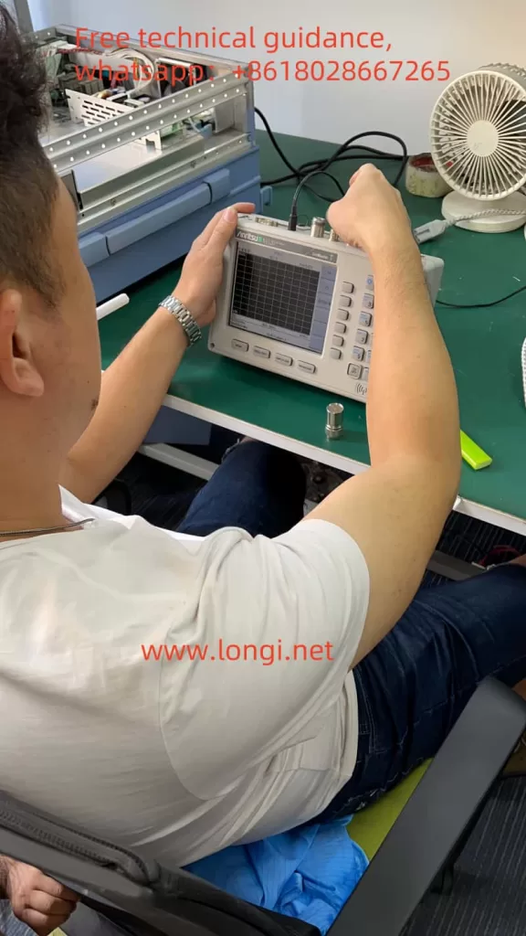
Indicators: Front panel power indicator not lit, fan not rotating, network analyzer unable to start normally, or constant resetting due to unstable power supply voltage.
Display Faults:
Manifestations: No display (black screen), scrambled screen, grayscale display. Possible causes include monitor failure, graphics processing board failure, or CPU failure.
Local Oscillator Faults:
Issues: Local oscillator unlock, low local oscillator power resulting in high signal insertion loss, and poor local oscillator spectrum purity.
Signal Path Faults:
Components affected: Input connectors, signal cables, attenuators, preselectors, frequency converters, intermediate frequency amplification/filtering, data acquisition and processing.
Processor Faults:
Primarily involve processor hardware and program (software) faults, with the latter being more common.
II. Solutions
Power Supply Fault Repair:
Check power cord connections and power outlets to ensure proper power supply.
Replace the power module or repair the power circuit if the power indicator is not lit or the fan does not rotate.
Display Fault Repair:
Inspect display cable connections and related circuit boards for proper connection.
Replace the display or relevant circuit boards if the issue persists.
Local Oscillator Fault Repair:
Examine local oscillator circuit boards and connections for damage or looseness.
Adjust the local oscillator circuit or replace relevant components if there is unlock or low power.
Signal Path Fault Repair:
Check all components in the signal path, including input connectors, signal cables, attenuators, etc., for secure connections and proper functioning.
Replace or repair faulty components promptly.
Processor Fault Repair:
Restart the instrument and check software settings for any program errors or configuration issues.
Reset the processor or reinstall software if the problem remains.
Preventive Measures:
Ensure proper grounding to avoid electrostatic interference.
Read and follow instrument technical specifications and warning labels.
Pay attention to electrostatic protection, especially for exposed interfaces.
Maintain good instrument ventilation and avoid blocking air outlets.
When performing DC input, ground the equipment before connecting the power supply.
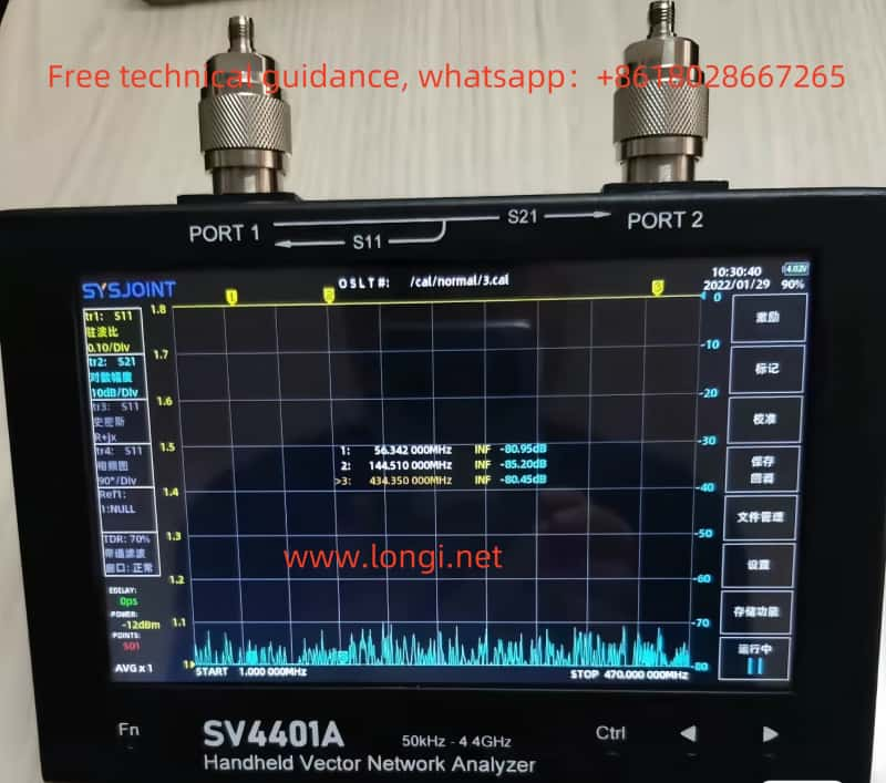
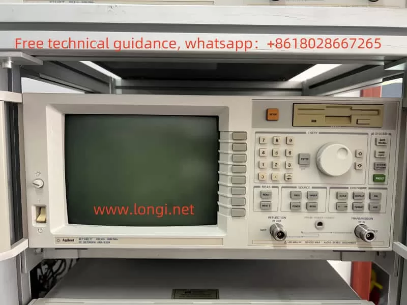
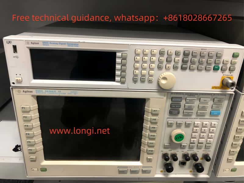
AV36580A: A new-generation vector network analyzer with multiple communication functions, automated testing capabilities, and wide test applications.
Other Brands:
SAMZHE, Fluke, Spirant, Ideal Industries (USA)
Repair and Sales Services
Longi Electromechanical Company specializes in the repair of network analyzers (including wireless spectrum analyzers, antenna feeder VSWR testers, Ethernet testers, network synthesis testers, vector network analyzers, real-time spectrum analyzers, USB vector network analyzers) with nearly 30 years of experience. We provide quick repairs for various instruments and also offer sales and recycling of used network analyzers. Feel free to contact us for more information.
Fault Causes: Insufficient light emission from the source, damaged or dusty detector, misaligned or shifted optical path.
Optical Path Obstruction:
Clear the sample or optical path.
Check for damaged components or dust in the optical path and clean or replace as necessary.
Fault Causes: Sample residue in the optical path, blockages such as damaged components or dust.
Vacuum Pump Not Starting:
Ensure consistency between pump and oil models, and regularly replace pump oil.
Adjust indoor temperature to avoid excessively low temperatures.
Check and manually start the pump motor via the analysis software.
Fault Causes: Poor viscosity or incorrect model of pump oil, temperature-related issues, control signal problems.
Sudden Loss of Negative High Voltage:
Try unplugging and replugging the second ground wire of the control box; if unsuccessful, consider restarting the instrument.
Fault Cause: Vacuum value not rising for an extended period.
Low Light Intensity:
Clean the condensing lens.
Clean the slit.
Replace the corresponding photomultiplier tube.
Fault Causes: Dirty condensing lens, dirty slit, degraded performance of the photomultiplier tube.
Unstable Instrument Analysis Data:
Check and replace the rear fan of the instrument if necessary.
Fault Causes: Poor temperature control in the instrument’s vacuum chamber, faulty rear fan operation.
Poor Communication Line Contact Leading to Computer Crash or Program Error:
Reconnect the communication line.
Exhaust Blockage:
Replace the exhaust pipe with a transparent plastic tube and regularly purge the exhaust line.
Fault Causes: Blocked argon exhaust line, debris in the lower bend of the spark chamber, debris at the inlet of the argon filter.
Power, Connection, or Software Issues:
Check for proper power connection, damaged or loose power cords.
Ensure correct and undamaged connection of cables.
If software issues occur, attempt reinstallation or updating.
Other Maintenance and Calibration:
Regularly clean the optical components of the spectrometer and perform calibration to ensure accuracy.
Note: The above solutions are for reference only. For specific faults, it is recommended to contact Rongji Electromechanical for professional repair and support.
II. Supported Spectrometer Brands by Rongji Electromechanical
Niton Spectrometers (Thermo Fisher Scientific):
Niton XL2, Niton XL2 Plus, Niton XL5 Plus, Niton DXL Precious Metal Analyzer, Niton XL2 100G General Metal Analyzer, Niton Apollo Handheld LIBS Analyzer.
EDX Series, SUPERXRF1050, Explorer8000 Series, SEE 100, SEE 200, ZSX Primus Series, XEPOS.
Nanjing Sanxiang Spectrometers:
THICK800A, EDX4500H.
Longi Electromechanical offers long-term maintenance for various types of spectrometers, including infrared, Raman, fluorescence, direct-reading, UV-Vis, and more. With nearly 30 years of experience, we can quickly repair various instruments. Additionally, we recycle and sell used spectrometers. For more information, please contact us.
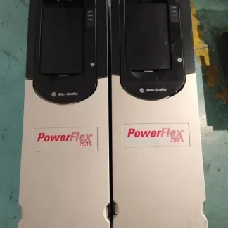
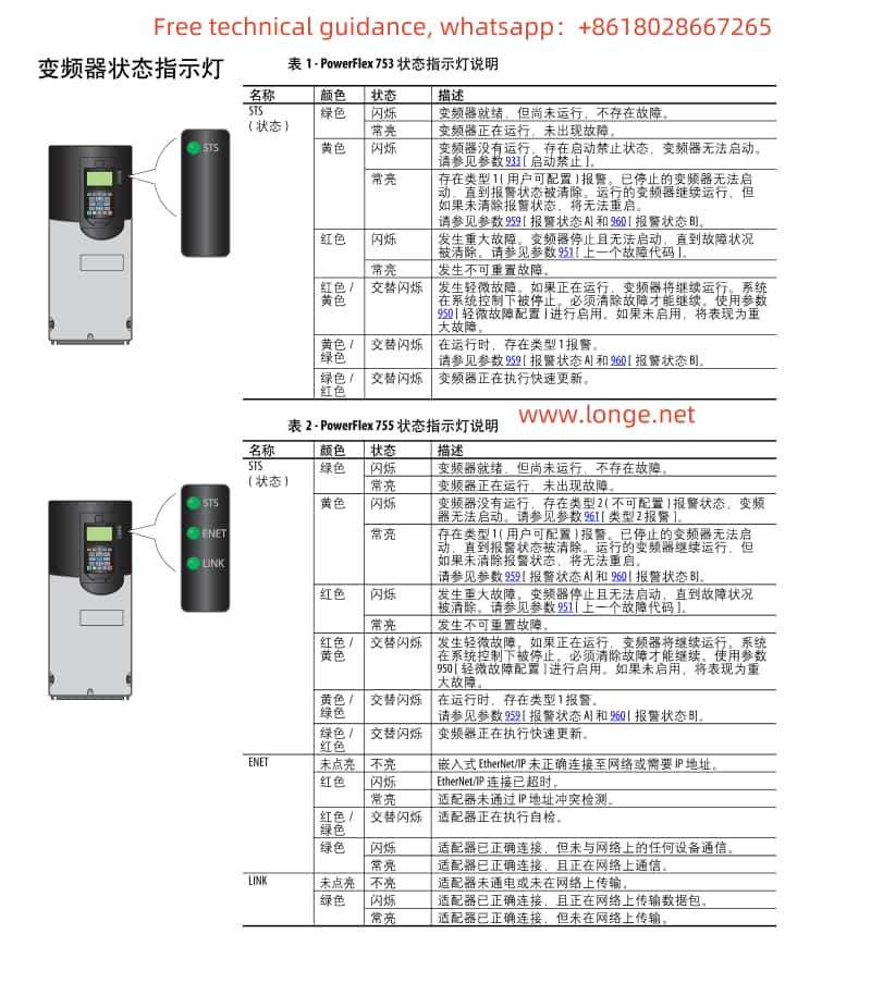
The operation panel (keypad) of the PowerFlex 750 series AC drive serves as the primary interface for user interaction. It allows users to navigate menus, set parameters, and view status information.
Navigation and Selection: Use the arrow keys to navigate through menus and the “Select” button to enter specific settings or parameter editing mode.
Parameter Editing: In edit mode, enter or adjust parameter values using the numeric keys or arrow keys.
Saving and Exiting: After making changes, use the “Save” button to save modifications and the “Exit” button to return to the previous menu or the main interface.
Status Viewing: Select the appropriate option from the menu to view the drive’s output frequency, current, voltage, fault codes, and other status information.
2. Open-Loop V/F Control Parameter Settings
In open-loop V/F (Volts per Hertz) control mode, the drive regulates the motor speed by adjusting the ratio between the output voltage and frequency. Here are guidelines for setting key parameters:
P35 (Motor Control Mode): Set to “V/Hz” mode to enable open-loop V/F control.
P25 (Motor Nameplate Voltage): Enter the motor’s rated voltage.
P27 (Motor Nameplate Frequency): Input the motor’s rated frequency.
P60 (V/F Curve Settings): Adjust the V/F curve as needed to optimize motor performance.
P520/P521 (Maximum Forward/Reverse Speed): Set the maximum operating frequency limits for the motor.
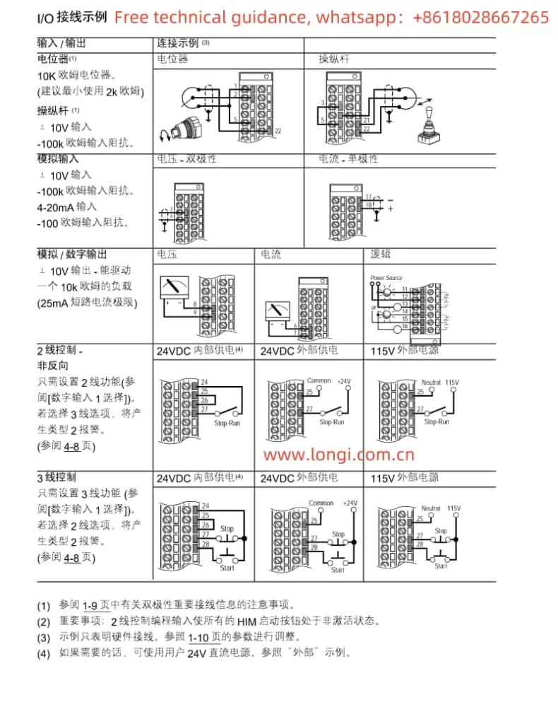
3. Terminal Start and Potentiometer Speed Adjustment Wiring and Parameter Settings
Wiring Instructions:
Main Power and Control Power Connection: Connect the three-phase main power and (if required) control power as specified in the manual.
Motor Connection: Wire the motor’s three-phase leads to the U, V, W output terminals.
Start/Stop Terminal Connection: Connect the contacts of the external start/stop buttons to the drive’s DI (Digital Input) terminals and configure the related parameters.
Potentiometer Speed Adjustment Connection: Connect the potentiometer’s wiper to the AI (Analog Input) terminal for speed regulation.
Parameter Settings:
Digital Input Configuration: Configure relevant parameters to assign DI terminals for start/stop functions.
Analog Input Configuration: Ensure AI terminals are set as the speed reference source and adjust the input range to match the potentiometer’s output range.
Speed Reference Selection: Specify the analog input as the source for speed references in the parameters.
4. Fault Code Analysis and Troubleshooting Summary
According to the fault code list provided in the manual (pages 316-323, fault numbers 0-155), here are summaries of a few common faults, their possible causes, and troubleshooting methods:
F001: Overcurrent Protection. Check for motor overload, stable power supply voltage, and short circuits in the output circuit.
F002: Overvoltage Protection. Verify that the input voltage is within the allowed range and consider installing a voltage stabilizer or adjusting the input filter.
F003: Undervoltage Protection. Check if the power supply voltage is too low and confirm correct power line connections.
F004: Overheat Protection. Inspect the drive and motor cooling, clean dust from the heat sink, and ensure proper ventilation.
F005: Communication Failure. Check communication line connections, verify correct communication parameter settings (including baud rate, data bits, etc.).
Please note, the above fault codes are examples, and specific fault codes and their solutions should be referenced directly from the manual.
5. General Troubleshooting Steps
Check Fault Code: Read and record the fault code on the operation panel.
Consult the Manual: Look up the corresponding fault description, possible causes, and solutions in the manual.
Perform Preliminary Checks: Examine power sources, motors, communication lines, etc.
Reset the Drive: If initial checks reveal no issues, attempt to reset the drive to clear temporary faults.
Advanced Diagnostics: If problems persist, professional tools may be
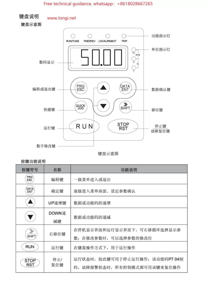
The operation panel (keyboard) of the CHF100A Series Vector Universal VFD serves as the primary interface for VFD control and parameter setting. Here are the basic keyboard operation methods:
Power-on and Display:
Upon connecting the VFD’s power supply, the display on the operation panel will illuminate, showing the current status or default parameters.
Key Functions:
PRG: Programming key, used to enter or exit parameter setting mode.
SHIFT: Shift key, combined with numeric keys to select or modify high-order digits of parameters.
ESC: Escape key, used to exit the current setting or menu.
ENT: Enter key, used to confirm current settings or selections.
DATA: Data toggle key, used in some settings to switch between displaying different data items.
Parameter Setting Procedure:
Press the PRG key to enter parameter setting mode.
Use arrow keys (if equipped) or SHIFT + numeric keys to select the desired parameter number.
Press the ENT key to enter the parameter’s setting interface.
Modify the parameter value using arrow keys or numeric keys.
Press the ENT key again to confirm the setting.
Press the ESC key to exit parameter setting mode.
II. VFD Terminal Startup and Potentiometer Speed Regulation Wiring
Terminal Startup Wiring:
Refer to the electrical wiring diagram in the manual (typically around page 75) to locate the input terminals related to startup (e.g., S1, S2).
Connect the external startup signal (e.g., pushbutton switch, PLC output) to the corresponding startup terminals.
Configure parameters as needed to ensure the VFD recognizes and responds to these startup signals.
Potentiometer Speed Regulation Wiring:
Locate the analog input terminals (e.g., AI1, AI2) on the VFD, which receive analog signals from the potentiometer.
Connect the wiper of the potentiometer to the AI1 or AI2 terminal, and the fixed terminal to the common ground (e.g., COM).
Adjust the potentiometer to vary the output signal, thereby controlling the VFD’s output frequency and motor speed.
III. VFD Fault Code Analysis and Troubleshooting
When a CHF100A Series VFD encounters a fault, it displays the corresponding fault code on its screen. Here are some common fault codes, their analysis, and troubleshooting methods:
OC (Overcurrent):
Cause: Excessive motor or load, output short circuit, faulty cabling or wiring.
Solution: Check the motor and load to ensure they are within normal ranges; inspect cabling and wiring for correctness; increase deceleration time or reduce acceleration current.
Solution: Improve ventilation to enhance cooling, reduce ambient temperature; clean dust and debris from the heat sink.
Please note that these are exemplary analyses and solutions. Always refer to actual circumstances and detailed instructions in the manual. When dealing with any electrical fault, adhere strictly to safety procedures and consider power disconnection to avoid electrical shock risks.
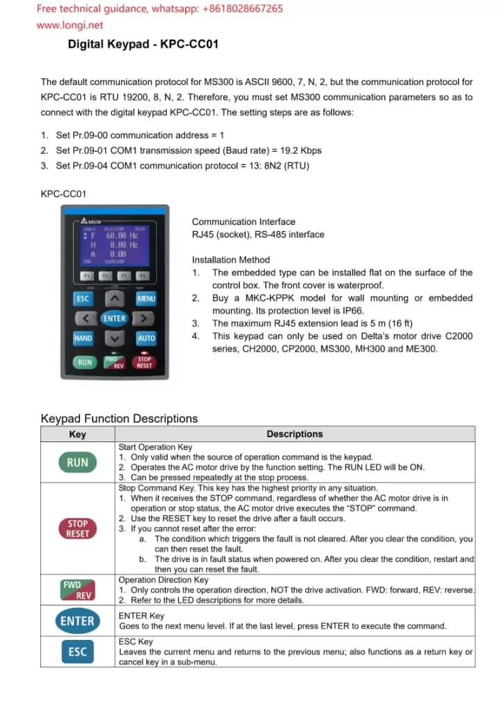
Upon powering on, the VFD automatically conducts a self-test and then enters standby mode. The display on the operating panel shows the current status and parameters.
Function Key Operations
RUN/STOP Button: Press RUN to start the VFD and STOP to halt its operation.
Direction Selection (FWD/REV): Used to select forward or reverse rotation for the motor.
Frequency Adjustment Keys: Adjust the output frequency using the up and down arrow keys. In automatic mode, these keys may be disabled.
MENU Button: Enters the main menu, allowing access and modification of various settings.
ENTER Button: Confirms the current selection or enters setup mode.
ESC Button: Exits the current setup or returns to the previous menu level.
Parameter Settings
Navigate to the parameter settings menu, use the arrow keys to select the parameter to modify, press ENTER to enter edit mode, adjust the parameter value with the up/down arrow keys, and confirm with ENTER.
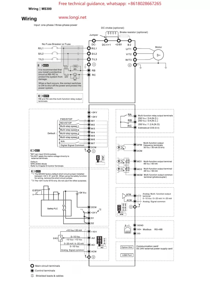
II. Wiring for Terminal Start and Potentiometer Speed Control
Starting Terminal Wiring
Forward Start (FWD): Connect the external control signal to the VFD’s forward start terminal (e.g., FWD).
Reverse Start (REV): For reverse rotation, connect the signal to the reverse start terminal (e.g., REV). Typically, forward and reverse cannot be activated simultaneously.
Stop: Connect the stop signal to the VFD’s stop terminal to interrupt output.
Potentiometer Speed Control Wiring
Connect a potentiometer to the analog input terminal (e.g., AVI or ACI) of the VFD. Attach the two fixed ends of the potentiometer to the VFD’s power supply (e.g., +10V and GND), and connect the sliding end to the VFD’s analog input terminal.
According to the parameter settings in the manual (e.g., parameter 03-00), configure the relevant parameter to “frequency command” so that the VFD can adjust its output frequency based on the voltage signal from the potentiometer.
III. Parameter Configuration
Basic Parameter Settings
Maximum Operating Frequency (Parameter 01-00): Set the maximum output frequency based on the motor specifications.
Acceleration/Deceleration Time (Parameters 01-12 through 01-19): Configure appropriate acceleration and deceleration times to avoid mechanical shocks and overcurrents, tailored to your application’s needs.
Starting Frequency (Parameter 01-09): Set the initial frequency at startup to mitigate starting surges.
Input/Output Terminal Configuration
Multi-function Input Terminals (Parameters 02-01 through 02-07): Assign each terminal’s function according to your control requirements, such as start, stop, and direction control.
Analog Input Configuration (e.g., Parameter 03-00): Specify the function of AVI, ACI, and other analog input terminals, such as frequency reference or torque control.
Protection Parameters
Overcurrent Protection (Parameters 06-03 through 06-04): Configure the overcurrent protection threshold and duration to safeguard the motor and VFD.
Overvoltage/Undervoltage Protection (Parameters 06-00, 06-01): Set voltage protection thresholds to ensure stable operation amidst voltage fluctuations.
IV. Fault Code Analysis and Resolution
Overcurrent (OC)
Cause: Excessive motor load, too short acceleration time, motor malfunction, etc.
Resolution: Inspect the motor and load conditions, adjust the acceleration time, and check for motor damage.
Overvoltage (OV)
Cause: Excessive input voltage, too short deceleration time, insufficient braking resistance, etc.
Resolution: Verify the input voltage, adjust the deceleration time, and consider adding braking resistance.
Undervoltage (LV)
Cause: Low input voltage, voltage drop due to long power lines, etc.
Resolution: Check the power supply voltage and optimize power line layout.
Overheating (OH)
Cause: High ambient temperature, poor heat dissipation, excessive load, etc.
Resolution: Improve cooling conditions, reduce the load, and inspect and clean the cooling fan.
Communication Fault
Cause: Communication line issues, incorrect parameter settings, address conflicts, etc.
Resolution: Examine the communication lines, verify communication parameter settings, and ensure unique device addresses.
By following this guide, you can effectively use and maintain the Delta VFD MS300 series, ensuring stable operation and optimal performance.