Posted on

S7-1500 Memory Card Offline Programming Process and Analysis of “Empty Card” Issues

I. Correct Process for Offline Programming of S7-1500 Memory Cards in TIA Portal

In TIA Portal, you can directly download a compiled project offline to an SIMATIC memory card for the S7-1500, creating a “program transfer card” for loading programs onto the PLC without an internet connection. The recommended steps are as follows:

Hardware Preparation: Use an official Siemens SD card reader and insert an SIMATIC memory card (e.g., 6ES7 954-8LC04-0AA0) into the computer’s USB port. Ensure the card is not write-protected (slide the side switch to the unlocked position). TIA Portal will automatically recognize the card reader.

Memory Card Identification: In the TIA Portal project tree, expand the “Card Reader/USB Memory” node to view the corresponding memory card drive (e.g., “(G:) SIMATIC MC [Program]”). If it does not appear, refresh it via the menu “Online > Display SIMATIC Card Reader”.

Download Project to Memory Card: Select the CPU station in the project tree (e.g., “PLC_1 [CPU 1516-3 PN/DP]”) and drag it to the memory card drive node. Release the mouse, and TIA Portal will prompt a download dialog. Compile and confirm the write operation as instructed. Alternatively, use the menu option “Online > Write to Memory Card”.

Completion of Writing: If the project compiles and writes successfully, TIA Portal will indicate completion. The memory card now contains the program data files for PLC startup. Safely eject the card from the reader, insert it into the target S7-1500 CPU slot, and power on or reset the CPU to load the program from the card.

Additional Note: The drag-and-drop method generates an S7_JOB.S7S (or .SYS) file and a “SIMATIC.S7S” project folder on the memory card, containing all user program data for the PLC. This allows for offline upgrades without an online PLC connection. If TIA Portal is unavailable, generate the project to a PC folder or USB drive first, then transfer it to the memory card.

6ES7 517-3FP01-0AB0

II. Possible Reasons for Controller Identifying Memory Card as Blank

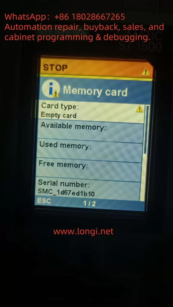
When an S7-1500 CPU displays “Empty card,” it means no valid user program has been detected on the card. For example, the memory card type is identified as “Empty card,” with 0 used space, as shown below.

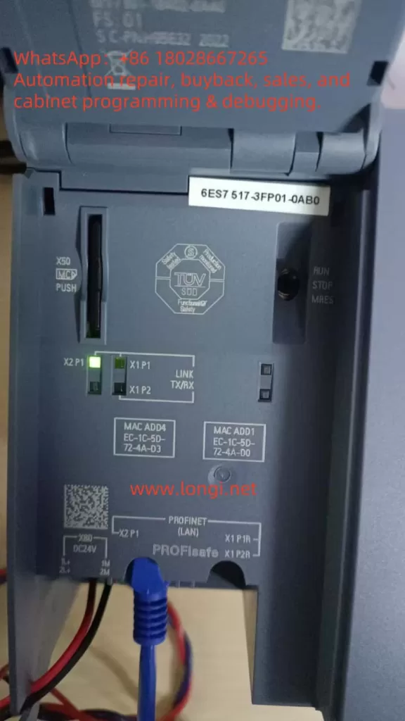
An S7-1517F CPU displays the memory card type as “Empty card,” indicating no valid program data has been detected.

Common causes include:

Unsuccessful Project Data Writing: If the offline programming process is not completed correctly (e.g., compilation without “Write to Memory Card” execution, or interruption during download), the card may lack the S7_JOB.S7S file and “SIMATIC.S7S” folder. The CPU will then treat the card as empty. Interruptions (e.g., network/power failures) can result in incomplete project data, preventing CPU recognition.

Memory Card File System or Structure Issues: SIMATIC memory cards for S7-1500 use the FAT32 format with pre-installed hidden system files. Non-official formatting, accidental deletion of hidden files, or file system errors can prevent CPU recognition. For instance, hidden “LOG” and “crdinfo.bin” files are essential for card identification; their deletion or corruption may render the card unrecognizable, causing the CPU to treat it as uninitialized and blank.

Project-CPU Incompatibility: Although not directly causing an “empty card” display, if the card contains a higher-version project unsupported by the CPU firmware or inconsistent project data, the CPU may ignore the card contents. For example, a project version higher than the current TIA Portal engineering version may prevent loading (though the CPU displays an empty card, it actually does not recognize the program). Resolving version mismatches requires firmware upgrades or project regeneration.

Hardware or Operational Factors: A damaged or poorly connected memory card can also cause reading failures. Ensure the card is not write-protected; otherwise, while the CPU can read the program, TIA Portal will reject writes (write protection does not cause a blank card but prevents program updates).

Note: According to Siemens official manuals, an “empty memory card” lacks the user program job file (S7_JOB.S7S) and project data folder (SIMATIC.S7S). When detecting an empty card, the S7-1500 CPU will attempt to copy its internal load memory contents to the card (and clear the internal memory) by default or remain unchanged if automatic copying is prohibited. If the CPU also lacks a program, inserting an empty card will leave it without a user program to run, necessitating normal downloads or offline programming as described.

III. Methods to Confirm Valid Program on Memory Card

To ensure the memory card contains a valid PLC program, verify the following:

Check Memory Card File Structure: Use Windows Explorer to open the memory card drive via the reader and check for the presence of the S7_JOB.S7S file and “SIMATIC.S7S” folder in the root directory. The S7_JOB.S7S file contains job instructions for CPU startup, while the “SIMATIC.S7S” folder holds compiled STEP 7 program block data (OBs, DBs, etc.). These files are essential indicators of successful TIA Portal programming; their absence indicates an unsuccessful write.

TIA Portal Property Check: Right-click the identified memory card drive in the TIA Portal project tree (e.g., “(F:) SIMATIC MC [Program]”) and select “Properties” to open the “Memory Card” dialog. Confirm the card type is “Program,” the file system is FAT32, and the used/available storage capacity matches the project size. For example, a 4MB card may show increased usage after programming. If the card remains blank or capacity is unchanged, the write operation likely failed, requiring a retry.

In TIA Portal, viewing SIMATIC memory card properties reveals the card type as “Program” and the file system as FAT32. If a project has been written, the card’s capacity usage should increase accordingly.

CPU Display and Status: Insert the card into the CPU and power it on. Observe the CPU display and indicator lights. Normally, the CPU should recognize the card as a “Program Card” and enter RUN mode. If it displays “Empty card” or remains in STOP mode, the program did not load successfully. Check the CPU panel’s “Memory Card Information” for project name/version (if available) to confirm CPU recognition.

Verify Operational Effect: Finally, observe the CPU’s RUN mode and controller behavior to indirectly confirm program loading. For example, if the program contains startup OBs or output logic, check the corresponding output states after power-on or use TIA Portal’s online monitoring (if connected) to verify CPU program blocks match the offline project.

Tip: SIMATIC memory card program data is encrypted and cannot be directly identified from file contents. However, file existence and structural integrity are sufficient to confirm successful programming. Always safely eject the memory card after writing to prevent incomplete writes or file corruption.

empty card

IV. Memory Card Recovery and Reprogramming Methods

If the memory card is still recognized as blank after insertion into the CPU, take the following steps to restore functionality:

Format via CPU Display: Switch the CPU to STOP mode and access the “Format Memory Card” function in the CPU’s LCD menu (usually under “Functions”). Confirm execution to clear all user data and rebuild the necessary system file structure. This method requires no additional software and is suitable for quick on-site card clearing. After formatting, the display should indicate card initialization.

Format via TIA Portal: Connect to the target CPU in TIA Portal (or via “Accessible Devices”) and open the “Online & Diagnostics” window. Navigate to “Functions > Format Memory Card,” click “Format,” and confirm. This restores the card to factory-blank status (retaining essential hidden files). After formatting, reprogram the card following the correct offline process.

Manual Cleanup via PC Reader: Insert the card into the reader and connect it to the computer. Open the card drive in Windows Explorer and delete the S7_JOB.S7S file and “SIMATIC.S7S” folder (and any other folders like DataLogs, Recipes, if present). Note: Do not format or delete invisible system hidden files (e.g., “LOG,” “crdinfo.bin”). After manual cleanup, the card becomes blank and can be reprogrammed via TIA Portal.

After any recovery step, reprogram the project data onto the memory card following the correct offline process. Ensure no old project residues remain on the card to prevent confusion with new data. If the card is suspected to be faulty (e.g., physical damage or end-of-life from repeated writes), replace it with a new SIMATIC memory card.

V. Siemens Official Guidelines on Programming Operations and Recognition Rules

Siemens provides detailed official documentation on SIMATIC memory card usage:

TIA Portal Offline Programming Process Guide: Siemens Industrial Support Center’s FAQ (Document ID 48711409) explains how to generate and store project data on S7-1200/1500 memory cards for offline program transfer to the CPU. It covers three methods: using a card reader, USB drive, or local folder, and describes the resulting file structure (including S7_JOB.S7S and SIMATIC.S7S).

Memory Card (Program Card) Usage Rules: The S7-1500 series user manual outlines memory card behavior as load memory (program card). For example, inserting a program card prompts the CPU to replace its internal program with the card’s program at startup and requires the card to remain in the CPU as external load memory. Removing the program card during operation stops the CPU and triggers an error due to the missing program. Regarding empty cards, the manual states that if an empty card is detected and automatic copying is not prohibited, the CPU copies its internal program to the card at power-on, then clears the internal memory. The CPU must then start from the card. These mechanisms govern how the S7-1500 determines if a memory card contains valid programs and takes appropriate actions.

Posted on

Troubleshooting Schneider ATV310 Drive Displaying –06 and Failing to Start or Run

1. Introduction: Symptoms and Background

In Schneider Electric’s Altivar ATV310 variable frequency drive (VFD), users may occasionally encounter the code --06 displayed on the integrated 7-segment LED screen. This condition is often accompanied by the motor being unable to start or respond to frequency commands. Although this may look like a fault, --06 is not an error code, but rather a status indication representing a special operating condition—usually “Freewheel Stop.”

This article explains the meaning of --06, identifies common causes, and walks you through practical steps to resolve the issue and restore normal operation.

--06

2. What Does --06 Mean?

The display code --06 on the ATV310 is an operational status code indicating that the drive is currently in Freewheel Stop mode, meaning output is disabled and the motor is freely coasting. This state is not caused by a fault but is often the result of control logic, input conditions, or communication states.

Other common drive statuses include:

  • --00: Drive ready (no run command)
  • --01: Fast stop
  • --06: Freewheel stop

While the drive is in --06, no output frequency is generated—even if run commands are issued—until the condition is cleared.


3. Common Causes of --06 Status

Several typical reasons could trigger the --06 state:

🟠 a. Logic Input Assigned to Freewheel Stop

If a digital input (e.g., LI1–LI4) is assigned to the Freewheel Stop function and is active, the drive will enter --06.

🟠 b. Incorrect Run Command in 2-Wire or 3-Wire Mode

  • In 2-wire mode (P201 = 2C), the drive needs a level-type run signal on LI1.
  • In 3-wire mode (P201 = 3C), a pulse-style start and stop logic is used.
    If wiring or configuration mismatches occur, the drive may fall into --06.

🟠 c. Serial Communication Without Proper Commands

If you’re controlling the drive via Modbus or RS-485, and the master does not send a valid start command (bit 0x6 = 1), the drive enters --06.

🟠 d. Analog Input Loss or Signal Drop

When using 4–20 mA input for speed control, a loss of input signal could trigger a fallback to freewheel stop.

🟠 e. Stop Button or Remote Stop Triggered

If the STOP key on the panel or an external STOP command is active, the drive may enter --06.

🟠 f. Residual State After Power Cycle

Sometimes the drive reboots directly into --06 if the prior control signals remain unchanged.


4. Step-by-Step Troubleshooting and Recovery

✅ Step 1: Check Control Mode and Logic Inputs

  • Confirm the control mode: P201 (2-wire/3-wire/serial).
  • Check P202, P203 for proper assignment of RUN/STOP logic inputs.
  • Use monitor mode (parameters 800–811) to observe input signal status.

✅ Step 2: Inspect Physical Inputs

  • Check if any logic inputs (e.g., LI1) are incorrectly triggered.
  • Look for short circuits, faulty switches, or wiring issues.

✅ Step 3: Check Analog/Serial Communication Settings

  • For analog control, verify AI1 input signal and scaling.
  • For Modbus, confirm that the master is sending the appropriate control word (bit 0x6 = 1).

✅ Step 4: Clear the Freewheel Stop and Restart

Option 1: Via Panel Navigation

  • Press ESC or MODE on the HMI.
  • Exit back to the main screen, wait for rdY (ready) to appear.

Option 2: Power Cycle

  • Power off the drive for 10 seconds, then power it back on.
  • The screen should return to --00 or rdY.

Option 3: Reassign Input Functions

  • Use P202 to change logic input function from Freewheel Stop to an unused input.
  • Set unused inputs to No Function (typically code 00).

ATV310

5. Ensuring Stable Operation After Recovery

After returning to normal status, take the following steps to avoid future issues:

  • ✅ Reassign logic inputs only when needed.
  • ✅ Avoid assigning STOP or Freewheel functions to frequently active lines.
  • ✅ Add debounce and safety logic in PLC/HMI control.
  • ✅ Enable fault auto-restart (parameter 602.0 = 01).
  • ✅ Use clear feedback loops if controlling via communication protocol.

6. Summary Table

StepDescription
Identification--06 is Freewheel Stop, not a fault
AnalysisCheck logic input functions, run mode, communication
ResolutionNavigate panel, correct wiring or reset power
OptimizationAdjust input definitions and enable self-recovery logic

7. Conclusion

The --06 display on a Schneider ATV310 is a common condition that can interrupt motor operation but is not an error. With proper diagnosis—by inspecting control signals, input assignments, or communication—this state can be quickly cleared.

Once resolved, implementing preventive logic configuration and enabling smart restart strategies can ensure robust and continuous drive performance in both standalone and automated systems.

If issues persist, contacting Schneider’s technical support or reviewing the full parameter manual is recommended.

Posted on

Toshiba VF-PS1 Inverter Stuck at “ELL0” with All LEDs Lit – Root Causes and Solutions

In the field of industrial automation, inverters play a crucial role in driving motors and optimizing energy efficiency. The Toshiba VF-PS1 series is known for its reliability and versatility across a wide range of applications such as manufacturing, HVAC systems, and water treatment. However, during a recent on-site startup, an unusual issue occurred: the inverter powered up and the screen continuously displayed “ELL0”, while all indicator LEDs on the operation panel (RUN, Hz, %, MODE, EASY, etc.) were fully lit and unresponsive. The device failed to transition to its normal frequency display or any operational mode.

ELL0

This article analyzes this abnormal behavior in depth, including its possible causes, technical diagnostics, and step-by-step troubleshooting solutions based on real-world experience. It aims to provide valuable insight for field engineers and maintenance professionals dealing with Toshiba VF-PS1 inverters.


1. Interpreting the “ELL0” Message

The first observation is that the code “ELL0” is not listed in the VF-PS1 manual’s error or alarm code tables. Most standard error codes for Toshiba inverters follow formats like E-xx (e.g., E-10 for analog input error, E-11 for sequence error) or Errx (e.g., Err4 for CPU fault).

Given this, “ELL0” is not a known error code but likely a simplified or stylized display of a word. Considering the limitations of seven-segment or basic LCD panels, the letter “H” may be rendered as “E”, resulting in the word “HELLO” being shown as “ELL0.”

In fact, several other Toshiba inverter series such as VF-S15 are documented to display “HELLO” during startup as a friendly greeting. While VF-PS1 manuals do not explicitly mention this, it is highly plausible that “ELL0” is simply the inverter saying “HELLO” at startup.

Conclusion: “ELL0” is not an error, but a startup message indicating the inverter is initializing.

However, this message is only meant to appear for a few seconds. If the inverter remains stuck on this screen for an extended time, and the display does not change to frequency output, “STOP,” or any other active status, then the system is failing to complete its initialization sequence.


2. Why Are All the LEDs Constantly Lit?

Electronic devices often illuminate all LEDs during the power-on self-test (POST) to confirm the panel is functional. The VF-PS1 has multiple LEDs on its keypad including RUN, Hz, %, MODE, and EASY.

In a normal power-up, these LEDs briefly flash and then only relevant indicators remain lit based on status:

  • In standby: only Hz and power indicators
  • In run mode: RUN LED is lit
  • During fault: alarm LED or fault code appears

⚠️ If all LEDs remain lit indefinitely, this suggests the system has not successfully exited the boot process. When combined with a stuck “ELL0” display, it is a clear sign the inverter is failing to transition to operational state.


VFAS1

3. Possible Technical Causes of the Fault

After analyzing the inverter’s architecture and behavior, the following are the most probable causes for this issue:

1. Main Control Board (CPU) Failure

The control board houses the CPU, EEPROM, and firmware that drive the entire system. If any of these components fail (e.g., due to static discharge, aging, memory corruption), the inverter may not proceed past startup, effectively freezing on the “HELLO” message.

2. Internal Control Power Supply Instability

Toshiba inverters typically generate low-voltage DC internally (e.g., 5V or 24V) to power logic and display. If these voltages are unstable due to aged capacitors or faulty switching circuits, the system may repeatedly attempt to initialize and fail each time.

3. Operator Panel Communication Failure

The panel communicates with the inverter’s main board through a connector or internal bus. If this link is disrupted—due to loose cables, damaged connectors, or panel PCB faults—the display might not receive valid data and remain stuck at its default state.

4. External Expansion Modules Interfering

If optional communication or I/O modules (e.g., Profibus, DeviceNet, or analog expansion) are connected and one of them malfunctions, it may prevent the system from passing its full self-test. This can effectively freeze the inverter before entering active status.

5. Corrupt Parameters or Firmware

Sudden power loss during write operations or faulty parameter resets may corrupt memory. If the inverter firmware or configuration table cannot initialize correctly, the inverter may hang during startup without even reporting an error.


4. Troubleshooting Steps and Solutions

The following field-tested steps may help restore the inverter to normal operation:

Step 1: Perform a Full Power Reset

  • Power off the inverter completely
  • Wait at least 15 minutes to allow internal capacitors to discharge
  • Re-energize and observe whether the display changes from “ELL0” to frequency display or run status

Step 2: Inspect the Panel Connection

  • If the keypad is external, check cable integrity and re-seat connections
  • If it’s an internal panel, check the physical contact to the main board
  • A faulty keypad may need replacement

Step 3: Remove Optional Modules

  • Disconnect any communication modules, expansion I/O boards, or external terminals
  • Reboot the inverter in minimal configuration
  • If the device initializes successfully, one of the peripherals is likely faulty

Step 4: Check Power Input and Control Voltage

  • Measure voltage at R/S/T terminals; confirm it’s within rated range and phase-balanced
  • If possible, measure internal low-voltage DC power (e.g., 5V or 24V) on the control board to ensure stability

Step 5: Attempt Parameter Initialization (if possible)

  • If the panel becomes responsive after reboot, consider resetting parameters to factory defaults
  • This may clear out any corrupt settings

Step 6: Consider Control Board Replacement

  • If none of the above steps restore operation, it’s likely the control board is faulty
  • Repair or replacement of the control PCB is required
  • Only qualified technicians should attempt internal board-level diagnostics

5. Preventive Measures

To avoid similar issues in the future:

  • Avoid frequent rapid power cycling, which can corrupt firmware or cause startup errors
  • Use surge protection and voltage stabilizers to ensure clean input power
  • Periodically inspect cooling fans and capacitors, which degrade over time
  • Only perform parameter resets under safe, powered-down conditions

6. Final Thoughts

While the appearance of “ELL0” on a Toshiba VF-PS1 inverter display might seem alarming at first, it is not inherently a fault code, but rather a welcome message (“HELLO”) that appears during power-up.

However, if the inverter remains stuck on “ELL0” and all panel LEDs stay on, it indicates a serious problem—typically that the inverter failed to complete its startup self-test. Common causes include CPU failure, unstable internal power, communication breakdown with the panel, or peripheral errors.

Technicians are advised to follow a structured troubleshooting process, starting with simple checks and escalating to control board diagnostics if necessary. If the issue persists and the inverter cannot be brought into operational state, professional service intervention or control board replacement is the likely solution.


Posted on

Detailed steps for configuring the MT500 frequency inverter to “display the actual rotational speed in RPM”:

Goal: make the MT 500 drive’s LED keypad show actual motor speed in r/min (RPM).
Assumptions: drive is stopped, control source = keypad.

1 . Enter the parameter list (“Standard menu”)

ActionExpected displayComment
Press ESC repeatedly from the normal monitor screen‑bSC‑“Basic / Standard menu” root 
Press ENTERP00.00You are now at the parameter index level

Tip: ESC moves up one level; ENTER confirms / goes down.


MT500

2 . Fill in the motor name‑plate data

(needed so the drive can translate Hz → RPM correctly)

2‑a  Locate P11.05 Rated frequency
  1. While P00.00 is shown:
    • Press SHIFT until the left‑most digit blinks.
    • Tap UP until that digit becomes 1 → display reads P10.00.
    • Press SHIFT once to move the cursor to the last digit; UP once → P11.00.
    • Tap UP five more times → P11.05.
  2. Press ENTER – the current value (e.g. 50.00) blinks.
2‑b  Edit the value
  • Use SHIFT to select the digit; UP / DOWN to change it.
  • Press ENTER to save. Display flashes End, then returns to P11.05
2‑c  Repeat for P11.06 Rated speed
  • Navigate to P11.06 the same way; enter the motor’s rated RPM; ENTER to save. 

3 . (Optional) Run auto‑tune P11.10

ActionDisplay
Go to P11.10, ENTERvalue blinks (default 0)
UP1 (stand‑still tune) or 2 (rotating tune)
ENTER to store → EndAuto‑tune will start the first time you press RUN afterwards 

4 . Switch the display unit from Hz to RPM — P21.17

ActionExpected display
Press ESC twice to get back to P00.00; jump to P21.17P21.17
ENTER – value blinks (0 = Hz)
UP once → 1 (= RPM)
ENTER to save → EndThe Hz and A LEDs now light together, meaning the keypad shows RPM 

5 . See the live speed

  1. Press ESC until the normal monitor screen returns.
  2. The default monitored variable is r27.00. Because P21.17 = 1, its value is already in RPM. 
  3. Press SHIFT (>>) to step through other view pages if needed; the Hz + A LEDs confirm the unit remains RPM.

mt500-7r5-t4b

6 . (Optional) Show only speed on the monitor page

If you dislike the rotating multi‑page display:

  1. Navigate to P21.11 (run‑mode sequence) and set it to 0001.
  2. Do the same for P21.12 (stop‑mode sequence) if desired.

Now the keypad will lock onto a single page that shows r27.00 in RPM.


Quick trouble‑shooting

SymptomLikely causeFix
Still shows HzP21.17 not saved, or you are viewing another variableRe‑enter 1; check Hz+A LEDs
RPM reading off by a lotWrong name‑plate data or no auto‑tuneRe‑check P11.05 / P11.06, run P11.10
Cannot enter parametersUser lock activeEnter password in P00.00 or restore defaults

Ultra‑short recap

  1. ESC‑bSC‑ENTER → parameter list.
  2. Set P11.05 (rated Hz) & P11.06 (rated rpm).
  3. (Option) P11.10 = 1 or 2, auto‑tune after RUN.
  4. P21.17 = 1 → units = RPM.
  5. Monitor page now shows real speed; enjoy!
Posted on

Troubleshooting Guide for OH Faults in GTAKE GK820 Series Inverter

In the field of industrial automation, frequency inverters play a critical role in motor control. The stable operation of these devices is vital to maintaining production efficiency. The GTAKE GK820 series inverter, known for its performance and reliability, is widely used in various mechanical equipment. However, during operation, users may encounter OH-series fault codes (such as OH1, OH2, OH3), which indicate issues related to overheating protection. Understanding the causes and countermeasures for these faults is essential for maintenance and troubleshooting.

1. Overview of OH Fault Codes

OH1

The OH-series fault codes on the GK820 inverter signify temperature-related issues that trigger automatic protection mechanisms. The main OH faults include:

  • OH1: Heatsink Overtemperature
  • OH2: External Thermal Protection Input
  • OH3: Internal Module Overtemperature

When these faults occur, the inverter halts operation to prevent damage to internal components.

2. Root Causes of Each OH Fault

OH1: Heatsink Overtemperature

The heatsink is critical for dissipating the internal heat generated during inverter operation. When its temperature exceeds a safe threshold, the OH1 fault is triggered.

Possible Causes:

  • High ambient temperature
  • Dust accumulation or blocked airflow on the heatsink
  • Fan failure or insufficient air volume
  • Poor ventilation around the inverter

OH2: External Thermal Protection Input

OH2 faults are generally triggered by external thermal sensors (e.g., motor PTCs) connected to the inverter’s input terminal.

Possible Causes:

  • High ambient temperature
  • Incorrect thermal protection point setting
  • Faulty or broken temperature detection circuit
  • Poor contact or loose connection on the temperature sensor

OH3: Internal Module Overtemperature

OH3 indicates that the inverter’s internal components have exceeded their rated operating temperature.

Possible Causes:

  • Internal fan malfunction
  • Blocked internal air ducts
  • Faulty internal circuit board
  • Long-term overload operation without proper cooling
  • Internal temperature detection circuit failure

3. Troubleshooting and Solutions

Resolving OH1 Fault:

  • Check ambient temperature: Ensure the installation environment is below 40°C.
  • Clean the heatsink: Remove dust and debris regularly to maintain airflow.
  • Inspect the cooling fan: Verify that the fan is working properly; replace it if necessary.
  • Improve ventilation: Leave enough space around the inverter for air circulation and avoid proximity to heat sources.

Resolving OH2 Fault:

  • Check motor thermal sensor (PTC): Ensure correct type and proper installation.
  • Verify parameter settings: Set the correct motor overheat protection threshold.
  • Inspect signal wiring: Ensure the sensor wiring is securely connected and undamaged.
  • Use shielded cable: Reduce electrical interference on sensor signals.

Resolving OH3 Fault:

  • Inspect internal fans: Confirm proper operation and replace faulty fans.
  • Clean internal components: Remove dust that may be affecting internal heat dissipation.
  • Check module temperature detection circuit: Use a multimeter or diagnostic tool to verify if the circuit is working.
  • Avoid overload operation: Reduce long-term full-load usage; apply load margins.
  • Seek service: If the fault persists after inspection, contact GTAKE technical support.

4. Preventive Measures

  • Routine cleaning: Clean air filters, fans, and heatsinks regularly to prevent dust accumulation.
  • Ambient monitoring: Use sensors to monitor room temperature and humidity.
  • Schedule maintenance: Periodically inspect terminal blocks, connectors, and sensors.
  • Avoid overloading: Size the inverter and load correctly; prevent continuous operation at high torque.
  • Install in suitable environments: Avoid corrosive gases, high humidity, or poor ventilation.
GK820M

5. Summary

The OH fault codes in the GK820 series are designed to protect the inverter from damage caused by overheating. By identifying the specific fault (OH1, OH2, or OH3), users can systematically diagnose the root cause and take appropriate corrective actions. Preventive maintenance and environmental management are key to avoiding these issues.

Proper installation, regular inspection, and adherence to usage guidelines will significantly reduce the occurrence of thermal faults and extend the service life of the inverter. If problems cannot be resolved on-site, contacting professional technical support is recommended.

Posted on

User Guide to the SZOR Shenzhen Delta Inverter TD9000 Series Manual

The TD9000 series inverter, developed by SZOR Shenzhen Delta, is a high-performance, highly stable general-purpose drive. It is widely used in applications such as fans, pumps, conveyors, and machine tools. This article introduces the key functions of the TD9000 inverter, including the control panel, password settings, parameter restrictions, parameter initialization, terminal control wiring, potentiometer speed adjustment, and fault diagnostics. It aims to help users operate and maintain the TD9000 series more efficiently and safely.


SZOR INVERTER

1. Control Panel Functions

The TD9000 inverter features an LED digital display and keypad panel. Key functions include:

  • RUN: Starts the inverter.
  • STOP/RESET: Stops operation or resets a fault.
  • PROG: Enters or exits the parameter menu.
  • DATA/ENTER: Confirms parameter modifications.
  • ▲/▼: Scrolls through parameters or adjusts values.

The panel displays parameter codes, output frequency, current, voltage, and other running data. It also supports copy functions to clone parameters from one drive to another, making batch configuration fast and convenient.


2. Password Setup and Parameter Access Restrictions

To prevent unauthorized changes, the TD9000 offers password protection and access-level control.

1. Set Password

  • Parameter P00.08:
    • Set to 0000: No password protection.
    • Set to a 4-digit code (e.g., 1234): Enables password protection.

2. Remove Password

  • If the password is forgotten, hold down special key combinations (e.g., PROG + STOP) during power-up or access maintenance mode to reset it (should be done by qualified personnel).

3. Parameter Access Restriction

  • P00.07: Limits access to basic parameter groups only.
  • P00.12 = 1: Activates user-access mode to restrict changes to key parameters.

3. Restoring Factory Settings

To initialize all parameters:

  • Set P00.13 = 1 to restore factory defaults. The inverter will reboot automatically. Use with caution, as all settings will be erased.

4. Terminal Forward/Reverse Control & External Potentiometer Speed Adjustment

The TD9000 supports terminal-based control and analog input via external potentiometers.

1. Forward/Reverse Terminal Wiring

  • Terminals:
    • S1: Forward run command (default).
    • S2: Reverse run command (customizable).
    • COM: Common ground.
  • Parameter Settings:
    • F00.06 = 2 (terminal control mode).
    • F10.00 = 1 (S1 = Forward).
    • F10.01 = 2 (S2 = Reverse).

Closing the respective terminal switch triggers forward or reverse operation.

2. Potentiometer Speed Control Wiring

  • Wiring:
    • 10V: Power supply to potentiometer.
    • AI1: Signal input from potentiometer center tap.
    • GND: Ground.
  • Parameters:
    • F00.05 = 1 (set AI1 as frequency reference).
    • Fine-tuning via F11.00 ~ F11.02.

Adjusting the potentiometer varies the output frequency for smooth speed control.


TD9000

5. Fault Codes and Troubleshooting

TD9000 has advanced fault diagnostics. Faults are displayed as “ErrXX” codes on the panel.

CodeMeaningCausesSolution
Err01OvercurrentShort circuit, too short accel timeCheck wiring, increase accel time
Err02OvervoltageGrid surge, braking circuit issuesInstall brake resistor, adjust voltage
Err04OverloadHeavy load, frequent starts/stopsReduce load, optimize control sequence
Err05OverheatFan failure, high ambient tempClean fan, improve ventilation
Err08Communication errorPoor RS485 wiring or parameter mismatchCheck communication settings and wiring
Err09Input phase lossMissing phase, grid imbalanceCheck power input and phase integrity
Err10Output phase lossBroken cable or terminal looseInspect output wiring and motor leads

Press STOP/RESET or cycle power to clear most transient faults. If faults persist, consult service engineers.


6. Conclusion and Best Practices

The TD9000 inverter series is versatile and user-friendly. Key suggestions for optimal use:

  • Backup parameters regularly.
  • Assign user-level passwords.
  • Ensure proper cooling and dust-free environment.
  • Follow all safety and wiring instructions in the manual.

By following this guide, users can effectively configure and troubleshoot the TD9000 inverter series for reliable industrial performance.


Posted on

Analysis and Troubleshooting of ABB ACS510 VFD Fault F0022 – Supply Phase Missing

1. Overview of the Fault

In industrial automation systems, the ABB ACS510 series VFD is commonly used to control the speed of 3-phase induction motors such as fans, pumps, and compressors. However, in some startup or operating conditions, users may encounter the following fault message on the control panel:

Display: F0022
Fault Type: SUPPLY PHASE (Phase Missing)

This fault is a protective response by the VFD, indicating an abnormality in the input power supply. According to ABB documentation and field service experience, F0022 means that the ripple voltage on the internal DC bus is too high—usually caused by a missing input phase or a blown input fuse.


F0022

2. Root Cause Analysis of F0022

2.1 Nature of Supply Phase Missing

A 3-phase VFD relies on a stable three-phase AC input (U1-V1-W1) to convert into DC voltage through a rectifier bridge. If any one phase is lost or unbalanced, the resulting DC voltage will exhibit abnormal ripple levels.

⚠️ The ACS510 has internal monitoring circuits that detect high DC ripple voltage and trigger F0022 to protect the drive circuitry.

2.2 Common Causes

  • Blown input fuse on one phase;
  • Loose or oxidized input terminal connections;
  • Wiring errors or damaged input cables;
  • Phase loss due to upstream switchgear failure (e.g., contactors or circuit breakers);
  • Severe voltage imbalance in the power supply;
  • Non-simultaneous tripping of breakers causing a single-phase dropout.

3. Step-by-Step Troubleshooting for F0022

Follow these steps systematically to identify and fix the F0022 fault:

Step 1: Check for Actual Phase Loss

Use a multimeter or phase sequence meter to measure voltage between U1-V1-W1 on the drive input:

  • All three phase-to-phase voltages should read within rated limits (typically 380V ±10%);
  • Any phase showing zero or very low voltage confirms a missing phase.

Step 2: Inspect Fuses

Open the power distribution panel and:

  • Check if one of the fuses is open/blown;
  • Test with a multimeter for continuity across each fuse;
  • Replace faulty fuses with the correct type and current rating.

Step 3: Check Terminal Connections

  • Ensure the terminal screws at U1/V1/W1 are tight;
  • Remove any oxidized or burned wires and reconnect properly;
  • Verify copper wire strands are not damaged or frayed.

Step 4: Verify Upstream Circuit Breakers or Contactors

  • Inspect whether one contact is worn or not engaging properly;
  • Replace defective contactors or breakers as needed.

Step 5: Check for Voltage Imbalance

  • Even if all phases are present, large voltage differences can trigger F0022;
  • Measure all three phases—any deviation beyond 10% is problematic;
  • If imbalance is observed, investigate upstream transformer or supply source.

ACS510

4. Preventive Measures for F0022

To prevent recurrence of this fault, consider the following strategies:

4.1 Use Proper Fuses and Breakers

  • Use appropriately rated fuses with fast-acting response;
  • Avoid low-quality circuit breakers with uneven trip behavior;
  • All three phases should be protected with identical devices.

4.2 Add Phase Loss Protection Relay

Install a phase monitoring relay before the VFD input to shut down the system if a phase loss or imbalance is detected.

4.3 Perform Routine Terminal Maintenance

  • Periodically check for loose or oxidized connections;
  • Retorque terminal screws according to the drive’s manual;
  • Re-terminate aged or discolored wires.

4.4 Stabilize the Power Supply

  • Use voltage regulators if power quality is poor;
  • For large-scale systems, consider using isolation transformers or UPS systems to ensure voltage stability.

5. Fault Reset and Drive Recovery

After eliminating the cause of the F0022 fault:

  1. Power down the drive and wait at least 5 minutes (for DC bus capacitors to discharge);
  2. Confirm that all input phases are present and balanced;
  3. Power on the drive and check if the fault is cleared;
  4. Press the RESET or STOP key to reset the fault;
  5. Resume normal operation as needed.

6. Conclusion

The F0022 “Supply Phase Missing” error in ABB ACS510 drives is a common input power issue indicating one or more phase anomalies. The built-in protection mechanism helps safeguard the VFD and motor from damage.

By understanding the electrical causes and following a structured diagnostic approach, maintenance personnel can quickly resolve this issue. Regular inspections, proper component selection, and proactive maintenance of power supply infrastructure are key to preventing such faults and ensuring stable long-term operation of the drive system.


Posted on

Analysis and Solutions for the E1.BE Fault in Shihlin SF Series Inverters

1. Background and Fault Phenomenon

At industrial sites, the Shihlin SF series inverters (e.g., SF‑040‑5.5K) display both “E1” and “BE” (or “bE”) codes simultaneously on the screen, as shown in the figure. This indicates that the inverter is currently in an “E1.BE” alarm state, typically accompanied by internal control shutdown, output disconnection, and other protective actions, causing the driven motor to stop running and affecting production continuity.

E1.BE

2. Alarm Code Interpretation

2.1 Definition of “E1” Abnormality

“E1” is the first-level alarm (Latest Alarm) of the inverter, used for general abnormality alarms. It is triggered immediately when an abnormality occurs in any aspect. However, this code does not directly define the cause of the fault but serves as a “trigger alarm” indicator, requiring subsequent additional information to determine the specific fault.

Through parameter group 06‑5606‑61 (e.g., P.752–P.757), the output frequency, current, voltage, temperature rise, PN voltage, and elapsed operating time at the time of the alarm can be read to assist in diagnosis.

2.2 Meaning of “BE” / “bE” Fault

“BE” refers to Brake‑relay abnormality, one of the hardware detection alarms, indicating an abnormality in the brake relay circuit or an out-of-range detection value.

The relevant code comparison also states: “brake resistor abnormal (Abnormal relay).”

Therefore, “E1.BE” indicates that the inverter has simultaneously triggered an E1 alarm and detected an abnormality in the brake unit.

3. Possible Causes of the Fault

Based on the hardware structure and on-site operating characteristics, the causes can be classified into the following categories:

3.1 Brake Relay Body Fault

The brake relay may have poor contact, damaged moving and stationary contacts, a short-circuited/open-circuited relay coil, etc., preventing it from switching states normally or causing abnormal sensing.

3.2 Brake Module and Resistor Abnormality

If the inverter integrates a braking unit (DBU) but the internal braking resistor is damaged, open-circuited, or loosely connected, it will also result in a failed detection of the brake circuit, triggering a BE alarm.

3.3 Loose Wiring or Interface

The brake unit is connected to the inverter mainboard via pins or terminals. If the connection is loose, oxidized, or dirty, it will also result in the inability to detect the expected state.

3.4 External Circuit Interference

Electromagnetic interference or high-voltage power supplies can cause malfunctions in the brake control circuit, including frequent operation of the brake relay or abnormal feedback. The manual recommends adding magnetic rings for filtering on sensitive lines.

4. Diagnostic Process and Response Strategies

4.1 Safety Isolation and On-Site Initial Inspection

  • Power off and shut down the machine, turn off the main power supply, and wait for the DC circuit charge to dissipate (red light goes out).
  • Ensure there is no voltage before opening the front door/removing the panel to avoid electric shock.

4.2 Inspection of Wiring, Plugs, and Interfaces

  • Disassemble the brake module, clean the interface, and use 600# fine sandpaper or contact cleaner to treat the oxide layer.
  • Ensure all connections are tight and reliable, with no increase in impedance.

4.3 Testing of Relay Coil and Moving Contacts

  • Use a multimeter to measure the coil resistance to check for open/short circuits.
  • Power on and test the coil drive to measure whether it engages. If it fails to engage or the contacts do not close, it is damaged.

4.4 Electromagnetic Interference Investigation

  • Check if the brake lines are bundled with high-voltage main circuits or contactor output lines.
  • Install magnetic rings or EMI filters and plan the wiring sequence to avoid mutual interference.

4.5 Replacement of Spare Relays or Components

  • If a relay is suspected to be damaged, contact the manufacturer to purchase compatible replacement parts. If necessary, send the inverter along with the brake unit for repair.

5. On-Site Maintenance Recommendations

5.1 Regular Inspections

The brake relay should be maintained every 3–6 months, including cleaning the coil, contacts, and checking the wiring harness.

5.2 Environmental Considerations

  • Avoid operating the inverter in humid, vibrating, or dusty environments; if necessary, equip the inverter with a protective enclosure and ensure good heat dissipation.

5.3 Parameter Monitoring and Alarm Logging

  • Enable parameter groups P.290, P.291, etc., to collect brake action records through the PU panel or PC, enabling earlier detection of abnormal trends.

5.4 Comprehensive Analysis of E1 Abnormalities

“E1,” as a first-level alarm, can be paired with parameter groups P.752–P.758 to obtain on-site condition data. Combined with the alarm code BE, it generally indicates a hardware problem rather than operational parameter issues such as current overload.

SF-040-5.5K

6. Case Studies

Case 1: Brake Coil Open Circuit

An inverter on-site displayed an E1.BE alarm. Upon disassembly and inspection, it was found that the brake module had been used for an extended period in a hot environment, causing insulation aging and an open circuit in the internal coil. Replacing the relay module restored normal operation.

Case 2: Connector Oxidation

After multiple power-on cycles, the exposed positions of the relay interface oxidized, resulting in poor contact. Cleaning the contacts, applying anti-oxidation oil, and tightening the connections eliminated the fault.

Case 3: Strong Electrical Interference Triggering False Alarms

The brake output lines were frequently routed in parallel with the main power supply, subject to electromagnetic interference. The factory installed magnetic rings for filtering on the brake lines and rerouted them, after which the BE alarm did not recur.

7. Summary and Recommendations

“E1.BE” represents a brake relay hardware abnormality, not an ordinary PID or current overload fault. Handling should focus on hardware, wiring, and electromagnetic environment investigations. Key points are as follows:

  • Ensure safety by powering off before operations.
  • Carefully inspect the relay body and coil.
  • Clean and tighten all relevant wiring and connectors.
  • Strengthen wiring and filtering to prevent EMI.
  • Enable alarm logging and monitoring, and conduct regular inspections.
  • Replace modules or report to the Shihlin manufacturer for repair if necessary.

By following these methods, on-site equipment can quickly resume stable operation, reducing the risk of mis-shutdowns and production interruptions.

8. Final Recommendations

  • Incorporate brake relays and modules into routine maintenance projects.
  • Conduct special inspections of on-site wiring specifications and EMI layout.
  • Recommend configuring spare parts for commonly used modules at key nodes for quick replacement.
  • If BE alarms occur frequently, suspect core hardware aging and directly contact the manufacturer for repair. Do not ignore hardware quality issues.
Posted on

Schneider ATV340 “Load Movement Error” Analysis and Solutions

Introduction

Variable frequency drives (VFDs) are critical components in modern industrial automation systems, widely used in motor control applications to achieve precise speed and torque regulation, enabling efficient production, energy savings, and extended equipment lifespan. Schneider Electric, a globally renowned electrical equipment manufacturer, offers the ATV340 series VFDs, which are known for their superior performance, high reliability, and versatile features. These drives excel in industrial applications requiring high dynamic response and precise control, such as cranes, conveyor systems, and processing machinery.

However, in practical applications, the ATV340 VFD may encounter various faults, one of which is the “Load Movement Error” (fault codes [nLdCF] or [MDCF]). This fault can disrupt production processes, potentially cause equipment damage, or pose safety risks, making timely identification and resolution essential. This document provides a detailed analysis of this fault, covering its definition, causes, diagnostic methods, solutions, and preventive measures to assist users in effectively addressing the issue.


Load movement error

Fault Description

The “Load Movement Error” occurs when the load (i.e., the mechanical component driven by the motor) moves unexpectedly without any motion command. On the ATV340 VFD’s display, this fault is typically indicated as “Load Movement Error” or the code “nLdCF,” and it may also appear as “0050Hex” in hexadecimal format. According to the Schneider ATV340 programming manual, this error indicates that the system has detected abnormal load behavior during a stopped or uncontrolled state.

Fault Symptoms

  • Display Indication: The VFD displays “Load Movement Error” or “nLdCF” and enters a fault protection state.
  • Motor Behavior: The motor may rotate unexpectedly when not commanded, or the load may shift after the motor stops.
  • System Impact: The VFD ceases output, preventing normal motor operation, which may lead to production interruptions.

This fault is particularly critical in applications like cranes or hoists, as unexpected load movement could result in dropped cargo, equipment damage, or safety hazards for on-site personnel.


Fault Cause Analysis

The “Load Movement Error” can stem from various factors. The following are common causes based on the ATV340 programming manual and practical application experience:

1. Brake System Issues

  • Brake Command Circuit Problems: Loose wiring, poor contact, or damaged components in the brake command circuit may prevent proper transmission of brake signals, causing the brake to fail.
  • Brake Failure: Mechanical wear, improper adjustment, or aging of the brake itself may result in insufficient braking force, failing to prevent load movement.

2. Incorrect Parameter Settings

  • Load Movement Detection Parameters: The ATV340 supports load movement detection through parameters [BRH b5] and torque threshold reference [TTR]. If [BRH b5] is not enabled (default is NO) or [TTR] is set inappropriately, it may lead to missed or false detections.
  • Mismatched Motor Control Type: If the parameter [CTT] (motor control type) is not set correctly to [FVC] (standard for asynchronous motors) or [FSY] (standard for synchronous motors), it may cause control instability, leading to abnormal load movement.
  • Insufficient Load Holding Time: If the parameter [MD FT] (load holding time) is set too short, the system may fail to detect load status properly after power restoration, triggering the error.

3. Mechanical System Issues

  • Loose Transmission Components: Loose or damaged couplings, gears, or belts may allow the load to move even when the motor is stopped.
  • Unstable Load Fixation: In hoisting applications, an unstable load center of gravity or faulty securing mechanisms may cause movement due to gravity.

4. Electrical System Issues

  • Unstable Power Supply: Voltage fluctuations or momentary power interruptions may disrupt the VFD’s normal control, leading to load instability.
  • Electromagnetic Interference: Strong electromagnetic interference on-site may affect the VFD’s signal processing, causing erroneous actions.

5. External Factors

  • External Forces: Forces such as wind, gravity, or other external influences acting on the load may cause movement when the motor is stopped.

ATV340

Fault Diagnosis Methods

To accurately identify the cause of the “Load Movement Error,” users can follow these systematic diagnostic steps:

1. Review Fault Information

  • Check Display: Note the fault code (e.g., “nLdCF” or “0050Hex”) and the “Latest Error 1 Status” on the VFD display.
  • Access Fault History: Use programming software or an HMI to review the fault occurrence time and frequency to analyze triggering conditions.

2. Inspect Brake System

  • Brake Command Circuit: Use a multimeter to test the continuity of the circuit wiring and verify the functionality of relays or contactors.
  • Brake Condition: Manually check the brake’s engagement and release to ensure its mechanical performance is intact.

3. Verify Parameter Configuration

  • Load Movement Detection: Access the parameter menu and confirm if [BRH b5] is set to “YES” (enabled). If set to “NO,” the detection function is disabled.
  • Motor Control Type: Ensure the [CTT] parameter matches the motor type ([FVC] for asynchronous motors, [FSY] for synchronous motors).
  • Load Holding Time: Check the [MD FT] setting, which defaults to 1 minute. Adjust it to 1–60 minutes based on application needs.

4. Inspect Mechanical System

  • Transmission Components: Check for looseness or wear in couplings, gears, or other components.
  • Load Fixation: Ensure the load is securely fixed in the stopped state and not subject to external forces.

5. Monitor Electrical Environment

  • Power Quality: Use a voltmeter to monitor input voltage, ensuring it remains within the VFD’s acceptable range (typically 380V ±15%).
  • Electromagnetic Interference: Assess whether strong interference sources, such as high-power equipment or unshielded cables, are present on-site.

6. Observe Load Behavior

  • Under safe conditions, disconnect the motor power and observe whether the load moves due to external forces or mechanical looseness.

Fault Resolution Measures

Based on the identified causes, the following are specific solutions:

1. Repair Brake System

  • Circuit Repair: Replace damaged wiring or components to ensure accurate brake command transmission.
  • Brake Adjustment: Repair or replace the brake to ensure sufficient braking force and timely response.

2. Optimize Parameter Settings

  • Enable Detection Function: Set [BRH b5] to “YES” to activate load movement detection.
  • Adjust Torque Threshold: Configure [TTR] based on load characteristics to ensure appropriate detection sensitivity.
  • Match Control Type: Set [CTT] to [FVC] or [FSY] to align with the motor type.
  • Extend Holding Time: Adjust [MD FT] to an appropriate value (e.g., 5 minutes) to prevent false alarms after power restoration.

3. Strengthen Mechanical System

  • Tighten Components: Secure or replace loose transmission components.
  • Secure Load: Add fixing mechanisms to ensure load stability.

4. Improve Electrical Environment

  • Stabilize Power Supply: Install a voltage regulator or UPS to maintain stable voltage.
  • Reduce Interference: Shield control circuits and optimize equipment layout to minimize electromagnetic interference.

5. Clear Fault Code

  • Reset Operation: After resolving the issue, use the [ATR] (automatic fault reset) or [RSF] (reset fault) parameter to clear the error code. If necessary, reset [MTBF] (load holding delay) by powering off and restarting the device.

Preventive Measures

To reduce the likelihood of “Load Movement Error,” users can implement the following preventive measures:

1. Regular Maintenance

  • Brake System: Inspect the brake and its circuit monthly, replacing worn components promptly.
  • Mechanical System: Regularly tighten transmission components to prevent looseness.

2. Standardized Parameter Management

  • Parameter Backup: Save parameter configurations after commissioning for quick restoration after faults.
  • Periodic Review: Check critical parameters (e.g., [BRH b5], [CTT]) quarterly to ensure correctness.

3. Personnel Training

  • Operational Standards: Train operators on proper VFD usage to avoid errors.
  • Emergency Handling: Teach basic fault diagnosis skills to improve response capabilities.

4. Optimize Operating Environment

  • Power Protection: Ensure a stable power supply to avoid fluctuations.
  • Interference Mitigation: Optimize wiring to reduce electromagnetic interference.

Conclusion

The “Load Movement Error” is a common fault in Schneider ATV340 VFDs, potentially caused by brake system failures, incorrect parameter settings, mechanical looseness, electrical issues, or external forces. Through systematic diagnosis—reviewing fault information, inspecting brake and mechanical systems, and adjusting parameters—users can effectively identify and resolve the issue. Additionally, preventive measures such as regular maintenance, standardized operations, and environmental optimization can significantly reduce fault occurrences, ensuring long-term stable equipment operation.

In industrial automation, promptly and accurately addressing VFD faults is critical to maintaining production efficiency and safety. This document aims to provide practical guidance to help users better understand and manage the ATV340’s “Load Movement Error,” enhancing their confidence and capability in equipment management.


Posted on

Detailed Explanation and Solutions for the Safety Function Error (SAFF) in Schneider ATV630 Inverters

I. Overview

In modern industrial automation control systems, inverters play an extremely crucial role. The ATV630 series inverters launched by Schneider Electric are widely used in fields such as fans, pumps, and compressors, offering energy efficiency, flexible control, and extensive communication capabilities. However, during actual use, users may occasionally encounter a fault message on the screen indicating “Safety Function Error,” often accompanied by a status display of “STO,” indicating that the inverter is in a safe shutdown state.

This article provides a detailed analysis of the meaning of this error, its possible causes, wiring considerations, and practical methods for troubleshooting and resolving the fault.

Safety Function Error

II. Fault Meaning Analysis

On the ATV630 inverter, the “Safety Function Error,” or SAFF (Safety Function Fault), is a type of fault related to the STO (Safe Torque Off) safe shutdown function.

2.1 Overview of STO Function

STO (Safe Torque Off) is a safety function compliant with the IEC 61800-5-2 standard. Its primary role is to quickly disconnect the motor torque by shutting off the power output to the motor without cutting off the main power supply of the inverter.

2.2 Meaning of SAFF Fault

According to Schneider’s official manual, the specific definitions and possible causes of SAFF (safety function error) are as follows:

Possible Causes:

  • Inconsistent states (high/low) of the STOA and STOB inputs for more than 1 second;
  • Debounce time timeout;
  • Internal hardware failure (modules related to safety functions).

Solutions:

  • Check the wiring of the STOA and STOB digital inputs;
  • Verify that jumpers are reliably connected;
  • Contact Schneider’s official technical support if necessary;
  • Clear the fault by performing a power reset.

III. Wiring Principles and Common Error Analysis

The STO function of the ATV630 typically uses terminals “STOA” and “STOB” to receive 24V inputs. Both ports must be at a high level simultaneously for the inverter to operate.

3.1 Standard Wiring Method

STOA ←→ 24VDC

STOB ←→ 24VDC

If the safety function is not used, “STOA” and “STOB” can be connected to “24V” respectively using short jumpers on the terminal block.

For example, in the picture you uploaded, the yellow jumpers connect “STOA→24V” and “STOB→24V,” which is theoretically correct.

3.2 Common Wiring Errors

  • Connecting only one STO port (e.g., only STOA):
    This leads to inconsistent states between the two, triggering the SAFF.
  • Loose or poor contact wiring:
    Loose plugs, oxidation, or insufficient tightening can cause intermittent faults.
  • Incorrect jumper placement or use of non-industrial-grade wires:
    This can result in high-frequency interference or open circuits in the wiring.
STOA STOB

IV. Detailed Troubleshooting and Resolution Steps

Step 1: Check STO Wiring

  • Turn off the power and open the terminal cover;
  • Verify that both STOA and STOB are connected to 24V and ensure reliable connections;
  • If the safety circuit is not used, short-circuit “STOA” and “STOB” using industrial-grade copper wires;
  • Use a multimeter to measure the voltage of STOA and STOB relative to ground to confirm it is around 24V.

Step 2: Observe Parameter Status

From the current control panel screenshot:

  • ETA state word = 0x0050
  • ETI state word = 0x0003
  • Cmd word = 0x0006
  • Drive state = STO

This indicates that the inverter has detected that the STO signal is not satisfied, preventing it from running.

Step 3: Fault Clearance Method

According to the manual, SAFF-type faults must be cleared by power cycling:

  • Disconnect all main and control power supplies;
  • Wait 15 minutes for the DC bus capacitors to fully discharge;
  • Ensure correct wiring before reapplying power;
  • Press the “STOP/RESET” button or use the rP parameter to restart the product;
  • The fault should be cleared. If it persists, consider hardware issues or the use of an external safety circuit mode.

V. Extended Analysis: Is Enhanced Safety Function Enabled?

In certain applications, enhanced safety function modules (such as safety relays, Pilz, Sick, etc.) may be enabled, requiring STOA and STOB to be closed through these certified devices. If you have enabled “safety module enable (e.g., parameters such as SDI, IFSB, etc.),” the following situations may occur:

  • The wiring appears correct, but the inverter’s internal logic judges it as illegal;
  • The safety circuit must be closed within a specific time window; otherwise, a timeout will occur.

Check Parameters
Access the menu via the graphic terminal:
[Full Menu] → [Input/Output Configuration] → [Safety Function Allocation]
Check whether parameters such as “STO Input Allocation” and “Fault Reset Allocation” are controlled by external signals.

VI. Practical Suggestions and Summary

  1. When using default jumpers, ensure:
  • Use a dual-core yellow wire to jump STOA and STOB to 24V;
  • Ensure good contact, no oxidation, and no broken strands;
  • Avoid cross-wiring with other I/Os.
  1. When enabling safety functions, it is recommended to configure:
  • Use external safety modules compliant with PLe/SIL3 levels;
  • Use example wiring diagrams provided by Schneider to avoid logical confusion;
  • Configure digital inputs to monitor the status of the safety circuit (e.g., DI5/DI6 to monitor STO feedback).
  1. Fault clearance sequence:
  • Eliminate the root cause of the fault;
  • Ensure correct wiring;
  • Perform a RESET or power cycle;
  • Check whether “Fault Reset” and “STO Configuration” are activated in the menu.

VII. Conclusion

Although the “Safety Function Error” is a common protection mechanism in the ATV630 series, its underlying principle is to protect equipment and personnel safety. Understanding its working mechanism and control logic is crucial. Proper handling of STO ports and parameter configuration is the basic prerequisite for ensuring the safe operation of the equipment.

Through the systematic explanation in this article, readers should now be able to independently address such issues, quickly locate and accurately resolve them, and avoid situations where equipment cannot operate due to “STO false alarms.”