Posted on

TA Pulse Laser Thermal Conductivity Tester DLF-1 User Manual Guide

The TA Pulse Laser Thermal Conductivity Tester DLF-1 is a high-precision thermal property testing instrument, widely used in materials science, electronic engineering, metallurgy, chemistry, and other fields. Based on the principle of laser pulse thermal conductivity testing technology, it measures the thermal diffusion characteristics of materials under laser irradiation to evaluate thermal conductivity and other thermal properties. This article provides a detailed user guide to help users better understand the operation, precautions, and troubleshooting methods of this device.

DLF-1200 structural diagram

1. Device Overview

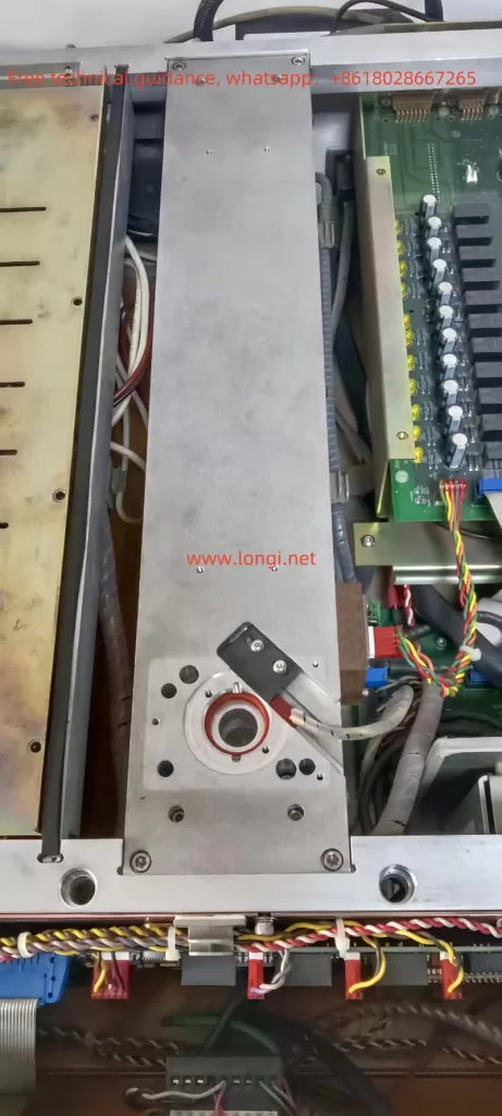
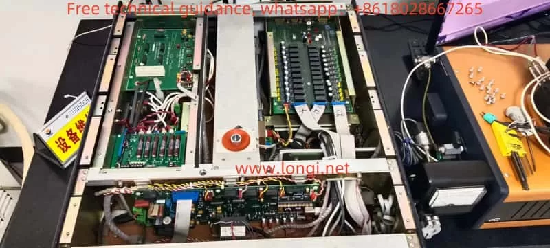
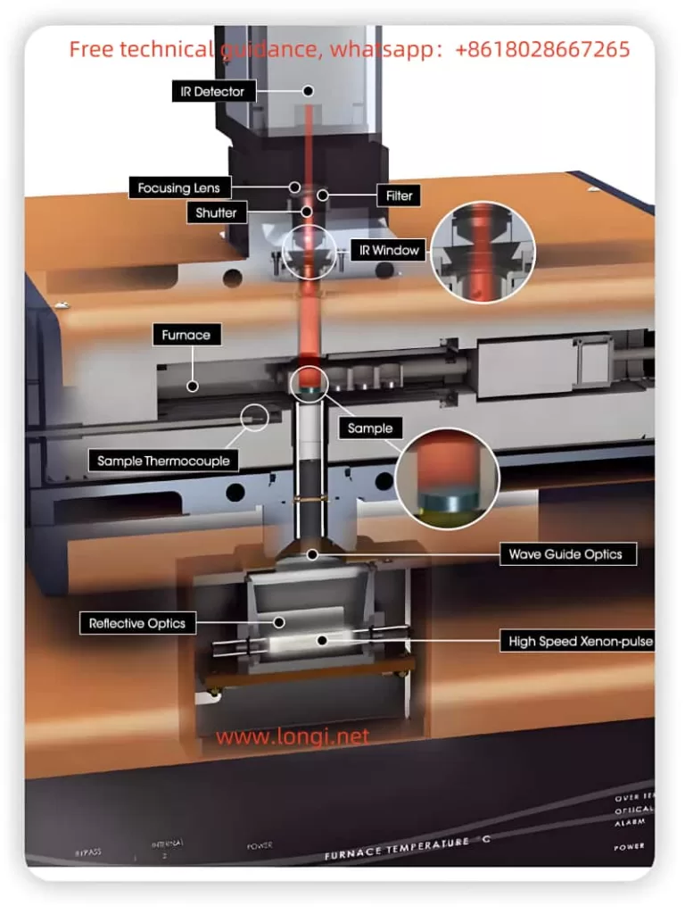
The TA Pulse Laser Thermal Conductivity Tester DLF-1 uses high-precision laser pulse heating technology to accurately measure the thermal diffusion time of materials, thereby calculating thermal conductivity, thermal diffusivity, and other physical parameters. The device is compact and easy to operate, suitable for various materials, including metals, ceramics, composites, and liquids.

Key technical specifications include:

  • Laser pulse energy: up to several millijoules
  • Measurement range: thermal conductivity of materials from room temperature to high temperature
  • Data acquisition accuracy: up to 0.1%
  • Measurement time: typically from milliseconds to a few seconds

2. Pre-Operation Preparation

Before using the TA Pulse Laser Thermal Conductivity Tester DLF-1, users should ensure the following:

  1. Check the Device Appearance
    Confirm that the external appearance of the device is undamaged and that the laser and detector components are in good condition.
  2. Power Connection
    Ensure the device is connected to a stable power source, and the voltage meets the device’s requirements. Use the supplied power cable and avoid replacing it with an unauthorized one.
  3. Install the Sample
    According to the sample installation guidelines in the user manual, ensure the sample is placed on the test platform and secured properly. The sample’s surface should be flat and smooth to ensure uniform laser irradiation.
  4. Calibration
    It is recommended to calibrate the device before the first use or after it has been idle for an extended period. Follow the calibration procedure in the user manual to ensure accurate test results.
Actual Measurement Curve of Thermal Conductivity Meter

3. Operating Procedure

  1. Power On and Initialization
    Turn on the device. The device will perform a self-check and automatically start the operating interface. Once the self-check is completed, the main interface will appear.
  2. Select Test Mode
    Depending on the sample type (e.g., solid, liquid, or gas), select the appropriate test mode. Different materials may require different laser pulse intensity and detector sensitivity.
  3. Set Test Parameters
    Set the test parameters based on the sample’s properties, including laser pulse energy, test duration, scanning rate, etc. The system provides automatically recommended parameter settings, but users can manually adjust them according to specific requirements.
  4. Start the Test
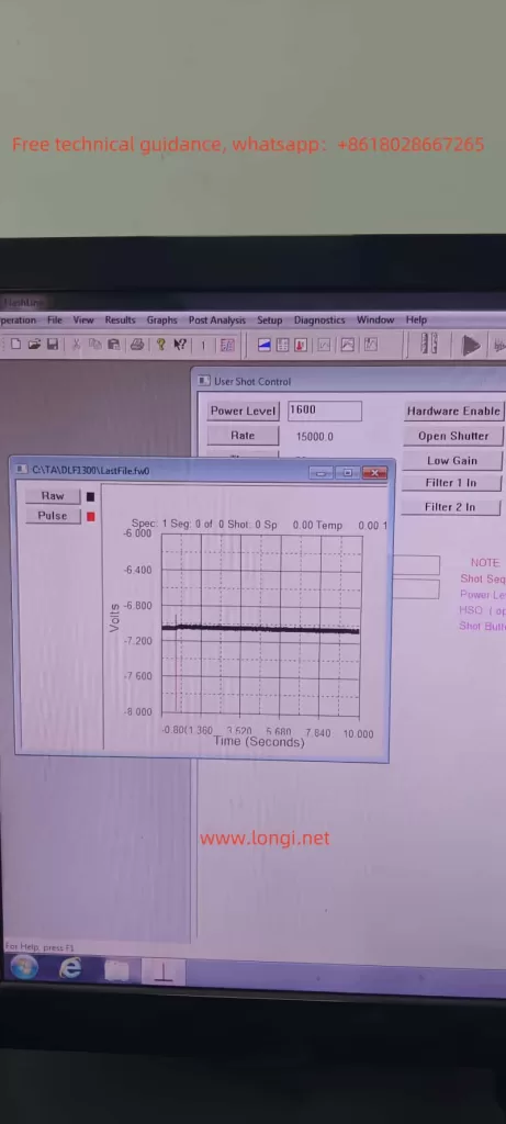
    Click the “Start Test” button. The laser pulse will irradiate the sample surface, and the device will record the temperature changes during the thermal diffusion process, calculating thermal conductivity and other thermal properties.
  5. View and Save Data
    After the test is completed, the system will automatically generate a test report. Users can view the results and choose to save the data. It is recommended to regularly save the test data for future analysis and comparison.

4. Precautions and Usage Details

  1. Laser Safety
    Laser pulses have a certain amount of radiation energy. When operating the device, users should wear appropriate laser protective glasses and avoid direct exposure to the laser beam.
  2. Environmental Control
    Temperature and humidity fluctuations in the test environment can affect the results. Keep the testing environment temperature stable and avoid strong air currents and temperature variations.
  3. Sample Preparation
    The surface condition of the sample has a significant impact on the results. Ensure the sample surface is free of oil, dust, or any substances that could affect the light irradiation. For highly reflective materials, use a light-absorbing agent to enhance absorption.
  4. Operator Training
    Users should receive training on operating the device before use, understanding its basic functions and operation methods to avoid incorrect operation leading to errors or device damage.

5. Maintenance and Care

To ensure the long-term stable operation of the TA Pulse Laser Thermal Conductivity Tester DLF-1, users should perform regular maintenance and care:

  1. Regular Cleaning
    Clean the exterior and optical components of the device with a soft, lint-free cloth. Avoid using chemical cleaners to prevent damaging the surface and optical elements.
  2. Check the Laser System
    The laser emitter is one of the core components of the device. Periodically check the laser output power to ensure it is in normal working condition. If the laser output is abnormal, contact the manufacturer for inspection and repair.
  3. Maintain the Cooling System
    Ensure that the cooling system of the device is functioning properly. For long-term use, check whether the cooling fluid needs to be replaced to ensure stable system temperatures.
  4. Software Updates
    Periodically check and update the device’s operating software to ensure the latest version is in use, improving functionality and performance.

6. Troubleshooting and Handling

During operation, users may encounter some common faults. Below are some common issues and troubleshooting methods:

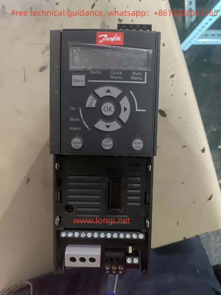
  1. Device Does Not Start
    • Check the power connection to ensure it is stable and the power plug and cable are intact.
    • Check if the fuse has blown and replace it if necessary.
  2. Test Data Is Inaccurate
    • Check if the laser pulse energy is suitable for the current sample.
    • Ensure the sample surface is clean and recalibrate the device.
    • Check if the temperature sensor is working properly.
  3. Laser Output Abnormal
    • Check if the laser emitter is obstructed or damaged.
    • Contact the manufacturer for inspection and replacement of the laser module.

By following the above steps, users can better understand the operation process of the TA Pulse Laser Thermal Conductivity Tester DLF-1 and effectively handle common faults. Regular maintenance and attention to usage details will help extend the device’s lifespan and ensure the accuracy and reliability of test results.


Posted on

TA Pulsed Laser Thermal Conductivity Instrument DLF-1300 Waveform Analysis and Maintenance Case Study

Abstract

The pulsed laser thermal conductivity instrument (Laser Flash Apparatus) is a widely used high-precision tool in material thermal property research, employed to measure the thermal diffusivity and thermal conductivity of materials. This paper takes the DLF-1300 model pulsed laser thermal conductivity instrument produced by TA Instruments as an example to delve into its waveform analysis methods. Additionally, through an actual maintenance case, it analyzes common fault causes and maintenance procedures. The aim is to provide a scientifically rigorous reference for technicians involved in the operation and maintenance of this instrument.

The laser part of TA pulse laser thermal conductivity meter DLF-1

Introduction

Thermal properties such as thermal diffusivity and thermal conductivity are of significant importance in materials science and engineering applications. The pulsed laser thermal conductivity method has become a common approach for studying these parameters due to its high precision and rapid measurement capabilities. The DLF-1300 pulsed laser thermal conductivity instrument from TA Instruments is an advanced measurement device widely used in both research and industrial fields. However, as usage time increases, the instrument may encounter various faults that can affect the accuracy of measurement results. Therefore, mastering waveform analysis and fault maintenance methods is crucial for ensuring the reliability of experimental data.

Internal diagram of TA pulse laser thermal conductivity meter DLF-1

Working Principle of the Pulsed Laser Thermal Conductivity Instrument DLF-1300

The DLF-1300 pulsed laser thermal conductivity instrument operates by emitting short laser pulses to irradiate the sample surface, thereby generating a thermal pulse within the sample. The thermal pulse propagates along the sample’s thickness direction, and a detector (typically an infrared detector) records the temperature change of the sample over time. By analyzing the temperature-time response curve (waveform), the material’s thermal diffusivity and thermal conductivity can be calculated.

Main Components

  1. Laser Pulse Source: Generates high-energy, short-duration laser pulses to excite the sample.
  2. Sample Stage: Secures the sample and ensures accurate positioning of the laser and detector.
  3. Detector: Typically a fast-response infrared detector used to record temperature changes.
  4. Data Acquisition System: Collects the detector signals in real-time and transmits them to a computer for processing.
  5. Optical System: Includes lenses, filters, and other components to guide and adjust the laser and detector light paths.

Waveform Analysis

Waveform analysis is the core part of data processing in pulsed laser thermal conductivity instruments. Precise analysis of the temperature response curve allows for the determination of the material’s thermal diffusivity and thermal conductivity. The following are the basic steps of waveform analysis:

1. Data Acquisition

After the laser pulse irradiates the sample, the detector records the temperature change of the sample surface over time. Ideally, the temperature curve should display a clear rising pulse followed by a gradual stabilization.

2. Baseline Correction

Due to environmental temperature fluctuations and device noise, the acquired temperature curve needs baseline correction to eliminate the influence of background signals.

3. Pulse Identification

Identify the position of the excitation pulse in the temperature curve and its characteristic parameters, such as pulse amplitude and rise time.

4. Calculation of Thermal Diffusivity

Based on the sample’s geometric parameters and the pulse response curve, apply thermal conduction models to calculate the material’s thermal diffusivity. Common models include the semi-infinite body model and the finite thickness model.

5. Calculation of Thermal Conductivity

Using the thermal diffusivity along with the known material density and specific heat capacity, further calculate the material’s thermal conductivity.

Maintenance Case Study

Fault Description

A customer reported that their 2013 model TA DLF-1300 pulsed laser thermal conductivity instrument was producing distorted test results. Specifically, the detection waveform was abnormal, and the detector was not receiving effective signals, leading to inaccurate measurements. Manufacturer’s maintenance personnel initially diagnosed the fault as a damaged laser causing abnormal energy emission.

Abnormal Waveform Analysis

Based on the three images provided by the customer, the first image displayed an abnormal temperature response curve. Under normal circumstances, the temperature curve should show a rapid rise following the laser pulse, then gradually stabilize. However, the customer’s waveform exhibited a flat signal lacking the expected rising pulse, indicating that the detector failed to capture sufficient thermal excitation signals.

Possible Causes of Abnormal Waveform

  1. Insufficient Laser Output: The laser pulse energy is inadequate to effectively excite the sample.
  2. Optical System Failure: The laser beam is not properly focused or is obstructed, preventing energy transfer to the sample.
  3. Detector Issues: The detector’s sensitivity has decreased or there are connection faults, preventing accurate signal reception.
  4. Electronic System Faults: Problems with the data acquisition system or control circuits affecting signal recording.
Fault waveform of TA pulse laser thermal conductivity meter DLF-1

Maintenance Procedures

Based on the manufacturer’s technical personnel’s initial judgment that the fault originated from abnormal laser output, the following specific maintenance steps were undertaken:

1. Preliminary Inspection

  • Visual Inspection: Check for obvious external damage to the laser, such as cracks or burn marks.
  • Connection Inspection: Ensure that the laser is firmly connected to the optical system and control circuits, with no loose or broken connections.

2. Laser Testing

  • Power Testing: Use a power meter to measure the laser’s output power and compare it to the normal range.
  • Pulse Characteristic Testing: Examine the laser pulse’s amplitude, frequency, and duration to ensure they meet instrument specifications.

3. Optical System Inspection

  • Laser Beam Path Inspection: Confirm that the laser beam path from the laser to the sample is unobstructed, free from dust or obstacles.
  • Lens and Filter Inspection: Clean or replace any optical components, such as lenses and filters, that may be contaminated or damaged.

4. Detector Testing

  • Sensitivity Testing: Verify the detector’s sensitivity to ensure it can effectively capture temperature changes.
  • Connection Testing: Ensure that connections between the detector and the data acquisition system are normal and free from signal interference.

5. Electronic System Inspection

  • Power Supply Check: Confirm that the power supply to the laser and detector is stable without voltage fluctuations.
  • Control Circuit Testing: Use an oscilloscope and other instruments to test the control circuit signals, ensuring normal operation.

6. Replacement and Calibration

  • Laser Replacement: If the laser is confirmed to be damaged, replace the laser module with a new one.
  • System Calibration: After replacing the laser, perform a comprehensive calibration of the thermal conductivity instrument to ensure measurement accuracy.

Maintenance Case Summary

In this maintenance case, through waveform analysis, the technical personnel confirmed that insufficient laser output was the primary cause of distorted measurement results. After replacing the damaged laser and recalibrating the instrument, the waveform returned to normal, and the measurement results became accurate. This case illustrates the critical role of waveform analysis in fault diagnosis of pulsed laser thermal conductivity instruments. Timely and accurate maintenance can effectively restore the instrument’s normal functionality.

Common Faults and Preventive Measures

Common Faults

  1. Laser Failures: Including decreased output power and unstable pulses.
  2. Optical System Contamination: Contamination of optical components like lenses and filters, affecting laser transmission.
  3. Decreased Detector Sensitivity: Aging or damaged detectors leading to inaccurate signal capture.
  4. Electronic System Faults: Issues with the data acquisition system or control circuits affecting signal processing.

Preventive Measures

  1. Regular Maintenance: Periodically inspect and clean the optical system to ensure the laser beam path is clean and unobstructed.
  2. Device Calibration: Regularly calibrate the instrument to maintain measurement accuracy.
  3. Environmental Control: Maintain a stable working environment for the instrument, avoiding temperature and humidity fluctuations that may affect device performance.
  4. Proper Operation: Follow the manufacturer’s operation manual correctly to prevent human error from causing device damage.

Conclusion

The TA DLF-1300 pulsed laser thermal conductivity instrument is a high-precision tool for measuring thermal properties of materials, with waveform analysis playing a crucial role in fault diagnosis and maintenance. Through an actual maintenance case, this paper detailed the process of waveform analysis and maintenance, providing valuable references for related technicians. Additionally, it emphasized the importance of regular maintenance and proper operation to extend the device’s lifespan and ensure the accuracy of measurement data.

In the future, with continuous technological advancements, pulsed laser thermal conductivity instruments will further enhance their measurement precision and stability. Technicians must continually learn and master new maintenance technologies to adapt to instrument updates, ensuring greater contributions in scientific research and industrial applications.

Posted on

Danfoss VLT® AutomationDrive FC 360 Series User Manual Operation Guide

The Danfoss VLT® AutomationDrive FC 360 series is a powerful and versatile frequency converter suitable for a wide range of industrial control applications. This article will provide a detailed operation guide for this series of frequency converters, covering the control panel functions, parameter operations, terminal control, and fault code handling.

FC360 front image

I. Control Panel Function Introduction

The Danfoss VLT® AutomationDrive FC 360 series offers two types of control panels: the Numeric Local Control Panel (NLCP) and the Graphical Local Control Panel (GLCP), to meet the needs of different users.

1.1 Basic Control Panel Operations

  • Numeric Local Control Panel (NLCP):
    • Display: Shows current operating parameters and status.
    • Menu Key: Switches between status menu, quick menu, and main menu.
    • Navigation Keys and Indicators: Used for parameter selection and value adjustment, with indicators showing the converter status.
    • Operation Keys: Including [Hand On], [Auto On], [Reset], etc., for manual start, automatic start, and reset operations.
  • Graphical Local Control Panel (GLCP):
    • Similar functions to NLCP but with a larger display for richer information and multi-language support.
FC360 side image

1.2 Parameter Copying and Restoration

  • Parameter Copying:
    1. Upload parameters from Converter A to the control panel: On Converter A, enter the main menu, select “LCP Copy” function, and upload parameters to LCP.
    2. Download parameters from the control panel to Converter B: On Converter B, enter the main menu, select “LCP Copy” function, and download parameters from LCP to the converter.
  • Parameter Initialization:
    Enter the main menu, select the “Operating Mode” parameter, set it to “Initialize” and execute, or reset parameters to factory defaults.
  • Encryption and Parameter Level Settings:
    Protect parameters from unauthorized changes by setting a password (parameter 0-60). Additionally, parameters 0-10 and 0-11 can be used to set the validity and editing permissions of different menus.
  • Compressor Control Parameter Settings:
    Adjust startup parameters (e.g., 1-75 Startup Speed, 1-76 Startup Current), stop parameters (e.g., 1-80 Stop Function), and acceleration/deceleration times (e.g., 3-41 Ramp 1 Acceleration Time) according to compressor application requirements.
Danfoss FC-360 series frequency converter basic wiring diagram

II. Terminal Forward/Reverse Control and External 4-20mA Frequency Setting

2.1 Forward/Reverse Control

  • Wiring:
    • Forward Control: Connect the control signal to terminal 18 (Digital Input [8] Start).
    • Reverse Control: Connect the control signal to terminal 19 (Digital Input [10] Reverse).
  • Parameter Settings:
    • Enter the Digital Input parameter group (5-1*), and set the functions of terminals 18 and 19 to start and reverse, respectively.

2.2 External 4-20mA Frequency Setting

  • Wiring:
    • Connect the external 4-20mA signal to terminal 53 or 54 (depending on the analog input configuration).
  • Parameter Settings:
    1. Enter the Analog Input parameter group (6-1* or 6-2*), and configure terminal 53 or 54 as a current input mode.
    2. Set the minimum and maximum values for the analog input (e.g., 6-10 Terminal 53 Low Voltage, 6-11 Terminal 53 High Voltage), as well as the corresponding feedback or reference value.
    3. In the Reference parameter group (3-1*), select the external analog input as one of the reference sources.

III. Fault Code Handling

The Danfoss VLT® AutomationDrive FC 360 series provides extensive fault codes to help users quickly locate and resolve issues.

  • Common Fault Codes and Meanings:
    • Alarm 14: Earth Fault: Output phase is discharging to earth through the cable between the motor and the converter or the motor itself.
    • Alarm 16: Short Circuit: Short circuit occurs in the motor or motor circuit.
    • Alarm 30: Motor Phase U Missing: Motor U phase is missing between the converter and the motor.
    • Alarm 61: Feedback Error: Deviation exists between the calculated speed and the speed measurement value from the feedback device.
  • Fault Handling:
    • Refer to the fault diagnosis section in the user manual based on the fault code, check the corresponding circuit connections, motor status, and parameter settings.
    • After resolving the fault, perform a reset operation through the control panel or an external reset signal to restore normal operation of the converter.

IV. Conclusion

The Danfoss VLT® AutomationDrive FC 360 series user manual provides a comprehensive operation guide, covering control panel functions, parameter operations, terminal control, and fault code handling. By mastering these operation guides, users can better use and maintain the frequency converter, ensuring its stable and reliable operation in various industrial control scenarios. In practical applications, users should also flexibly adjust parameter settings and control strategies based on specific application requirements and field environments to achieve optimal control effects.

Posted on

User Manual Guide for Hilectro Hi2xx Series Servo Drives

The Hilectro Hi2xx series servo drives are high-performance AC servo drives specifically designed for injection molding machines. This manual aims to provide users with a detailed operation guide, including product overview, safe operation, mechanical installation, electrical connection, parameter setting, troubleshooting, and more.

Function diagram of Hi2xx servo control panel

Product Overview

The Hilectro Hi2xx series servo drives are engineered to deliver precision control and high efficiency, making them ideal for the demanding applications of injection molding machines. These drives come with advanced features such as multiple communication protocols, rich I/O interfaces, and robust protection mechanisms to ensure reliable and stable operation.

Safety Precautions

General Safety Instructions:

  • The drives contain voltages that can be lethal. Always ensure safe and correct operation to minimize risks to personal safety and equipment.
  • During transportation, installation, and storage, prevent physical damage to the drives. Do not remove or bend the components and covers.
  • Store the drives in their original packaging and avoid exposing them to humid, high-temperature environments or direct sunlight for prolonged periods.

Operational Safety:

  • Before powering on, check that the power voltage matches the drive’s rated voltage, ensure correct wiring of inputs and outputs, and inspect for any short circuits. Always cover the drive before powering on.
  • During operation, avoid touching the heat sink or discharge resistors. Non-technical personnel should not detect signals while the drive is running.
  • After powering off, do not perform parameter storage operations as the capacitors may still hold high voltage for up to 5 minutes.

Mechanical Installation

Installation Environment:

  • Choose an installation location with good ventilation and away from sources of heat, vibration, and dust.

Installation Space and Direction:

  • Ensure adequate space around the drive for heat dissipation. Refer to the manual for specific spacing requirements based on the drive’s power rating.
  • Install the drive vertically to facilitate heat dissipation. If multiple drives are installed, use a side-by-side arrangement.
Hi260HI262 servo standard wiring diagram

Electrical Connection

System Peripheral Connection:

  • Connect the drive to the surrounding machinery using appropriate devices such as circuit breakers, contactors, input reactors, and filters to ensure safe and reliable operation.

Main Circuit Wiring:

  • Refer to the wiring diagrams in the manual for connecting the main circuit terminals. Use the recommended copper wire size based on the drive’s power rating.
  • Ensure that the grounding terminal (PE) is reliably grounded with a resistance value less than 10Ω.

Control Circuit Connection:

  • Connect the control circuit wires according to the control board terminal layout. Pay attention to the signal levels and wiring requirements of each terminal.

Parameter Setting

The Hi2xx series servo drives provide a wide range of parameters for users to configure according to their specific needs. These parameters can be divided into several groups, such as Running Parameters (RU), Application Parameters (AP), Protection Parameters (PN), Motor Parameters (DR), etc.

Commonly Used Parameters:

  • RU.01: Target Speed 1 (unit: r/min)
  • AP.00: Command Source (e.g., 0: Terminal + Operator, 1: Terminal, 2: Bus)
  • AP.01: Speed Command Source (e.g., 0: Local, 1: Analog Input 1, 2: Analog Input 2)
  • PN.00: Motor Overload Protection Enable (0: Disable, 1: Enable)
  • DR.02: Motor Rated Power (unit: kW)

To set these parameters, users can use the built-in operation panel or connect to the drive via a computer using communication interfaces such as CAN or EtherCAT.

Troubleshooting

The manual provides detailed descriptions and troubleshooting methods for common faults and warnings. For example:

Fault Code Er053 (Drive Undervoltage):

  • Possible Causes: Input power voltage is too low or fluctuates greatly.
  • Solutions: Check the input power voltage and ensure it meets the drive’s requirements. If the voltage fluctuates, consider adding a voltage stabilizer.

Warning Code 18 (Drive Undervoltage Warning):

  • Solutions: Monitor the input power voltage and take necessary measures to stabilize it.

Conclusion

The Hilectro Hi2xx series servo drives offer advanced performance and flexibility, making them an excellent choice for injection molding machine applications. By following this user manual guide, users can safely and effectively install, configure, and troubleshoot these drives to achieve optimal performance. Always refer to the manual for detailed information and specifications when performing any operation on the drives.

Posted on

User Guide for ABB DCS550 Series DC Drives

I. Functions of the DCS550 Control Panel and Local Start/Speed Adjustment

1.1 Control Panel Overview The DCS550 control panel (DCS Control Panel) is used for monitoring, operation, and parameter configuration of the drive. Its main features include:

  • Start/Stop Button: Used to start or stop the drive.
  • LOC/REM Button: Switches between Local (LOC) and Remote (REM) control modes.
  • Navigation and Confirm Keys: Used for navigating parameter menus and adjusting settings.
  • Display Screen: Displays operational status, alarm messages, and parameter values.
  • Quick Menu: Provides quick access to key parameter settings and fault diagnostics.
DCS550 physical terminal wiring diagram

1.2 Local Start and Speed Adjustment

  • Ensure the drive is in Local mode (display shows “L”).
  • Press the Start button to run the drive.
  • Use the navigation keys to adjust the speed setpoint.

1.3 Field Circuit Parameter Configuration

  • The field voltage output can be measured across the F+ and F- terminals. Set the following parameters based on the motor’s rated values:
    • FldCtrlMode (44.01): Configure the field control mode as “Automatic” or “Constant Voltage.”
    • FldMaxCur (44.02): Set the maximum field current.
    • FldVoltNom (44.03): Set the nominal field voltage.

1.4 Armature Circuit Parameter Configuration

  • Key parameters for the armature circuit include:
    • ArmVoltMax (43.01): Set the maximum armature voltage.
    • ArmCurrMax (43.02): Set the maximum armature current.
    • RampUp/RampDown (42.01/42.02): Configure acceleration and deceleration times for current and speed.
DCS550 labeled wiring diagram

1.5 Speed Feedback Parameter Configuration

  • Speed feedback can be provided via encoder signals or analog signals:
    • SpeedRefSel (20.02): Select the speed reference signal source.
    • EncoderPPR (45.03): Set the pulses per revolution (PPR) for the encoder.

1.6 Auto-Tuning of Parameters

  • Follow these steps for parameter auto-tuning:
    1. Ensure the motor and load are properly connected.
    2. Access the auto-tuning menu and enable AutoTune (22.01).
    3. The system will automatically adjust control parameters and display “OK” upon completion.

1.7 Fan Parameter Configuration

  • Fan control can be enabled or disabled using parameter MotFanCtrl (10.06).
  • FanTest (10.07): Test the fan to ensure proper operation.
  • FanCtrlMode (10.08): Select “Automatic” or “Continuous” control mode.

II. How to Achieve Forward and Reverse Control in Remote Mode

2.1 Wiring Instructions

  • Forward/Reverse Control Signals:
    • Connect the forward and reverse signals to DI1 and DI2 terminals on X4 (used for forward and reverse operations, respectively).
    • If an external emergency stop is required, connect the signal to DI5.
  • Speed Reference Signal:
    • Use an analog input and connect the speed reference signal to AI1 on X2.

2.2 Parameter Configuration

  • Remote Control Mode:
    • Set CommandSel (10.01) to “MainCtrlWord” to enable remote control commands.
  • Forward/Reverse Logic:
    • Configure RevEnable (20.03) to allow reverse operation.
    • Assign forward/reverse input signals to DI1/DI2.
  • Speed Reference Configuration:
    • Set Ref1Sel (11.03) to AI1 for speed reference input.
  • Acceleration/Deceleration Times:
    • Adjust RampUp (42.01) and RampDown (42.02) as needed for the application.

Physical image of DCS550

III. Fault Codes, Their Meanings, and Solutions

The DCS550 displays fault codes to indicate abnormal conditions. Below are common fault codes and their troubleshooting methods:

3.1 Common Fault Codes

  • F001: Overcurrent Fault
    • Cause: Armature current exceeds the maximum set value.
    • Solution:
      • Check if the motor load is too heavy.
      • Verify the correctness of the armature circuit wiring.
      • Decrease acceleration/deceleration times.
  • F002: Overvoltage Fault
    • Cause: Armature voltage exceeds the allowable range.
    • Solution:
      • Check the stability of the power supply voltage.
      • Increase the capacity of the DC power filter.
  • F003: Encoder Fault
    • Cause: Encoder signal lost or abnormal.
    • Solution:
      • Verify encoder wiring and power supply.
      • Check if the parameter EncoderPPR (45.03) is correctly configured.
  • F004: Field Overcurrent
    • Cause: Field circuit current exceeds the set value.
    • Solution:
      • Inspect the wiring of the field circuit.
      • Verify that the field parameters match the motor specifications.
  • F005: Fan Fault
    • Cause: The fan failed to start or stopped unexpectedly.
    • Solution:
      • Check the fan’s power supply and terminal connections.
      • Use FanTest (10.07) to test the fan’s functionality.

3.2 General Fault Troubleshooting Recommendations

  • Check the alarm messages on the control panel and note the fault codes.
  • Refer to the troubleshooting section of the user manual for detailed instructions.
  • Use the DriveWindow Light software to access detailed fault diagnostics and suggestions.

IV. Conclusion

This guide provides a detailed overview of the operation, parameter configuration, remote control, and fault troubleshooting of the ABB DCS550 DC drive. During use, consider the following key points:

  1. Ensure electrical wiring complies with the manual to avoid errors.
  2. Familiarize yourself with the control panel functions and adjust parameters to meet application needs.
  3. Regularly inspect the equipment’s operational status and promptly address alarm messages.

For complex issues, contact ABB technical support or refer to the relevant sections of the user manual for further diagnosis and resolution.

Posted on

User Guide for Delixi Inverter CDI-EM60/CDI-EM61 Series Manual

I. Introduction to Operation Panel Functions

The Delixi Inverter CDI-EM60/CDI-EM61 series is equipped with an intuitive and user-friendly operation panel, enabling users to easily set and adjust parameters.

CDI-EM60 and EM61 series frequency converter operation panel function diagram

Key Components of the Operation Panel

  1. Display Screen: Displays various operation parameters, status indicators, and error messages.
  2. Function Keys:
    • RUN: Starts the inverter.
    • STOP: Stops the inverter.
    • JOG: Enables jogging (inching) operation.
    • PROG: Enters programming mode for parameter adjustment.
    • ESC/RESET: Exits programming mode or resets errors.
    • ▲/▼: Adjusts parameter values.
    • ▶/◀: Navigates through menus.

Basic Operations

  1. Power On: Ensure the inverter is properly powered on.
  2. Navigation: Use the ▶/◀ keys to navigate through different menus and parameters.
  3. Value Adjustment: Use the ▲/▼ keys to adjust parameter values.
  4. Save & Exit: Press the ESC key to save changes and exit programming mode.

II. Using Simplified Internal Relay Programming Function

The Simplified Internal Relay Programming function allows users to perform basic logical operations using the inverter’s internal relays.

Steps to Configure

  1. Enter Programming Mode: Press the PROG key to enter programming mode.
  2. Navigate to Relay Control Parameters: Use the ▶/◀ keys to navigate to the relay control parameters (P3.2 group).
  3. Set Relay Logic:
    • P3.2.00: Set the control logic for each relay (M1-M5).
    • P3.2.01-P3.2.06: Configure the input conditions for each relay.
    • P3.2.07-P3.2.11: Define the output actions for each relay.
  4. Set Delay Times:
    • P3.2.12-P3.2.16: Set the on-delay times for each relay.
    • P3.2.17-P3.2.21: Set the off-delay times for each relay.
  5. Save Settings: Press the ESC key to save changes and exit programming mode.
CDI-EM60 and EM61 series VFD standard wiring diagram

III. Using Internal Timer Function

The Internal Timer function provides users with timing control capabilities.

Steps to Configure

  1. Enter Programming Mode: Press the PROG key to enter programming mode.
  2. Navigate to Timer Control Parameters: Use the ▶/◀ keys to navigate to the timer control parameters (P3.2.22-P3.2.25).
  3. Set Timer Control:
    • P3.2.23: Configure timer start/stop conditions.
    • P3.2.24/P3.2.25: Set the timer duration for Timer 1 and Timer 2.
  4. Set Timer Units:
    • P3.2.23: Select the time units (seconds, minutes, or hours).
  5. Save Settings: Press the ESC key to save changes and exit programming mode.

IV. Using Internal Calculation Module Function

The Internal Calculation Module function enables users to perform simple arithmetic operations and logical judgments.

Steps to Configure

  1. Enter Programming Mode: Press the PROG key to enter programming mode.
  2. Navigate to Calculation Module Parameters: Use the ▶/◀ keys to navigate to the calculation module parameters (P3.2.26-P3.2.39).
  3. Select Operation Type:
    • P3.2.26: Choose the type of operation (addition, subtraction, multiplication, division, comparison, etc.).
  4. Set Input Addresses:
    • P3.2.28/P3.2.29: Specify the input addresses (A and B) for the operation.
  5. Set Scaling Factors:
    • P3.2.30/P3.2.33: Define the scaling factors for the operation results.
  6. Configure Output:
    • Set the output address or action for the calculation result.
  7. Save Settings: Press the ESC key to save changes and exit programming mode.

V. Restoring Parameters to Factory Defaults

To restore the inverter parameters to their factory defaults, follow these steps:

  1. Enter Programming Mode: Press the PROG key to enter programming mode.
  2. Navigate to Parameter Initialization: Use the ▶/◀ keys to navigate to the parameter initialization parameter (P5.0.19).
  3. Select Initialization Option:
    • Set P5.0.19 to “09” to restore factory parameters, excluding motor parameters, calibration parameters, and password parameters.
    • Set P5.0.19 to “19” to restore factory parameters, excluding motor parameters and password parameters.
  4. Confirm Initialization: Press the RUN key to confirm the initialization process. The inverter will restart automatically.
  5. Exit Programming Mode: Press the ESC key to exit programming mode.

By following these guidelines, users can efficiently utilize the advanced features of the Delixi Inverter CDI-EM60/CDI-EM61 series, ensuring optimal performance and reliable operation.

Posted on

SEW Servo MDX60B/MDX61B Series User Guide and Fault F196.4 Meaning and Solutions

The SEW Servo Drives MDX60B/MDX61B series are widely used in automation control systems, known for their high performance and reliability, meeting the needs of various industrial applications. This guide will provide a detailed introduction to the usage, parameter settings, common faults, and troubleshooting methods of this series, with a focus on explaining the meaning of fault code F196.4 and its resolution.

On site maintenance of SEW servo

1. SEW Servo Operation Panel DBG60B Features

The SEW Servo Drives MDX60B/MDX61B series are equipped with the DBG60B operation panel, which provides an easy-to-use interface for monitoring and configuring the drive parameters.

Main Features:

  • Operating Status Display: The operation panel can display the current status of the servo drive, including alarms, operating parameters, and other critical information.
  • Parameter Settings: Users can set and adjust various parameters to customize the operation of the drive for specific applications.
Setting “Heat Sink Temperature” and “Operating Time”:
  1. On the DBG60B panel, press the “MENU” button to enter the parameter setting mode.
  2. Navigate to the “Parameters” menu and find the monitoring options for “Heat Sink Temperature” and “Operating Time.”
  3. Enable these parameters for display.
  4. After setting, press the “Confirm” button to save the settings. From then on, the operation panel will show the heat sink temperature and operating time, allowing users to monitor the drive’s operating conditions.
Restoring Factory Default Parameters:
  1. On the DBG60B panel, press the “MENU” button to enter the parameter setting mode.
  2. Select “Restore Factory Settings” from the menu.
  3. Confirm the restoration of factory settings, and the system will reset all parameters to their default values. This is useful for initializing the device or correcting configuration errors.
Setting Password and Locking Parameters:
  1. In the “Menu” options, select “Password Settings.”
  2. Enter the default password (usually “0000”), then set a new password.
  3. Enable “Lock Parameters” to prevent unauthorized modification of critical settings. This step is crucial for preventing accidental changes and ensuring the safety of the equipment.
SEW-MDX6061 Standard Wiring Diagram

2. Setting External Terminal Forward/Reverse and External Potentiometer (Analog) for Frequency Control

The SEW Servo MDX60B/MDX61B series supports controlling forward/reverse rotation and adjusting the speed via an external potentiometer or other analog input signals. This is useful for manual speed and direction control in various applications.

Wiring Requirements:
  • Forward/Reverse Control: Use digital input terminals (e.g., X10-X12) to connect external pushbuttons or switches for forward and reverse control.
    • For example, connect a switch between terminals X10 and X11 to implement forward/reverse control.
  • Analog Speed Control via Potentiometer: Use the analog input terminal (e.g., X13) to connect an external potentiometer (10kΩ) or other analog devices that provide a 0-10V or 4-20mA signal to control the speed.
    • Terminal X13 is used for the analog input to set the motor speed.
Parameter Settings:
  1. Setting External Forward/Reverse:
    • In the parameter menu, set the “Control Mode” to “External Control.” Map the input terminals X10-X12 to forward/reverse control functions.
    • Set the input signal correctly (e.g., X10 for forward, X11 for reverse).
  2. Setting Analog Potentiometer for Speed Control:
    • In the parameters, set the “Speed Control Mode” to “Analog Input Speed Control” and select the appropriate input terminal (e.g., X13).
    • Ensure the correct analog signal range (e.g., 0-10V or 4-20mA) is selected to ensure accurate speed control.
SEW MDX61B physical picture

3. Common Fault Codes in SEW Servo Drives and Solutions

The SEW Servo MDX60B/MDX61B series may show several common fault codes, including but not limited to:

  • F0001 – Overload Protection: This error indicates that the load on the servo motor exceeds its rated capacity, triggering the protection mechanism.
    • Solution: Check if the load is too heavy. Adjust the load or reduce the drive output power accordingly.
  • F0102 – Motor Overheating: If the motor temperature exceeds the set threshold, this fault is triggered.
    • Solution: Check the cooling system, ensure proper airflow, and remove any obstructions that may affect cooling.
  • F0203 – Encoder Signal Loss: When the encoder signal is lost or unstable, the drive cannot get accurate position feedback.
    • Solution: Inspect the encoder connection, ensuring that the signal wires are intact and not damaged.
F196.4 FAULT

4. Fault F196.4 Meaning and How to Repair It

F196.4 is a fault indicating an issue with the “Inverter Coupling Reference Voltage”, specifically a defective inverter coupling. This fault typically occurs when the reference voltage in the inverter’s coupling circuit is unstable or fails.

F196.4 Fault Analysis:
  • Fault Description: The F196.4 fault code generally indicates that the coupling module within the inverter cannot function properly, failing to generate or maintain the required reference voltage. This leads to abnormal signal transmission, affecting the inverter’s operation.
  • Possible Causes:
    1. Failure of the coupling module’s internal power supply, preventing the generation of reference voltage.
    2. Faulty circuit components (e.g., capacitors, resistors) within the coupling module.
    3. External power supply issues or unstable voltage leading to abnormal reference voltage.
Solution:
  1. Check the Coupling Module: Inspect the coupling module for any visible damage or loose connections.
  2. Measure the Voltage: Use a multimeter or oscilloscope to check the output voltage of the coupling module and ensure it is stable and within the specified range.
  3. Replace Defective Components: If the coupling module or related components are found to be defective, replace them with the correct parts.
  4. Verify Power Supply Stability: Ensure the power supply system is stable and the wiring connections are correct.

If the issue persists after these checks, it is recommended to contact SEW-EURODRIVE technical support for further diagnosis and assistance.


Conclusion

The SEW Servo MDX60B/MDX61B series drives, with their high efficiency and versatile functions, are widely used in industrial automation. The DBG60B operation panel provides an intuitive interface for setting parameters, monitoring status, and making adjustments as needed. Understanding common fault codes and their solutions is essential for maintaining system reliability. In particular, F196.4 indicates a serious issue with the inverter’s coupling reference voltage, which requires immediate attention and repair. By following the troubleshooting steps outlined in this guide, users can ensure the smooth operation and longevity of their servo drive systems.

Posted on

User Manual Guide for SUNYE CM530 Series Frequency Converter

The SUNYE CM530 series frequency converter is a high-performance flux vector control frequency converter widely used in various industrial control applications. This article aims to provide users with a detailed guide covering operation panel functions, terminal wiring and parameter settings, fault code analysis and troubleshooting methods, helping users better use and maintain the frequency converter.

CM530 Operation Panel Function Diagram
I. Introduction to Operation Panel Functions

The operation panel of the CM530 frequency converter integrates multiple functions, including parameter setting, status monitoring, and operation control. Here are the introductions to the main functions:

  1. Restoring Factory Settings:
    • In the stopped state of the frequency converter, enter the parameter setting interface through the operation panel.
    • Select function code F0-28 and set its value to “1”. Then press the confirmation key, and the frequency converter will restore factory settings.
  2. Setting and Resetting Passwords:
    • Setting Password: Select function code F7-49 and set its value to a non-zero value to enable parameter protection. After setting, entering the parameter setting menu again requires a password.
    • Resetting Password: Under password protection, set F7-49 to “0” to disable password protection.
  3. Setting Parameter Protection:
    • Parameter protection is realized through passwords. After setting the password, unauthorized users cannot modify the frequency converter parameters, ensuring the stability and security of device operation.
II. Terminal Forward/Reverse Control and External Potentiometer Speed Regulation

The CM530 frequency converter supports forward/reverse control via terminals and speed regulation using an external potentiometer. The specific wiring and parameter settings are as follows:

  1. Forward/Reverse Control Wiring:
    • Connect the forward control line to the DI1 terminal and the reverse control line to the DI2 terminal.
    • In the parameter setting interface, set F5-00 to “1” (forward operation) and F5-01 to “2” (reverse operation).
  2. External Potentiometer Speed Regulation Wiring:
    • Connect the center tap of the external potentiometer to the GND of the AI1 terminal, and the other ends to AI1 and +10V, respectively.
    • In the parameter setting interface, set F0-06 to “2” (AI1), selecting AI1 as the main frequency source.
  3. Parameter Settings:
    • Adjust parameters such as F0-14 (maximum operating frequency) according to actual needs to meet the speed regulation range requirements.
III. Fault Code Analysis and Troubleshooting Methods

The CM530 frequency converter features comprehensive fault protection functions. When a fault occurs, the corresponding fault code will be displayed on the operation panel. Here are some common fault codes, their meanings, and troubleshooting methods:

  1. Err01: Inverter Unit Protection
    • Meaning: The inverter has encountered a severe fault, such as overcurrent or overvoltage.
    • Solution: Check the motor and load for abnormalities, and inspect the input and output lines of the frequency converter for short circuits or grounding. If the issue cannot be resolved, contact after-sales service.
  2. Err02: Hardware Overcurrent Protection
    • Meaning: The output current of the frequency converter exceeds the rated value.
    • Solution: Check the motor and load for overload, inspect the motor cable for excessive length or poor insulation, and appropriately adjust the frequency converter parameters.
  3. Err03: Hardware Overvoltage Protection
    • Meaning: The DC bus voltage of the frequency converter is too high.
    • Solution: Check the input power supply voltage for being too high and inspect the braking resistor and braking unit for normal operation.
  4. Err13/Err14: Frequency Converter/Motor Overload
    • Meaning: The frequency converter or motor has been overloaded for an extended period.
    • Solution: Check the load for being too large, appropriately adjust the load or increase the motor capacity, and inspect the motor for being blocked or jammed.
IV. Conclusion
CM530 standard wiring diagram

The SUNYE CM530 series frequency converter user manual provides users with comprehensive operation guidance and troubleshooting methods. By proficiently mastering the functions of the operation panel, reasonably setting terminal wiring and parameters, and promptly analyzing and resolving fault codes, users can ensure the stable operation and efficient work of the frequency converter. Additionally, users should regularly perform maintenance and servicing of the frequency converter to extend its service life and improve operational efficiency.

During use, if encountering faults or questions that cannot be resolved, it is recommended to promptly contact the after-sales service team of SUNYE frequency converters for professional technical support and assistance. Through rational use and maintenance, the SUNYE CM530 series frequency converter will bring greater convenience and benefits to users’ industrial production.

Posted on

Operation Guide for Yuanshin Inverter YX300 Series User Manual

The Yuanshin Inverter YX300 series is a high-performance, low-noise inverter widely used in various industrial equipment. This document aims to provide users with an operation guide for this series of inverters, detailing how to control the inverter via its operation panel, how to set password and parameter access restrictions, how to initialize parameters, and how to achieve forward and reverse control via external terminals.

Actual operation picture of YX3000

1. Introduction to the Operation Panel and Basic Control

Operation Panel Function Introduction

The operation panel of the Yuanshin Inverter YX300 series features intuitive controls that allow users to easily monitor and manage the inverter’s operation. The following are the key functions and their corresponding operations:

  • Start/Stop the Inverter:
    • Start: Press the “RUN” button on the operation panel to start the inverter.
    • Stop: Press the “STOP/RESET” button to stop the inverter.
  • Set Frequency Using the Panel Potentiometer:
    • Rotate the potentiometer on the operation panel to adjust the output frequency of the inverter. This method is suitable for manual frequency adjustments during testing or initial setup.

Setting Password and Parameter Access Restrictions

  • Setting a Password:
    1. Press the “MENU” button to enter the parameter setting mode.
    2. Use the arrow keys to navigate to the password setting parameter (typically found in the PF group parameters).
    3. Enter the desired 4-digit password using the numeric keys.
    4. Press “ENTER” to confirm the password.
  • Accessing Restricted Parameters:
    • When attempting to access a restricted parameter, the inverter will prompt for the password. Enter the correct password to proceed.
  • Disabling the Password Function:
    • To disable the password function, simply set the password to “0000” and confirm.

Initializing Parameters

  • Parameter Initialization:
    1. Press the “MENU” button to enter the parameter setting mode.
    2. Navigate to the parameter initialization function (typically P3.01).
    3. Set the parameter to “1” to restore factory default settings.
    4. Press “ENTER” to confirm and initialize the parameters.
YX3000 standard wiring diagram for Yuanxin frequency converter

2. Forward and Reverse Control via External Terminals

Basic Wiring for External Control

To achieve forward and reverse control of the Yuanshin Inverter YX300 series via external terminals, you need to properly wire the control terminals. The following are the basic steps:

  1. Identify the Control Terminals:
    • FWD (Forward): Connect this terminal to a positive signal source to start the inverter in the forward direction.
    • REV (Reverse): Connect this terminal to a positive signal source to start the inverter in the reverse direction.
    • COM (Common): Common ground terminal for both FWD and REV.
  2. Wiring Configuration:
    • Connect the FWD terminal to a switch or relay contact that closes when you want the motor to run forward.
    • Connect the REV terminal to a switch or relay contact that closes when you want the motor to run reverse.
    • Ensure both FWD and REV terminals are connected to the COM terminal.
  3. Parameter Settings:
    • Set the operation command source to external terminals (P0.03 = 1).
    • Configure the frequency input method as desired (e.g., via potentiometer, analog signal, etc.).

Operation Example

  • Forward Operation:
    • Close the contact connected to the FWD terminal.
    • The inverter will start and run the motor in the forward direction.
  • Reverse Operation:
    • Close the contact connected to the REV terminal.
    • The inverter will start and run the motor in the reverse direction.
  • Stopping the Inverter:
    • Open both the FWD and REV contacts.
    • The inverter will stop the motor.

By following this operation guide, users can easily control the Yuanshin Inverter YX300 series via its operation panel and external terminals, setting passwords and parameter access restrictions as needed, and initializing parameters when required. This ensures efficient and secure operation of the inverter in various industrial applications.

Posted on

Siemens Inverter MM440 Series User Guide and Meaning of A503 Warning with Solutions

I. Introduction to MM440 Series Inverter Operating Panel Functions

1.1 Overview of Operating Panels

MM440 PICTURE

The Siemens MM440 series inverter is equipped with operating panels, including the Status Display Panel (SDP), Basic Operating Panel (BOP), and Advanced Operating Panel (AOP). These panels provide an intuitive interface for user interaction with the inverter, enabling monitoring, setting, and control of the inverter’s operation.

1.2 Setting Passwords and Parameter Levels

To prevent unauthorized changes, the MM440 inverter supports parameter locking and password protection. To set passwords and parameter levels, follow these steps:

  1. Enter Parameter Setting Mode: Use the BOP or AOP to press the “P” key to enter parameter setting mode.
  2. Select Password Parameter: Locate and set parameter P0012 (Unlocking of User-Defined Parameters) to your desired password.
  3. Lock Parameters: Set parameter P0011 (Locking of User-Defined Parameters) to 1 to enable password protection.

1.3 Restoring Factory Settings

To restore the inverter parameters to factory settings, follow these steps:

  1. Enter Parameter Setting Mode.
  2. Set P0010=30: Select the restore factory settings function.
  3. Set P0970=1: Confirm the execution of restoring factory settings.

1.4 Using BICO Functionality

The BICO (Binary Interconnect Connection) function allows users to program interconnections between internal signals and input/outputs of the inverter. To use the BICO function, follow these steps:

  1. Enter Parameter Setting Mode.
  2. Set Relevant BICO Parameters: For example, P0701 to P0708 are used to configure the functions of digital inputs, and P0731 to P0733 are used to configure the functions of digital outputs.
  3. Program Interconnection Logic: According to application requirements, use BICO control words and status words to program the desired interconnection logic.

II. Terminal Control and External Potentiometer Speed Regulation

2.1 Terminal Control

The MM440 inverter supports speed control via terminals. To achieve terminal control, follow these steps to set parameters and wiring:

  1. Set Command Source: Set parameter P0700 to 2 to select terminal control mode.
  2. Configure Digital Inputs: Configure parameters P0701 to P0708 as needed to specify the functions of each digital input (such as start, stop, direction control, etc.).
  3. Wiring: Connect external control signals (such as start and stop buttons) to the corresponding digital input terminals.

2.2 External Potentiometer Speed Regulation

An external potentiometer can be used to adjust the output frequency of the inverter, enabling speed regulation. The setup steps are as follows:

  1. Set Frequency Reference Source: Set parameter P1000 to 2 to select analog input as the frequency reference source.
  2. Configure Analog Input: Ensure that analog input AIN1 or AIN2 is correctly configured to receive a 0-10V or 0-20mA speed regulation signal.
  3. Wiring: Connect the output of the external potentiometer to the AIN1 or AIN2 terminal of the inverter, and ensure that the potentiometer is properly powered.
A503 WARNING CODE

III. Meaning of A503 Warning and Solutions

3.1 Meaning of A503 Warning

The A503 warning indicates that the inverter has detected undervoltage limitation, meaning that the DC link voltage is below the allowed minimum value. This can be caused by unstable supply voltage, input power failure, or internal inverter faults.

3.2 Solutions

  1. Check Supply Voltage: Ensure that the input supply voltage is within the allowed range and remains stable.
  2. Adjust Parameters:
    • Increase the ramp-down time (P1121) to reduce voltage drops during braking.
    • If the dynamic buffer function is enabled (P1240=2), adjust relevant parameters (such as P1243, P1245) to optimize performance.
  3. Check Inverter Internals: If the problem persists, it may be necessary to check the internal DC link and capacitors of the inverter for proper function.

3.3 Fault Codes and Meanings

The MM440 inverter has multiple fault codes that indicate different fault conditions. Here are some common fault codes and their meanings:

  • F0001: Overcurrent, usually caused by motor or cable short circuits, mismatched motor power, etc.
  • F0002: Overvoltage, possibly due to excessively high supply voltage or excessive regenerative energy generated during braking.
  • F0003: Undervoltage, indicating that the input supply voltage is below the allowed range.
  • F0004: Inverter overtemperature, usually caused by poor cooling or excessively high ambient temperature.
  • F0011: Motor overtemperature, possibly due to motor overload or poor cooling.

3.4 Fault Solutions

Methods for resolving inverter faults typically include checking the supply voltage, motor and cable connections, cooling system, and internal components of the inverter. Specific steps should be taken based on the indications of the fault code.

IV. Conclusion

This article provides a detailed introduction to the operating panel functions, terminal control and external potentiometer speed regulation setup methods, as well as the meaning and solutions of the A503 warning for the Siemens MM440 series inverter. Additionally, it outlines common fault codes, their meanings, and solutions. With the guidance of this article, users can better understand and utilize the MM440 series inverter to ensure stable equipment operation.