In industrial automation, variable frequency drives (VFDs) play a central role in motor control and energy savings. Among them, the Schneider Electric ATV312 series has gained wide application in medium and small-power motor systems due to its reliability and flexible parameter configuration. However, during long-term operation, users often encounter the ObF fault.
This article provides a systematic explanation of the causes, detection methods, and corrective measures for the ObF fault. It also refers to details in the official ATV312 Programming Manual, giving readers a clear, logical, and practical guide.
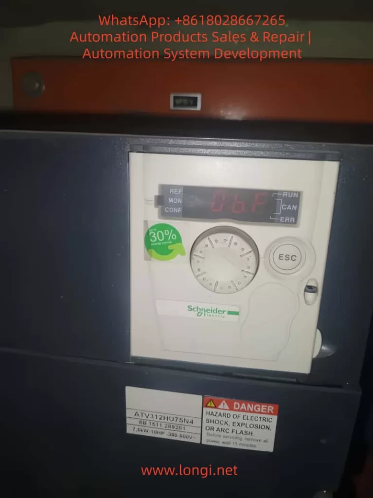
I. Definition of the ObF Fault
On the ATV312 display, ObF stands for Overvoltage Fault.
This means: when the DC bus voltage exceeds its permissible threshold, the drive shuts down and generates a fault alarm to protect internal circuits.
Symptoms include:
Drive display shows “ObF”
Motor stops abruptly
Fault relay outputs a signal
The root cause is the excessive regenerative energy fed back into the DC bus during motor deceleration or braking, which raises capacitor voltage beyond the safe range.
II. Typical Scenarios Leading to ObF
Rapid Deceleration
The motor’s inertia releases kinetic energy into the DC bus.
Common with fans, centrifugal machines, and hoists.
Excessive Supply Voltage
Input supply exceeds the rated range (380–600 V).
Often occurs in weak or fluctuating grids.
Missing or Faulty Braking Resistor
Without a braking resistor or with a damaged unit, the excess energy cannot dissipate.
Unreasonable Parameter Settings
Too short deceleration time (dEC).
Frequent starts and stops causing energy surges.
Mechanical Anomalies
Transmission system back-driving the motor or abnormal loads.
III. Consequences of ObF
Unexpected Downtime – Production line interruption and economic losses.
Electrical Stress – Repeated high bus voltage damages IGBTs and capacitors.
Component Aging – Frequent resets accelerate wear of electronic components.
Thus, preventing ObF is essential for maintaining stable operation.
IV. Diagnostic Process
Check Input Voltage
Ensure voltage is within rated range using a multimeter or power analyzer.
Verify Application Type
Identify whether the load is high inertia.
Inspect Braking Circuit
Confirm resistor installation, capacity, and braking unit health.
Check Parameters
Focus on deceleration time (dEC), braking settings (brA), and motor parameters.
Test Run
Increase dEC and monitor whether the fault reoccurs.
If still present, braking resistor or additional hardware is required.
V. Manual-Based Optimization
According to the ATV312 Programming Manual:
Deceleration Time (dEC)
Factory setting: ~3–5s.
Recommendation: increase to 10–20s for high-inertia loads.
Braking Parameter (brA)
When using a braking resistor, disable slope adaptation (brA=No) to ensure resistor engagement.
Bus Circuit Notes
The PO–PA/+ terminals must remain connected; otherwise, drive circuits may be damaged.
VI. Corrective Actions
1. Software Adjustments (Lowest Cost)
Increase deceleration time (dEC).
Avoid frequent start/stop and emergency stop operations.
Optimize control logic to reduce unnecessary reversals.
2. Hardware Enhancements
Install a braking resistor sized for the drive’s rated power.
Upgrade the resistor if already installed but overheating.
Add an AC line reactor to reduce voltage spikes in weak grid supply.
3. System-Level Solutions
Use regenerative drives or braking chopper modules.
Select a drive model tailored for fan or hoist applications.
VII. Case Studies
Case 1: Fan Application
Drive: ATV312HU75N4 in a cement plant.
Problem: Frequent ObF faults during deceleration.
Findings: dEC set to 5s; no braking resistor installed.
Solution: Extended dEC to 15s, installed 100Ω/2kW resistor.
Result: Fault eliminated, system stabilized.
Case 2: Hoist Application
Drive: ATV312 controlling a mining hoist.
Problem: ObF occurs during heavy-load descent.
Findings: Input voltage normal at 410V; resistor installed but overheated.
Solution: Replaced with higher capacity 75Ω/5kW resistor and added forced air cooling.
Result: Continuous stable operation.
VIII. Preventive Maintenance
Routine Checks
Inspect resistor for overheating or discoloration.
Measure resistance to verify specification.
Parameter Backup
Use Schneider SoMove software to store settings.
Real-Time Monitoring
Add bus voltage monitoring in SCADA systems.
Trigger alarms before faults occur.
Environmental Conditions
Ensure adequate cooling and dust removal to prevent derating.
IX. Conclusion
The ObF fault is one of the most common alarms in Schneider ATV312 drives, directly linked to DC bus overvoltage.
Key insights:
Software tuning (increase dEC) is the first corrective measure.
Hardware configuration (braking resistor, reactors) is essential for high-inertia applications.
System-level planning ensures the drive is suited to the operating environment.
By combining parameter optimization, proper hardware sizing, and proactive maintenance, ObF faults can be effectively eliminated, ensuring long-term reliable operation of ATV312 drives.
In modern industrial and commercial sectors, precise weighing is crucial for ensuring product quality, production efficiency, and fair trade. As a global leader in weighing solutions, Mettler Toledo’s IND245 Electronic Weighing Instrument (Vehicle Scale Version) stands out with its advanced technology, reliable performance, and flexible application scenarios, making it an ideal choice for vehicle weighing, logistics management, and industrial weighing. Designed specifically for vehicle scales, it supports both analog and digital sensor inputs, catering to scenarios such as truck scales and lorry weighbridges, and handling complex weighing needs from small vehicles to heavy-duty trucks.
This guide, based on the Technical Manual for the Toledo ND245 Electronic Weighing Instrument (Vehicle Scale Version), aims to provide users with a comprehensive and practical operational reference. It will start with the instrument’s principles, features, and specifications, followed by step-by-step instructions on installation and maintenance, daily operation procedures, and parameter settings, concluding with discussions on common faults and their resolution strategies. Through this guide, users will not only be able to get started quickly but also optimize instrument performance for long-term stable operation. Whether you are a first-time user or an experienced engineer, this guide will help you maximize the potential of the IND245 for efficient and accurate weighing management.
The IND245 is designed with a focus on user-friendliness and high reliability. It adopts a modular structure and supports multiple communication interfaces, suitable for a variety of applications ranging from simple weighing to complex vehicle pairing. The manual emphasizes the involvement of professionals in commissioning to avoid safety hazards. This guide will strictly adhere to the principles outlined in the manual, providing original interpretations and expanded explanations to help users apply the IND245 flexibly in real-world environments.
Instrument Principles, Features, and Specifications
Working Principles
The IND245 Electronic Weighing Instrument operates based on precise signal acquisition, processing, and display technologies. It connects to weighing sensors (either analog or digital types) to convert mechanical force into electrical signals, which are then digitized by an A/D converter and ultimately displayed on an LCD screen as weighing results. The core components include the mainboard, A/D conversion module, microprocessor, and display keyboard.
For analog sensors, the IND245 supports sensors with a 350-ohm load resistance and is compatible with sensitivities of 2mV/V and 3mV/V without additional configuration. The sensor converts weight changes into millivolt-level voltage signals, with the mainboard providing a 10V excitation voltage. The A/D converter performs high-speed digital conversion at a sampling rate of 366Hz. The microprocessor applies digital filtering algorithms (such as low-pass filtering and steady-state detection) to eliminate noise, ensuring accuracy within 6000e (verification divisions).
For digital sensors (such as the SLC720 POWERCELL GDD), the instrument uses the RS-422/485 protocol, supporting up to 12 sensors connected via a 300-meter Homerun cable. Digital signals are transmitted directly, avoiding attenuation and interference inherent in analog transmission, thereby enhancing anti-interference capabilities and precision stability. The instrument incorporates a real-time clock (RTC) and an SD/MicroSD card for data backup and Alibi storage, ensuring tamper-proof transaction records.
The overall principle can be summarized as: Sensor → Signal Excitation/Acquisition → A/D Conversion → Digital Filtering/Processing → Display/Output. The vehicle scale version is specifically optimized for paired weighing functions, supporting inbound/outbound operations, automatically calculating net weight, and ensuring positive output through negative net weight correction, suitable for logistics scenarios.
Key Features
The IND245 stands out for its versatility and cost-effectiveness, with key features including:
High Precision and Wide Range: Supports up to 50,000 display divisions with an accuracy of 6000e. Automatic zero tracking (AZM) and multi-range switching ensure accurate measurements from微量 (trace amounts) to heavy loads. Adjustable steady-state detection time (0.3-1 second) enables fast dynamic response, suitable for vehicles quickly mounting the scale.
Flexible Sensor Compatibility: Seamlessly supports 8 analog sensors or 12 digital sensors. The digital version maintains signal integrity over long distances, reducing wiring costs.
Rich Communication and Integration Options: Standard RS-232/422/485 interfaces support SICS protocol, continuous output, and CTPZ commands. Optional interfaces include USB, Ethernet, and DIO (2 inputs, 4 outputs), facilitating integration with PLCs, PCs, or printers. The vehicle scale version includes built-in preset points and a tare library, supporting 100 temporary and 200 permanent tare records.
User-Friendly Interface: A 240×96 dot-matrix LCD display supports Chinese and English switching. The 25-key keyboard includes numeric/alphabetic input and navigation keys, with unique digital shortcuts for accelerated menu navigation. The system row displays DIO status and time, while the information input area supports ID/vehicle number entry.
Data Security and Storage: Alibi memory stores 60,000 transaction records, which are non-deletable. 4000 transaction logs and SD card backup support data recovery. Parameter locking in certification mode prevents tampering.
Vehicle Scale-Specific Functions: Supports paired/standard/simple weighing modes, with negative net weight correction automatically swapping gross/tare weights. Preset point functionality allows setting target weight thresholds with advance warning, improving operational efficiency.
Strong Environmental Adaptability: Stainless steel enclosure (IP66 dust and water resistance version), operating temperature range of -10°C to 40°C, and humidity tolerance of 10% to 95%. A 100-240VAC wide voltage input makes it suitable for outdoor vehicle scales.
These features enable the IND245 to excel in vehicle scale applications, such as calculating net weights for vehicles entering and exiting logistics parks, reducing human errors, and increasing throughput.
Technical Specifications
The specifications of the IND245 are detailed in Table 1-1 of the manual. Below is a summary of key parameters presented in a table for easy comparison:
Parameter Category
Specification Details
Form Factor
Standard/Dustproof (IP66), all stainless steel 304L; Tabletop/wall-mounted/pole-mounted installation
Dimensions (L×W×D)
230 mm × 165.3 mm × 146.4 mm
Weight
Analog version: 3.2 kg; Digital version: 3.5 kg
Power Supply
100–240 VAC, 50/60 Hz; Analog version: 750 mA; Digital version: 500 mA
Display
240 × 96 LCD dot-matrix screen, refresh rate of 10 times/second, maximum divisions of 50,000
Temperature: -10°C to 40°C; Humidity: 10% to 95% (non-condensing)
Certifications
China Accuracy Class III, 6000e; OIML/USA/Canada options available
These specifications ensure the IND245’s reliable operation in industrial environments, supporting diverse needs from static vehicle weighing to dynamic logistics. Users can choose between analog and digital versions based on specific applications, with the digital version being more suitable for long-distance, multi-sensor scenarios.
How to Install and Maintain the Instrument?
Installation Guide
The installation of the IND245 must be carried out by professional personnel to ensure safe grounding and avoid live plugging and unplugging. Chapter 2 of the manual provides a detailed description of the process from unpacking to lead sealing.
1. Unpacking and Preparation
Opening the Instrument: Use a flat-head screwdriver to loosen the six stainless steel spring clips on the front cover (Figure 2-1). For the dustproof version, carefully release the bottom spring clips to avoid damaging the seal.
Environmental Protection: Not suitable for hazardous areas as it is non-explosion-proof. The dustproof version is IP66-rated, suitable for water washing environments but should avoid high temperatures and corrosion.
2. Installation Methods
The IND245 supports tabletop, wall-mounted, and pole-mounted installations:
Tabletop Installation: Attach four rubber pads to the bottom for anti-slip (Figure 2-3).
Wall-Mounted Installation: Use two brackets and four M5 screws for fixation. Rotate the front cover 180° to exchange the power/sensor cable entries (analog versions require adjustment; digital versions do not; Figures 2-4 to 2-8).
Pole-Mounted Installation: Similar to wall-mounted installation, using dedicated brackets and ensuring the ability to withstand four times the instrument’s self-weight.
Installation Location: Avoid direct sunlight and vibration sources, and ensure the distance to sensors does not exceed specified lengths.
3. Cabling and Wiring
Magnetic Ring Installation: Thread each cable through a magnetic ring and loop it near the housing to prevent interference (Figure 2-10).
Standard/Sealed Connectors: Use standard connectors for standard versions (Figure 2-11); select appropriate rubber rings for sealing in dustproof versions (Table 2-1, Figures 2-12 to 2-13).
Cable Configuration: Standard versions have eight interfaces (power, DIO, USB, Ethernet, COM1/2, sensors; Table 2-2). Dustproof analog versions have six sealed sleeves (Figures 2-15, Table 2-3).
Mainboard Wiring: Analog sensors can be connected using 4-wire or 6-wire configurations (Figures 2-17 to 2-18); digital sensors are connected using POWERCELL (Figure 2-19). Connect the AC power supply (L/N/GND; Figures 2-6/2-7).
Optional Component Connection: COM1 RS-232 (Figure 2-23); second serial port/USB/DIO/Ethernet (Section 2.4.10).
Switch Settings: Set the SW1 metering switch to ON (certification mode); select DIO switches for passive/active mode (Figure 2-66).
4. Final Steps
SD/MicroSD Card Installation: Insert into the mainboard slot (Figures 2-67/2-68) for Alibi/backup purposes.
Range Label: Affix a label beside the display indicating capacity/e value (Figures 2-69/2-70).
Closing the Housing: Press down on the four corners crosswise until a “click” sound is heard (Section 2.10).
Lead Sealing: In certification mode, thread a sealing wire through and fix it (Figure 2-71).
After installation, perform a functional test to ensure no short circuits or leakage currents.
Maintenance Guide
Regular maintenance ensures the long-term stability of the instrument. Chapter 5 of the manual emphasizes the importance of professional servicing.
1. Daily Cleaning
Clean the housing with a neutral detergent and a soft cloth, avoiding industrial solvents. Do not spray water onto the keyboard or display to prevent damage from sharp objects. Regularly inspect and maintain records.
2. Software Upgrades
Supports online upgrades. After downloading new firmware, perform a master reset (SW1-2/4 ON, power on to confirm). Back up SD card data to avoid memory errors.
3. Routine Inspections
Professional personnel should perform calibration once a year, checking sensors, cables, and grounding. Verify accuracy and clean internal dust.
4. Service Support
Contact Mettler Toledo’s service department for support. After on-site installation, only regular calibration is required. Use original factory parts for replacements.
Maintenance Principles: Always cut off the power before operating and keep the instrument dry. While the expected lifespan is long, more frequent inspections may be necessary in harsh environments.
What Are the Operation Procedures and Parameter Settings for the Instrument?
Operation Procedures
The IND245 is designed for ease of use, with Chapter 3 of the manual providing detailed information on the keyboard and main window.
1. Keyboard and Interface
Keyboard Layout: Includes navigation keys (up/down/left/right/confirm), numeric/alphabetic keys (switchable between 123/ABC/abc), basic function keys (zero/tare/clear/unit), and special keys (sequence number/menu/function/power; Figure 3-2).
Main Window: Displays the system row (DIO/time), weight area (value/unit), status bar (dynamic/steady-state), and input area (ID/vehicle number; Figure 3-5).
2. Basic Operations
Power-On: Press the power key to initiate a self-test. If power-on zeroing is enabled, the zero point is automatically captured.
Weighing: When a vehicle mounts the scale, the gross weight is displayed. Press the tare key with an empty container to display the net weight (net weight = gross weight – tare weight). Switch units if the second unit is enabled.
Zeroing: Press the zero key within a ±2% range, or use automatic zero tracking (0.5d window).
Printing: Press the print key to output using predefined templates (A-F). Automatic printing occurs when the weight exceeds 0kg and is stable.
Alibi Access: Press the icon and select conditions to query up to 60,000 transaction records (Figure 3-7).
Information Display: Press keys to view system/transaction logs.
Time and Date: Press keys to set the time and date, with battery backup.
Reporting: Use the menu to query the tare library/transactions.
Operation Safety: In certification mode, parameters are locked. Press SW1-1 ON to prohibit modifications.
Parameter Settings
Chapter 4 of the manual presents a clear menu tree structure with five main branches: scale platform/application/instrument/communication/maintenance. Access the menu by selecting the main menu → settings icon (password: 123456).
1. Scale Platform Parameters (4.5.1)
Type: Name “Scale1”, certification “None”, number of sensors 4 (digital version).
Range/Divisions: Primary unit kg, 1 range 50kg/0.01d (Table 4-1).
Calibration: GEO=17, linear calibration prohibited. Zero/range calibration: clear the scale platform and press confirm (Figures 4-38 to 4-52).
Exit settings by pressing the left key to return. In certification mode, press SW1-1 ON to lock scale platform parameters.
What Are the Common Faults of the Instrument, and How to Solve Them?
Common Fault Analysis
The IND245 is designed for reliability, but environmental factors or improper operation may lead to faults. Section 5.4 of the manual lists diagnostic methods.
Power Issues: No display/restarts.
Cause: Unstable voltage, loose connections.
Symptom: LED not lit.
Display Anomalies: Black screen/distorted display/low contrast.
Storage Errors: Unable to access Alibi/SD card read/write failures.
Cause: Loose card/full capacity, software bugs.
Keyboard Malfunctions: Unresponsive keys.
Cause: Dirt/damage.
Fault Resolution Steps
1. Preliminary Checks
Confirm power supply: Ensure 100-240VAC stability. Use a multimeter to measure L/N/GND (Section 5.4.1).
Grounding test: Ensure proper grounding with resistance <1Ω.
Restart: Power off for 5 minutes, then power on again.
2. Power Voltage Check (5.4.2)
Use a multimeter to measure the mainboard voltages: +5V, +12V, -12V should be stable. Replace the power module if anomalies are detected.
3. RS-232 Test (5.4.3)
Power off, connect the red probe to the transmit end and the black probe to the ground. Expect -5V to -15V in command mode; ±5V jumping in continuous mode. ±5V during printing. Replace the serial port board if anomalies are detected.
4. Internal Diagnostics
Navigate to maintenance → calibration tests: zero/range/linearity. Report “command failed–dynamic” during dynamic testing.
Set SW1-2 ON (SW1-4 as needed), power on to confirm. Clears parameters/calibration (EEPROM retained if OFF). Back up SD card data.
6. Advanced Troubleshooting
Software upgrade: Download firmware and install after master reset.
Sensors: For analog sensors, check mV output; for digital sensors, measure CAN voltage (Figure 4-131).
MT Security: Unlock using the Insite tool (Sections 5.5.6.7).
Prevention: Regular calibration, avoid overloading/moisture. Record fault time/symptoms and contact the service department. Common resolution rate >90%, professional repair <5%.
Conclusion
The Toledo ND245 Electronic Weighing Instrument stands as a reliable partner in the vehicle scale field, thanks to its precise principles, rich features, and rigorous specifications. Through proper installation, daily operation, and parameter optimization, users can achieve efficient weighing. Regular maintenance and troubleshooting ensure long-term performance. This guide, approximately 4500 words in length, aims to simplify the application of the manual and recommends combining it with practical testing. For further in-depth information, refer to the original manual or seek professional support. The IND245 empowers your weighing journey, ensuring precision at every step!
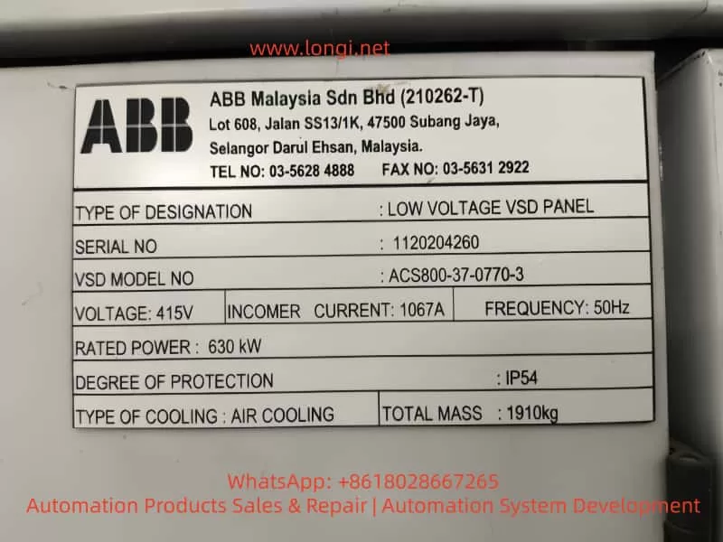
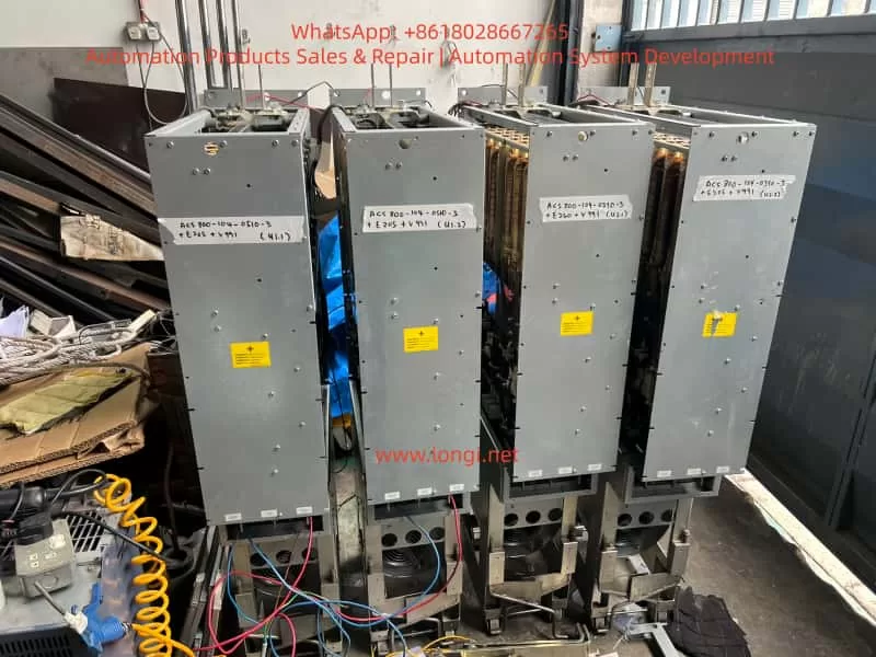
The ABB ACS800 drive series is widely used in metallurgy, mining, chemical plants, marine propulsion, and heavy industrial machinery. Known for its modular architecture and strong control capabilities, the ACS800-11 multidrive system combines line converter units (LCUs) with inverter units (INUs) through a common DC bus to deliver highly efficient variable speed drive and regenerative power control.
During field operation, however, maintenance teams often encounter the FF51 fault code (LINE CONV). This particular code indicates a malfunction on the line-side converter, which is critical because it manages the AC-to-DC conversion and grid interface. Unlike straightforward motor-side faults, FF51 requires engineers to investigate the health and operation of the line converter unit itself.
This article provides a comprehensive analysis of FF51:
Theoretical background of the ACS800 multidrive system,
Fault triggering mechanism,
Common causes and failure modes,
Interpretation of wiring diagrams and key inspection points,
Step-by-step troubleshooting workflow,
Case studies from industrial practice,
Preventive measures and maintenance guidelines.
The goal is to present a systematic methodology for resolving FF51 faults, minimizing downtime, and ensuring reliable operation in mission-critical applications.
2. Overview of the ACS800-11 Multidrive System
2.1 Major Components
An ACS800-11 multidrive typically consists of:
Line Converter Unit (LCU) – Converts incoming AC supply into a stable DC link, often using active front-end IGBT rectifiers for reduced harmonics and energy regeneration.
DC Link Bus – A shared bus that transfers energy between the LCU and multiple inverter units.
Inverter Units (INUs) – Convert DC back into AC with variable voltage and frequency to control motor speed and torque.
Control and Communication Modules – Including the Rectifier Control Unit (RMCU), Drive Control Panel (CDP), and fiber optic links for communication and monitoring.
2.2 Operating Principle
Rectification: The LCU rectifies grid power into DC, while maintaining power factor control and reducing harmonics.
Inversion: INUs convert DC into variable AC for motor operation.
Regeneration: During braking or load lowering, excess energy is returned to the grid via the LCU.
2.3 Why FF51 is Critical
The FF51 fault (LINE CONV) does not point to a single failed component. Instead, it acts as a system-level alert that something is wrong in the LCU. Engineers must further interrogate the LCU to identify the specific underlying fault, such as overvoltage, undervoltage, or hardware failure.
3. Definition and Triggering of FF51
3.1 Official Description
Code: FF51
Name: LINE CONV
Scope: ACS800-11 multidrive only
Meaning: A fault has been detected in the line-side converter. The system disables power transfer and may switch to motor-side supply if configured, while prompting the user to check the LCU.
3.2 Triggering Mechanism
FF51 can be triggered under three main conditions:
Supply anomalies – Grid imbalance, phase loss, voltage sags, or spikes.
Loose terminals or corroded connections leading to signal errors.
5. Diagram Interpretation and Key Checkpoints
The provided wiring diagrams of ACS800-11 highlight several critical inspection points:
Terminal Blocks (X20 / X25)
Distribution of control signals and auxiliary power.
Ensure stable +24 VDC and return paths.
RMCU to INU Fiber Communication
Verify optical link continuity and insertion quality.
Check signal strength at both ends.
Input Fuses F1/F2/F3
Confirm continuity using a multimeter.
Match replacement fuses to the specified ratings.
Rectifier Modules (U/V/W → DC+ / DC-)
Test for shorted or open devices using diode test mode.
Look for phase-specific failures.
Inductor and Busbar Connections
Verify tight mechanical connections.
Inspect inductance for open circuits or overheating.
6. Step-by-Step Troubleshooting Procedure
A systematic troubleshooting workflow for FF51:
Read Sub-Fault Codes
Access the CDP Line Converter menu.
Record detailed subcodes (e.g., undervoltage, IGBT fault, overvoltage).
Check Input Supply
Measure phase-to-phase voltages.
Verify fuses and contactors.
Test Power Components
Use a multimeter to test IGBT modules and diodes.
Inspect bus capacitors for ESR increase or leakage.
Verify Control and Communication
Check optical fiber links.
Measure +24 VDC and other auxiliary supplies.
Restart and Monitor
Power cycle the system after corrective actions.
Monitor whether FF51 reappears.
7. Case Studies from Industry
Case 1: Steel Rolling Mill
A rolling mill experienced recurring FF51 alarms. Analysis showed severe grid imbalance and phase drops. Installation of grid stabilizers and phase monitoring eliminated the issue.
Case 2: Mining Hoist
A mine hoist reported FF51. Investigation revealed a shorted IGBT in the line converter module. Replacement of the rectifier unit restored operation.
Case 3: Chemical Plant Pump
A chemical plant ACS800 system showed FF51 despite a stable grid. The issue was traced to a loose fiber optic link between the RMCU and inverter. Securing the connection solved the problem.
8. Preventive Measures and Maintenance
Power Quality Management
Use harmonic filters and reactive power compensation.
Avoid frequent voltage dips and disturbances.
Scheduled Component Testing
Inspect IGBT modules and DC bus capacitors annually.
Monitor ESR and thermal performance.
Signal and Connection Integrity
Tighten all terminals periodically.
Clean and secure optical connectors.
Data Logging and Predictive Maintenance
Maintain operational logs of fault history.
Use predictive diagnostics to identify early failure signs.
9. Conclusion
The FF51 fault (LINE CONV) in ABB ACS800-11 multidrive systems is a critical indicator of line converter malfunction. Causes typically fall into three categories: supply anomalies, hardware failures, or control/communication faults.
Effective resolution requires:
Detailed inspection of supply voltage and fuses,
Testing of rectifier modules and DC bus components,
Verification of RMCU communication and auxiliary supplies,
Stepwise elimination of potential issues based on wiring diagrams and fault history.
Preventive strategies such as power quality management, regular component checks, and proper maintenance of signal integrity are key to minimizing downtime.
With a structured troubleshooting workflow and proactive maintenance, industries can ensure long-term stability and reliability of their ACS800 multidrive systems.
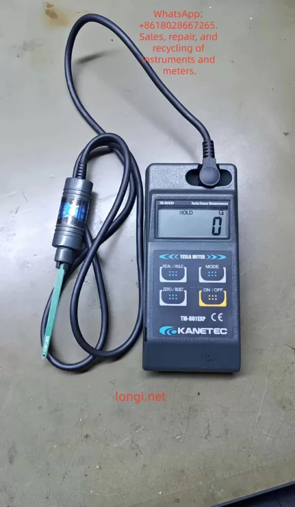
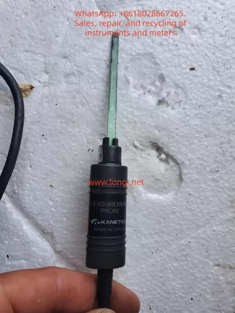
The KANETEC TM-801EXP Tesla/Gauss Meter is an electronic magnetic flux density measuring instrument based on the Hall Effect principle. The Hall Effect describes the phenomenon where, when current flows through a semiconductor, a magnetic field applied perpendicular to the current creates a voltage difference proportional to the magnetic flux density (Hall voltage).
The TM-801EXP uses this principle to convert magnetic flux density into an electrical signal, which is then amplified and displayed digitally on the LCD screen. It can measure both DC magnetic fields and AC magnetic fields (40–500 Hz, sine wave), while automatically identifying the polarity (N/S) of the magnetic field.
1.2 Key Features
Electronic design: compact and lightweight, weighing only about 250 g.
Wide measurement range: 0–3000 mT, suitable for weak to strong fields.
High resolution: minimum resolution of 0.01 mT (0.1 G).
Multiple modes: measures both DC and AC flux density; automatically displays N/S polarity.
Large LCD display: clear digital reading.
Data output: supports USB digital output and analog output for PC connection and data logging.
Energy saving: auto power-off in about 15 minutes to conserve battery.
No recalibration required: probe replacement does not require additional calibration.
1.3 Typical Applications
Measuring the flux density of electric motors, generators, and transformers.
Testing permanent magnets to check performance or demagnetization.
Measuring residual magnetism in processed parts, steel materials, or bearings.
Research on magnetic materials in laboratories.
Detecting the condition of stainless steel through magnetic response.
Evaluating the effectiveness of magnetic shielding materials.
2. Operation Instructions
2.1 Parts and Controls
ON/OFF: power switch; press and hold for about 2 seconds to turn on.
AC/DC switch: toggles between AC and DC field measurement.
REAL/HOLD: switches between real-time display and peak hold mode.
ZERO/RESET: forces reset to eliminate residual magnetism in the probe.
LCD display: shows magnetic field value, unit (mT/G), polarity (N/S), and mode.
Output ports: USB digital output, analog output, and external DC power input.
2.2 Measurement Procedure
Insert four AA 1.5V batteries or connect to an external DC 6V power supply.
Press and hold ON/OFF for 2 seconds to start; unit defaults to mT.
Gently place the probe onto the surface of the object under test—do not press forcefully to avoid probe damage.
Select DC or AC mode depending on the application:
DC mode: measures DC flux density and automatically shows N/S polarity.
AC mode: measures AC flux density in the 40–500 Hz sine wave range.
Press REAL/HOLD to switch between continuous real-time reading and peak hold mode.
After measurement, press ON/OFF to turn off, or the instrument will power off automatically after about 15 minutes.
2.3 Precautions
The probe is delicate—handle with care, and never apply excessive force.
Always return the probe to its protective case after use.
When the low battery icon appears on the LCD, replace all batteries.
Not suitable for electromagnetic wave measurement; only for static or low-frequency fields.
3. Calibration and Maintenance
3.1 Calibration Methods
Automatic zeroing: press ZERO/RESET to quickly eliminate zero drift.
Standard calibration blocks: for high accuracy, use KANETEC TM-SMF standard magnetic field blocks to compare values.
Probe replacement: probes are pre-calibrated by the manufacturer; replacement does not require additional calibration.
3.2 Routine Maintenance
Clean the unit regularly to prevent dust buildup around the connectors.
Remove batteries during long-term storage to prevent leakage.
Operate within the recommended environment: 0–40°C, 35–85% RH.
Always use the carrying case during transport to protect the probe.
4. Common Faults and Troubleshooting
4.1 Power Failure
Cause: Batteries depleted or poor battery contact. Solution: Replace with fresh batteries and check polarity.
4.2 Unstable Reading
Cause: Probe not zeroed, or strong electromagnetic interference nearby. Solution: Press ZERO/RESET to reset, or move away from interference sources.
4.3 Large Measurement Error
Cause: Probe damage or aging. Solution: Replace probe or recalibrate with standard blocks.
4.4 Polarity Not Detected
Cause: Magnetic field too weak or incorrect probe placement. Solution: Ensure close probe contact; if field is too weak, use high-sensitivity DC×10 mode.
4.5 No Output from USB Port
Cause: Driver not installed or cable defective. Solution: Install the official software/driver or replace USB cable.
5. Technical Specifications
Item
Specification
Model
TM-801EXP
Measurement Range
0–3000.0 mT
Resolution
0.01 mT (DC×10), 0.1 mT (AC/DC×1)
Modes
DC / AC (40–500 Hz)
Accuracy
±(3–5% of reading + digit error)
Unit
mT / G selectable
Polarity
N / S automatic detection
Functions
Zero reset, peak hold, auto power-off
Output
USB digital, analog output
Power Supply
1.5V AA ×4 or DC 6V external
Operating Environment
0–40°C, 35–85% RH
Dimensions
140(H) × 64(W) × 30(T) mm
Weight
Approx. 250 g (with battery and probe)
Standard Accessories
Probe, protective case, batteries, manual
Optional Accessories
TM-601DTC data cable, TM-SMF standard magnetic blocks
6. Conclusion
The KANETEC TM-801EXP Tesla/Gauss Meter is a lightweight, precise, and multifunctional magnetic field measurement tool. Using Hall Effect technology, it provides accurate DC and AC flux density readings, identifies magnetic polarity, and supports data logging through PC connections.
Its wide range of applications includes industrial inspection, magnetic material research, residual magnetism detection, and shielding evaluation. By following the recommended operating procedures, performing routine calibration and maintenance, and applying proper troubleshooting measures, users can ensure reliable performance and extend the service life of the instrument.
The TM-801EXP is thus a professional-grade tool combining portability, accuracy, and versatility, making it indispensable in both laboratory and industrial environments.
Polarimetry is an important analytical technique widely applied in pharmaceuticals, food, chemistry, sugar production, and research laboratories. Substances that can rotate the plane of polarized light are called optically active. By measuring this rotation, information such as concentration, purity, or specific rotation of the sample can be obtained.
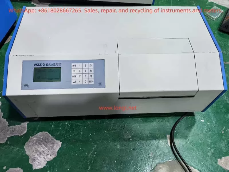
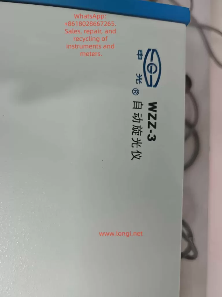
The WZZ-3 Automatic Polarimeter, manufactured by Shanghai Shenguang Instrument Co., Ltd., is a modern optical instrument that adopts the photoelectric automatic balance principle. Compared with manual polarimeters, it eliminates human reading errors, improves accuracy, and allows direct digital display of results. The instrument is equipped with multiple measurement modes, temperature control functions, and digital data interfaces, making it suitable for high-precision laboratory analysis.
This guide aims to provide a comprehensive reference for users by covering:
Principle and features of the WZZ-3 polarimeter
Temperature control methods
Calibration and adjustment procedures
Operation and routine maintenance
Common faults and troubleshooting methods
I. Principle and Main Features
1.1 Working Principle
The WZZ-3 polarimeter works based on the photoelectric automatic balance method. The measurement process can be summarized in the following steps:
Light Source
The WZZ-3 typically uses a high-stability LED combined with an interference filter to provide a monochromatic beam close to the sodium D line (589.44 nm).
Some older models use a sodium lamp.
Polarization System
The monochromatic light passes through a polarizer, producing linearly polarized light.
When the polarized light passes through an optically active substance (such as sugar solution, amino acid, or pharmaceutical compound), its polarization plane is rotated by a certain angle.
Analyzer and Detection
At the analyzer end, a photoelectric detector receives the rotated polarized light.
The change in light intensity is converted into an electrical signal.
Automatic Balance
The microprocessor adjusts the analyzer position automatically until light intensity reaches balance.
The rotation angle is calculated and displayed digitally as optical rotation, specific rotation, concentration, or sugar content.
1.2 Main Features
Multi-function Measurement: Supports direct measurement of optical rotation, specific rotation, concentration, and sugar content.
High Precision: Resolution up to 0.001°; repeatability ≤ 0.002°.
Automatic Operation: Automatically performs multiple measurements and calculates average values.
Temperature Control: Built-in temperature control ensures stable measurement conditions.
Digital Display and Output: Large LCD screen for real-time display; RS-232/USB interface for data transfer.
User-friendly: Simplified operation, reduced manual intervention, and minimized reading errors.
II. Temperature Control System
Optical rotation is temperature-dependent. Even small temperature changes can lead to measurable variations. The WZZ-3 is equipped with temperature control functions to ensure reliable and repeatable measurements.
2.1 Temperature Control Components
Sample Compartment with Jacket: Allows connection to a circulating water bath for precise control.
Built-in Heating Unit: Some models include an electric heater and sensor for direct temperature regulation.
Temperature Sensor: Monitors real-time sample temperature and provides feedback to the control system.
2.2 Control Range and Accuracy
Control Range: 15 ℃ – 30 ℃
Accuracy: ±0.5 ℃
2.3 Usage Notes
Preheat the instrument until both the light source and the temperature control system stabilize.
Ensure stable water circulation when using an external water bath.
For high-precision tests, always use a thermostatic water bath together with temperature-controlled sample tubes.
After use, drain water lines promptly to prevent scale buildup.
III. Calibration and Adjustment
3.1 Zero Adjustment
Turn on the instrument and allow 15–20 minutes for preheating.
Insert an empty sample tube (or keep the cell empty).
Select the Optical Rotation Mode and press the zero key to set the reading to 0.000°.
3.2 Calibration with Standard Sample
Use the supplied quartz calibration plate or standard solution.
Place it in the sample compartment and measure.
Compare measured value with certified standard value:
If deviation ≤ ±0.01°, calibration is valid.
If deviation exceeds the tolerance, enter the calibration interface, input the standard value, and let the system adjust automatically.
3.3 Instrument Adjustment
Verify that the light source is stable and sufficient in intensity.
Ensure optical alignment so that the beam passes centrally.
Re-measure the standard sample repeatedly to confirm consistency.
IV. Operation and Routine Maintenance
4.1 Operating Steps
Sample Preparation
Ensure the solution is homogeneous, transparent, and free of air bubbles or suspended particles.
Power On and Preheating
Start the instrument and allow adequate preheating time for light and temperature stabilization.
Mode Selection
Choose among optical rotation, specific rotation, concentration, or sugar content according to experimental requirements.
Loading the Sample Tube
Fill the tube without air bubbles; seal the ends properly.
Measurement
Press the measurement key; the instrument automatically performs multiple readings and calculates the average.
Reading and Output
View results on the LCD; if necessary, export data through the interface to a computer or printer.
4.2 Routine Maintenance
Sample Compartment Cleaning: Clean regularly to prevent contamination.
Optical Components: Do not touch with bare hands; clean with ethanol and lint-free cloth if necessary.
Light Source: Inspect periodically; replace if intensity decreases significantly.
Environmental Requirements: Keep away from direct sunlight, vibration, and high humidity.
Long-term Storage: Switch off power, disconnect cables, and cover with a dust-proof cover.
V. Common Faults and Troubleshooting
5.1 Light Source Not Working
Possible Causes: Lamp/LED damaged, power supply fault, or loose connection.
Possible Causes: Sample turbidity, temperature fluctuation, insufficient preheating.
Solution: Use a filtered and homogeneous sample; extend preheating; apply thermostatic bath.
5.3 Large Measurement Deviation
Possible Causes: Not calibrated, expired standard sample, or improper zero adjustment.
Solution: Re-zero the instrument; calibrate with quartz plate; replace standards.
5.4 Communication Failure
Possible Causes: Interface damage, incorrect baud rate, faulty cable.
Solution: Verify port configuration; replace cable; check PC interface.
5.5 Temperature Control Failure
Possible Causes: Faulty temperature sensor, unstable water circulation.
Solution: Inspect circulation system; check sensor connection; replace if necessary.
VI. Conclusion
The WZZ-3 Automatic Polarimeter is a high-precision, multi-functional instrument widely used for analyzing optically active substances. Its strengths lie in:
Photoelectric automatic balance technology
Accurate temperature control
Multi-mode measurement capability
Digital display and data communication
To ensure reliable results, users should pay special attention to:
Calibration procedures (zero adjustment and standard sample calibration)
Temperature stability (always use thermostatic control for critical experiments)
Sample preparation (avoid bubbles and impurities)
Routine maintenance (cleaning, light source inspection, and storage conditions)
By following the outlined procedures and troubleshooting methods, users can maintain the instrument’s accuracy, extend its lifespan, and ensure consistent performance in laboratory applications.
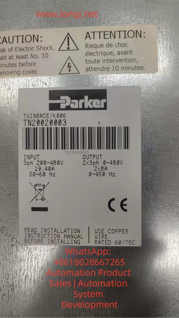
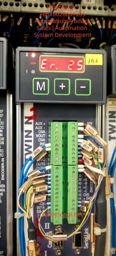
In modern industrial automation, servo drives play a crucial role. Acting as the bridge between motors and control systems, they must not only provide stable power and driving capability but also precisely process real-time signals from feedback devices. If the feedback system fails, the drive cannot initialize or operate correctly, leading to fault alarms and machine downtime. This article focuses on Error Code Er.25 in Parker TWIN-N series servo drives, analyzing its definition, root causes, troubleshooting methods, and preventive measures. It also presents real case studies and maintenance guidelines, offering engineers and technicians a comprehensive reference to handle this error effectively.
1. Overview of Parker TWIN-N Series Servo Drives
Parker Hannifin is a globally recognized provider of motion and control technologies. Its TWIN-N series servo drives are widely applied in packaging machines, textile equipment, electronic manufacturing, and other high-precision industrial automation fields.
Key features of the TWIN-N series include:
Dual-axis design: One drive can simultaneously control two brushless motors, saving space and cost.
Flexible parameter configuration: Different motor and feedback types can be adapted via parameter settings.
Advanced control functions: Provides position control, speed control, torque control, electronic cam, and other functions.
Among these functions, the correct initialization of feedback signals is critical. When the drive cannot establish a valid speed loop feedback, it triggers the Er.25 alarm.
2. Official Definition of Er.25
According to the Parker TWIN-N / SPD-N user manual:
This indicates that during startup, the drive fails to initialize the feedback required for the speed loop. Essentially, the drive cannot obtain valid speed feedback from the encoder or resolver, preventing the closed-loop control system from functioning.
3. Possible Causes of Er.25
Based on the manual and practical field experience, the following are the most likely causes of Er.25:
3.1 Incorrect feedback type configuration
The drive supports different feedback devices, and each requires correct parameter configuration:
Resolver mode for resolver feedback.
Incremental encoder mode with proper pulse number and supply voltage.
EnDat or Hiperface modes with specific communication protocols.
If the configuration does not match the actual feedback hardware, the initialization fails.
3.2 Wiring and connection issues
Feedback wiring typically includes power supply, signal lines, and shielding. Problems such as:
No voltage or reversed polarity on +5V / +8V power.
Broken, shorted, or swapped A/B/Z channels.
Incorrect Sin+/Sin− / Cos+/Cos− wiring.
Improper grounding of shield cables.
These can all cause the initialization error.
3.3 Faulty feedback device
Internal damage to the feedback device may lead to errors:
Open winding in resolver.
Malfunctioning photodiode in optical encoders.
EEPROM failure in EnDat/Hiperface devices.
3.4 Electromagnetic interference (EMI) and environment
Industrial sites often have strong EMI sources such as welding machines, large inverters, or solenoids. Poor shielding or excessive cable length may cause unstable signals at startup, leading to Er.25.
3.5 Drive hardware or firmware issues
If the feedback input board is defective or the firmware has bugs, the drive may also fail to initialize. Though less common, this should be considered after external causes are ruled out.
4. Step-by-Step Troubleshooting
A structured troubleshooting process ensures efficient diagnosis and resolution:
Step 1 – Verify feedback type configuration
Check drive parameter (e.g., Pr196) to confirm correct selection of Resolver, Incremental, or SinCos feedback.
Compare motor nameplate and encoder type with drive configuration.
Step 2 – Verify feedback power supply
Measure encoder supply voltage (+5V or +8V) with a multimeter.
Confirm stable supply, correct polarity, and no short circuits.
Step 3 – Inspect wiring and signals
Use an oscilloscope to check A/B/Z or Sin/Cos waveforms.
Ensure signal symmetry, integrity, and no significant noise.
Confirm secure wiring and proper shield grounding.
Step 4 – Perform encoder phasing (alignment)
Execute encoder phasing procedure if using incremental or SinCos encoders.
For EnDat/Hiperface, re-download EEPROM data if required.
Step 5 – Cross-test with a spare feedback device
Replace with a known good encoder/resolver to rule out sensor damage.
Step 6 – Check drive hardware
If external checks are normal, suspect damage to feedback interface or firmware issues. Contact the manufacturer or service center for repair.
5. Case Study
In a production line, a Parker TWIN8NSE K006 drive repeatedly showed Er.25 during startup. Investigation revealed:
The motor used an incremental encoder, but the drive remained configured in Resolver mode.
The encoder supply voltage was correct, but no pulses were detected at the signal terminals.
Solution:
Corrected the feedback type parameter to “Incremental Encoder.”
Re-wired the feedback cable and performed encoder phasing.
Restarted the drive, and the error disappeared.
This case highlights the importance of both parameter configuration and wiring inspection.
6. Preventive Measures
To minimize recurrence of Er.25, the following preventive practices are recommended:
6.1 Proper cabling
Use twisted, shielded cables for feedback signals.
Avoid routing feedback lines parallel to power cables.
Keep cable length within the specified range (typically 20–35 m).
6.2 Routine inspection
Check encoder waveforms every six months.
Clean connectors regularly to prevent dust or oil contamination.
6.3 Parameter management
After replacing or resetting the drive, always reconfigure feedback parameters.
Ensure firmware version supports the chosen feedback protocol.
6.4 Parameter backup
Save drive parameters in normal operation for quick restoration after faults.
6.5 EMI control
Keep drives away from strong EMI sources.
Use isolation transformers or EMI filters when necessary.
7. Conclusion
Error Code Er.25 in Parker TWIN-N series servo drives is a speed loop feedback initialization error. It is most commonly caused by incorrect feedback configuration, wiring problems, or faulty encoders. By applying a systematic troubleshooting approach—checking parameters, verifying wiring, confirming power, and testing feedback devices—engineers can quickly resolve the issue.
From a broader perspective, the feedback system acts as the “sensory organ” of the servo drive. Any malfunction, however minor, can disrupt the entire closed-loop system. Understanding the logic behind fault codes, combined with preventive maintenance practices, is essential for ensuring the long-term stability and reliability of servo drive systems.
The 752N Plus UV-Vis spectrophotometer displays a “low energy” warning (which may be accompanied by an NG9 or other low-energy prompt) at a wavelength of 220 nm (in the UV region), regardless of whether there is liquid in the cuvette or not. However, it functions normally at wavelengths above 300 nm (in the visible region). This is a typical fault related to the UV light source. Based on the instrument’s principles and common cases, the following provides a detailed explanation of the causes, diagnostic steps, and solutions. This issue does not affect visible light measurements, but if ignored for a long time, it may lead to data deviations in the UV region, affecting the accuracy of UV absorption analyses of nucleic acids and proteins.
Analysis of Fault Causes
The 752N Plus spectrophotometer employs a dual-light source design: a deuterium lamp (Deuterium lamp) is responsible for the UV region (approximately 190 – 400 nm, providing a continuous UV spectrum), and a tungsten-halogen lamp (Tungsten-halogen lamp) is responsible for the visible region (approximately 320 – 1100 nm). The instrument automatically switches to the deuterium lamp at wavelengths below 325 nm to ensure sufficient energy at short wavelengths.
Primary Cause: Deuterium Lamp Aging or Energy Degradation
The lifespan of a deuterium lamp is typically 800 – 1000 hours. After 2 – 3 years of use, the evaporation of the tungsten filament or a decrease in gas pressure can lead to insufficient output energy in the short-wavelength band (such as 220 nm), triggering a “low energy” alarm. Your symptoms highly match this scenario: there is no difference between an empty cuvette and a cuvette with liquid (ruling out cuvette problems), and only the UV region is abnormal (the tungsten lamp is normal). In similar cases, this type of fault accounts for more than 70% of UV-related issues.
Secondary Causes
Optical Path Contamination or Misalignment: Dust in the sample chamber, oxidation of mirrors, or clogging of slits can preferentially absorb UV light (since UV wavelengths are short and prone to scattering). However, since the problem persists with an empty cuvette, this possibility is relatively low.
Insufficient Warm-up or Switching Fault: The instrument requires a warm-up time of 30 – 60 minutes to stabilize the light sources. If the UV/visible switching motor or circuit board is damaged, it may also result in a false “low energy” warning.
Electrical Problems: An unstable power supply (<220V ± 10%) or a decrease in the sensitivity of the detector (photomultiplier tube, PMT) could be factors, but since the instrument functions normally above 300 nm, the probability is low.
Environmental Factors: High humidity (>85%) or low temperature (<15°C) can accelerate lamp degradation.
Eliminating the Impossible: The problem is not related to the liquid in the cuvette (as it occurs with an empty cuvette as well), and it is not a wavelength calibration deviation (since other wavelengths are normal).
Diagnostic Steps
Follow the steps below in order for self-inspection. Ensure that the power is turned off before operation to avoid static electricity. Required tools: white paper, compressed air, a lint-free cloth, and a multimeter (optional).
Basic Verification (5 – 10 minutes)
Confirm Warm-up: After turning on the instrument, wait for at least 30 minutes (ideally 60 minutes) and observe the light source chamber (through the ventilation grille on the back cover). The deuterium lamp should emit a weak purple light (UV light is invisible, but the lamp should have a uniform brightness). If there is no purple light or it flickers, it indicates a lamp fault.
Test Multiple Wavelengths: Set the wavelengths to 220 nm (UV), 250 nm (UV edge), 350 nm (visible switching point), and 500 nm (visible). If only the first two wavelengths show low energy, it confirms a deuterium lamp problem.
Check Error Codes: If the screen displays “NG9” or “ENERGY ERROR”, it directly indicates that the deuterium lamp energy is below the threshold (usually <50%).
Optical Path Inspection (10 – 15 minutes)
Open the sample chamber cover and shine a flashlight (white light) inside: Observe whether the light beam passes straight through the cuvette position without scattering or dark spots. If there are any issues, clean the sample chamber (use compressed air to blow away dust and a soft cloth to wipe the mirrors and slits).
Empty Cuvette Test: Insert a matching quartz cuvette (UV-specific, with a 1 cm optical path), close the cover tightly, press [0%T] to zero the instrument, and then press [100%T] to set the full scale. If the transmittance (%T) at 220 nm is still less than 90%, the cuvette can be ruled out as the cause.
Dark Environment Test: Turn off the lights in the room, set the wavelength to 530 nm (with a wide slit), and place a piece of white paper in the sample chamber to observe the light spot. If there is no light or the light is weak, check the integrity of the optical path.
Power Supply Test: Use a multimeter to check that the 220V power supply is stable and properly grounded.
Switching Test: Manually switch the mode (if the instrument supports it) or check the system settings (avoid accidentally selecting the “energy mode” in the menu).
If an oscilloscope is available, measure the output of the PMT (it should normally be >0.5V at 220 nm).
Diagnostic Step
Operation Points
Expected Results
Abnormal Indications
Warm-up Verification
Turn on the instrument and wait for 30 – 60 minutes, then observe the lamp
The deuterium lamp emits a uniform purple light
No light or flickering → Lamp fault
Multiple Wavelength Test
Set the wavelengths to 220/250/350/500 nm
Transmittance >95%T at both UV and visible wavelengths
Low transmittance only at UV wavelengths → Deuterium lamp problem
Optical Path Inspection
Shine a flashlight inside and clean the sample chamber
The light beam is clear
Scattering or dark spots → Contamination
Error Code Check
Read the screen
No error codes
NG9 → Insufficient energy
Solutions
Immediate Optimization (No Parts Required, Success Rate: 30%)
Extend the warm-up time to 1 hour and recalibrate the zero and full scale.
Clean the optical path: Use a lint-free cloth and isopropyl alcohol to wipe the cuvette and sample chamber, avoiding scratches.
Optimize the environment: Maintain a room temperature of 20 – 25°C and a humidity level of less than 70%.
Software Reset: Press and hold the reset button to restore the factory settings.
Steps: a. Turn off the power and open the back cover of the light source chamber (unscrew the screws). b. Pull out the old deuterium lamp (model: D2 lamp, 12V/20W, ensure the specifications match the 752N Plus manual). c. Install the new lamp: Align it with the axis and gently push it into place to secure it (do not touch the bulb). d. Turn on the instrument again, let it warm up for 60 minutes, and then run the self-test (menu > diagnostics). e. Calibration: Use a standard filter (e.g., a 220 nm holmium glass filter) to verify the wavelength and energy.
Cost and Precautions: The price of a deuterium lamp is approximately 300 – 500 yuan (available on Taobao or instrument stores). After replacement, record the usage hours (the instrument has a timer). If the switching motor is suspected to be faulty (web:0), check the drive board (seek professional repair).
Verification: After replacement, the transmittance (%T) of an empty cuvette at 220 nm should be greater than 98%, and the absorbance (A) should be 0.000 ± 0.002.
Other Repairs
Optical Path Adjustment: If there is misalignment, fine-tune the slit screws (requires tools from the manufacturer).
Circuit Board Replacement: If the PMT or CPU board is faulty, replace them (cost: 800 – 1500 yuan).
Annual Maintenance: Calibrate the wavelength and energy annually to extend the instrument’s lifespan.
Preventive Recommendations
Daily Maintenance: Conduct an empty cuvette test for both UV and visible regions every week. Replace the deuterium lamp when the usage exceeds 700 hours as a precaution.
Proper Operation: Always warm up the instrument before use; use quartz cuvettes (glass absorbs UV light); avoid exposing the instrument to direct sunlight and high humidity.
Backup: Keep 1 – 2 spare deuterium lamps on hand to minimize downtime.
This type of fault is common in instruments that have been in use for 1 – 2 years. In most cases, replacing the deuterium lamp can quickly resolve the issue. If the instrument also starts to show abnormalities above 300 nm, it may indicate overall aging, and upgrading to a newer model is recommended.
In modern industrial automation, Variable Frequency Drives (VFDs) have become the backbone of motor control systems. They regulate motor speed, improve energy efficiency, and provide precise process control. However, during operation or maintenance, technicians often encounter puzzling issues.
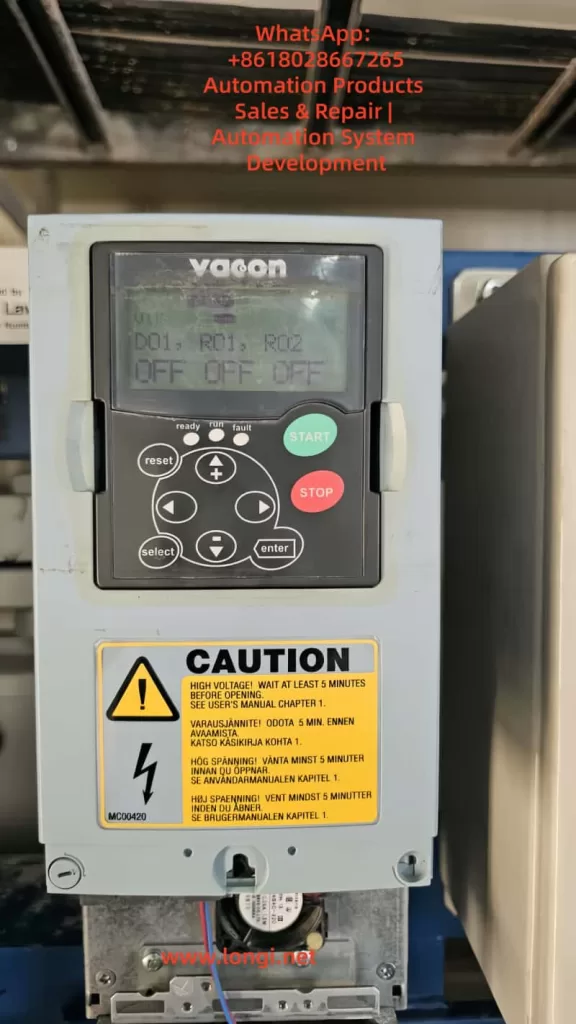
One common scenario is when a VACON drive powers up, the control panel works normally, but the READY indicator never turns on. At the same time, the monitoring menu shows DO1, RO1, and RO2 all in the OFF state.
At first glance, this situation may suggest a serious hardware fault. But in reality, the issue is usually tied to power supply conditions or run-enable signals, not an immediate hardware failure. This article will explain why the READY light fails to illuminate, what the OFF state of DO1/RO1/RO2 means, and how to systematically troubleshoot and resolve the problem.
I. Basic Structure and Operation of VACON Drives
1. Power Unit vs. Control Unit
Power Unit Converts incoming three-phase AC power into DC through rectification, then uses IGBT modules to invert the DC back into controlled AC for the motor. The READY light only turns on when the power unit has AC input and the DC bus voltage is established.
Control Unit Handles logic, parameter settings, monitoring, and communication. It can operate on external 24V control power even if the main power is disconnected. In this case, the keypad display works, but the READY light stays off.
2. Conditions for the READY Light
According to VACON manuals, the READY indicator lights up only when:
The main AC supply (L1/L2/L3) is present and the DC bus voltage reaches its threshold.
The drive completes its internal self-test without faults.
Required external enable/run signals are active.
If any of these conditions are not met, the READY light remains off.
II. Why DO1, RO1, and RO2 Show “OFF”
On the VACON keypad, the monitoring menu may display DO1, RO1, and RO2: OFF. This does not necessarily indicate a failure.
DO (Digital Outputs) and RO (Relay Outputs) are user-configured signals. Their ON/OFF status depends on the drive’s operating condition.
When the drive is not in READY mode or not running, all outputs typically remain OFF.
Thus, seeing all outputs OFF is normal when the drive has not yet transitioned into READY state. The real issue is the absence of the READY signal.
III. Common Causes for the READY Light Staying Off
1. Main Power Not Applied
The control board may be powered by 24V auxiliary supply, so the keypad works.
But if L1/L2/L3 main AC is not present, the DC bus is not charged, and the READY light will not turn on.
2. Missing Phase or Voltage Problems
Even if AC supply is connected, a missing phase or abnormal input voltage prevents the DC bus from charging correctly.
The drive will remain in a non-ready state.
3. Run-Enable Signal Not Closed
Many installations require an external Run Enable or Safe Torque Off (STO) input to be active before the drive transitions to READY.
If this input is open (for example, due to an emergency stop circuit or interlock), the READY light will not illuminate.
4. Active Faults Present
If the drive has detected a fault (overcurrent, overtemperature, STO error, internal error), READY will not turn on until the fault is cleared.
The keypad’s Active Faults menu (M4) should be checked.
5. Internal Hardware Failure
Less common, but damaged power modules, DC link capacitors, or power supply circuits can prevent READY.
These cases usually trigger fault codes, not just an OFF state.
IV. Step-by-Step Troubleshooting Procedure
To avoid incorrect assumptions or unnecessary replacements, follow a structured diagnostic process:
Step 1: Verify Main Power Supply
Measure voltage at L1/L2/L3. Confirm presence of three-phase AC.
Compare against the rated range (typically 380–500V for VACON NXS/NXP).
If no voltage is present, check upstream breakers or contactors.
Step 2: Check DC Bus Voltage
On the keypad, go to M1 → V1.8 (DC link voltage).
A healthy 400V-class system should read around 540V DC when energized.
If the value is near 0V, main power is not connected or rectifier is not operating.
Step 3: Inspect Run-Enable Inputs
Navigate to M1 → V1.13 / V1.14 (digital input status).
Verify that “Run Enable” or equivalent input is active.
If external interlocks are open, READY will not be established.
Step 4: Review Active Faults
Enter M4 Active Faults menu.
If faults are listed, diagnose and clear them before expecting READY.
Step 5: Reset and Reapply Power
Press RESET on the keypad.
If unresolved, disconnect main power, wait at least 5 minutes, then reapply.
Step 6: Escalate to Hardware Inspection
If power and signals are confirmed but READY is still off, inspect:
Power modules (IGBT stage)
DC bus capacitors
Internal auxiliary power supply circuits
These require professional service if damaged.
V. Real-World Case Studies
Case 1: Control Board Active, READY Light Off
At a manufacturing site, a VACON NXS drive displayed parameters on the keypad but showed no READY light. Investigation revealed that only the 24V auxiliary supply was applied, while the three-phase main input was disconnected. Once the breaker was closed, READY illuminated immediately.
Case 2: Missing Phase on Input
In a chemical plant, a VACON drive failed to reach READY state. Measurement showed one input fuse had blown, leaving the drive with only two phases. Replacing the fuse restored normal operation.
Case 3: Safety Circuit Open
On a packaging line, the drive’s READY light stayed off. Checking the digital inputs revealed that the Run Enable signal was inactive due to an emergency stop circuit being open. Resetting the E-stop allowed READY to activate.
VI. Preventive Maintenance and Best Practices
Ensure Stable Power Supply Regularly inspect incoming AC supply and fuses to prevent undervoltage or phase loss.
Maintain External Safety Circuits Clearly label Run Enable and STO wiring. Periodically test emergency stops and interlocks to ensure proper operation.
Monitor DC Bus Capacitors After several years of operation, bus capacitors may degrade, delaying or preventing READY. Routine inspection or preventive replacement is recommended.
Standardize Troubleshooting Procedures Develop a ready-made diagnostic checklist for maintenance staff. This avoids unnecessary downtime and reduces the risk of wrong component replacements.
Conclusion
When a VACON drive shows DO1, RO1, RO2 all OFF and the READY light remains off, it does not necessarily mean the drive is defective. In most cases, the cause lies in:
Main AC power not being applied,
Abnormal voltage conditions,
Run Enable signals not satisfied, or
Active faults that need clearance.
By following a structured diagnostic process—checking power input, DC bus voltage, external inputs, and faults—technicians can quickly pinpoint the root cause.
Understanding this typical failure mode saves time, reduces unnecessary repair costs, and ensures smoother operation of industrial systems.
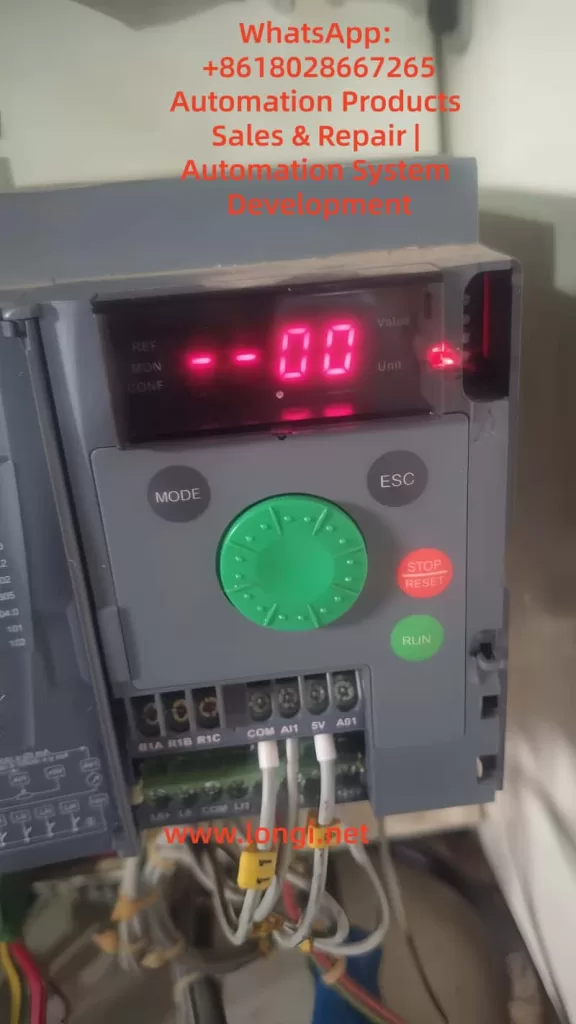
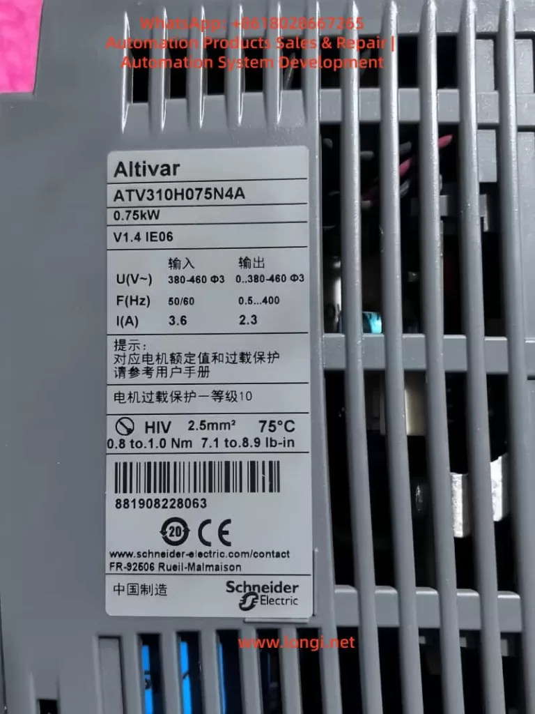
In industrial production, variable frequency drives (VFDs) are the core equipment for motor control and regulation. The Schneider ATV310 series is widely applied in fans, pumps, and conveyors due to its cost-effectiveness and stable performance. However, many users encounter the situation where the drive display shows “–00.” For operators unfamiliar with this model, this display may be mistaken as a fault or equipment failure. In fact, “–00” is not an error, but a normal status indication. This article explains the meaning of “–00,” analyzes the causes, discusses typical scenarios, provides troubleshooting guidance, and suggests solutions.
The True Meaning of “–00”
According to the Schneider ATV310 user manual, “–00” means the drive is in Ready status, meaning it has powered up and completed self-diagnosis but has not yet received a valid run command. The motor remains stopped. This is the factory default standby display. Once the user issues a run command and provides a valid speed reference, the display switches to show the actual output frequency or speed.
It is important to note that after freewheel stop or fast stop, the display will also return to “–00.” Therefore, “–00” can appear both at startup and after the motor has been stopped.
Common Causes
Several reasons may cause the ATV310 to stay on “–00”:
1. No Run Command Received
By default:
LI1 terminal is assigned as Forward run (2-wire control).
AI1 terminal is assigned as the speed reference (0–5 V).
If LI1 is not receiving a +24 V signal or AI1 is 0 V, the drive will remain at “–00.”
2. Local Control Not Enabled
Some users want to operate directly via the keypad and knob. However, the RUN/STOP keys and knob are disabled by default. To enable local control:
Set 401 (Reference channel 1) to 183 = Integrated keypad/knob.
Set 407 (Command channel 1) to Local.
After these settings, the drive can be run from the keypad and adjusted via the knob, and the display will change from “–00” to show real-time frequency.
3. Freewheel or Fast Stop Interference
If a digital input is assigned to “Freewheel stop” or “Fast stop” (parameters 502.1, 502.2), the drive will stop immediately when triggered and return to “–00.” Users should check whether these inputs are wrongly assigned or permanently active.
4. Control Method Mismatch
ATV310 supports both 2-wire and 3-wire control. If parameters 201 (Control type) and 202 (2-wire control type) do not match the wiring, run commands cannot be recognized. In addition, parameter 203 (Logic type) must match the wiring scheme: PNP wiring requires positive logic, while NPN wiring requires negative logic. Otherwise, the drive may ignore the input and remain at “–00.”
5. Drive Set to Bus Control
If the command channel is set to Modbus or remote mode but no communication command is received, the drive will stay at “–00,” waiting for instructions.
Troubleshooting and Solutions
The following systematic approach helps resolve the “–00” situation:
Step 1: Confirm Display Status
“–00”: Drive ready, motor stopped.
“502.1”: Freewheel stop active.
“–01”: Fast stop active. If always “–00,” the drive has not entered run mode.
Step 2: Check Command Source
Verify parameter 407 to see if the command source is Terminal or Local.
If Terminal: check that LI1 is receiving +24 V.
If Local: ensure 401 = 183 (HMI knob) and the knob is not at zero.
Step 3: Verify Speed Reference
If using AI1, ensure correct wiring (5V–AI1–COM) and output >0 V.
If using local knob, confirm it is enabled.
Step 4: Check Stop Functions
Verify that 502.1 and 502.2 are not assigned or permanently active.
Step 5: Confirm Logic Type
Parameter 203 must correspond to the wiring scheme: Positive logic for PNP, Negative logic for NPN.
Step 6: Restore Factory Defaults
If parameters are uncertain, restore defaults with 102 = 64, then reconfigure.
Practical Case Studies
Case 1: Missing Terminal Command
A technician found that a new ATV310 remained at “–00.” Investigation showed LI1 was not connected to +24 V. Once wired correctly, the drive ran normally.
Case 2: Knob Not Working
A user tried to run the drive via the knob but it stayed on “–00.” Parameters showed 401 still set to AI1 and 407 set to Terminal. After switching to Local, knob control worked.
Case 3: Stop Function Triggered
In one case, the drive stopped by itself after a short run and returned to “–00.” It was found that a faulty switch connected to the Freewheel stop input was randomly activating. Replacing the switch solved the issue.
Preventive Measures and Recommendations
Plan wiring before installation: Ensure parameters match wiring scheme (2-wire/3-wire, Local/Remote).
Test with Local mode first: Use keypad/knob to confirm basic functionality before enabling terminal control.
Avoid unnecessary stop inputs: Do not keep Freewheel/Fast stop terminals permanently active.
Routine checks: Inspect wiring and potentiometer regularly to avoid false “–00” conditions.
Parameter backup: Save critical parameter settings after commissioning for easy recovery.
Conclusion
The “–00” display on Schneider ATV310 drives is not an error but indicates the drive is ready while the motor is stopped. Common causes include missing run commands, zero speed reference, disabled local control, stop functions triggered, or logic mismatches. By following structured troubleshooting and aligning parameters with wiring, users can resolve this issue quickly. Correct configuration ensures reliable drive operation, prevents misinterpretation as faults, and enhances system stability and efficiency.
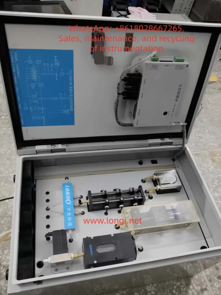
The LFS-2002(NH₃-N) is an ammonia nitrogen online water quality analyzer developed by Lihero Technology. It utilizes the colorimetric (chromogenic) principle to achieve online and automatic monitoring of ammonia nitrogen concentration in water through automatic sampling, reagent addition, mixing reaction, and colorimetric detection.
Scope of Application: Municipal water supply, sewage treatment plants, industrial wastewater discharge outlets, surface water, and groundwater monitoring.
Measurement Principle: After the sample water reacts with reagents, a colored complex is formed. Optical colorimetric detection is then performed at a specific wavelength, with the absorbance being directly proportional to the ammonia nitrogen concentration.
II. Startup Procedures
A. Pre-Startup Inspection
Confirm that the power supply is 220V AC, 50Hz, and reliably grounded.
Check that the reagent bottles (chromogenic agent, buffer, and distilled water) are full.
Ensure the waste liquid bottle is empty to prevent overflow.
Inspect the peristaltic pump tubing and colorimetric cell for air bubbles, blockages, or leaks.
B. Startup Operation
Turn on the instrument’s power switch.
The screen will display “System Initialization” → “Cleaning Detection Cell” (as shown in your photo).
The system will automatically perform the following steps: Cleaning → Reagent Tubing Filling → Colorimetric Cell Emptying → Preparation for Detection.
C. Entering Measurement Mode
After initialization is complete, the instrument enters the standby/measurement state.
According to the set monitoring cycle (e.g., every 15 minutes/1 hour), it automatically completes sampling, reagent addition, reaction, detection, and waste discharge.
III. Calibration Methods
Regular calibration of the ammonia nitrogen analyzer is necessary to ensure data accuracy.
A. Zero Calibration
Take distilled water or deionized water as the blank sample.
Select “Zero Calibration” through the operation interface.
After system operation, it will automatically clean → inject the blank water sample → measure absorbance → automatically adjust the zero point.
B. Span Calibration
Use a standard ammonia nitrogen solution (e.g., 1.0 mg/L or 5.0 mg/L).
Select “Span Calibration” and connect the standard solution to the sample tube.
After system operation, the instrument compares the measured result with the standard value and automatically corrects the slope.
C. Calibration Cycle
It is recommended to perform zero calibration once a week and span calibration once a month.
Recalibrate immediately after significant water quality changes or reagent replacement.
IV. Common Faults and Handling
Fault Phenomenon
Possible Causes
Handling Methods
Startup stuck at “System Initialization”
Air bubbles in the tubing, improperly installed peristaltic pump tubing
Check the pump tubing, remove air bubbles, and reinstall