Posted on

What’s the matter with the FF8E warning appearing on the ABB ACS800 series frequency converter, and how can it be resolved?

Introduction

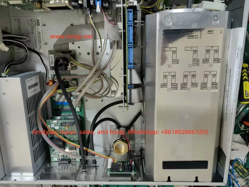
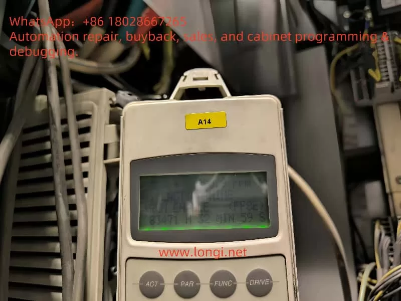
The ABB ACS800 series frequency converter is a robust solution widely used in industrial applications, supporting a power range from 0.75 to 7500 horsepower. However, one common issue users may encounter is the FF8E warning, which signals that the drive has not received the “Run Enable” signal required for operation. This article provides a detailed exploration of the FF8E warning, its causes, diagnostic steps, and solutions, drawing from official documentation and practical insights to guide users effectively.

FF8E

Understanding the FF8E Warning

The FF8E warning, classified as a “Run Enable” alert in the ACS800 series, indicates that the drive has not detected the necessary signal to start or continue motor operation. This signal serves as a safety and control mechanism, typically provided by an external device such as a PLC, control panel, or through fieldbus communication. When this signal is missing, the drive cannot operate, potentially disrupting production. The root causes of the FF8E warning generally fall into categories like parameter misconfiguration, wiring issues, or, less commonly, hardware faults.

Causes of the FF8E Warning

Based on ABB documentation and online discussions, the FF8E warning can be attributed to several potential causes:

  1. Parameter Configuration Issues
    • Incorrect Parameter 16.01 (RUN ENABLE) Setting: This parameter defines the source of the run enable signal. If misconfigured, the drive will fail to detect the signal.
      • Setting Options:
        • YES: Internal enable, no external signal required.
        • DI1-DI12: Signal provided via a specified digital input, which must be active.
        • COMM.CW: Signal provided via fieldbus communication, requiring active communication.
    • Signal Not Active: Even with the correct setting, if the digital input is not energized or the communication control word is not sent, the warning will persist.
    • Communication Failure: When set to COMM.CW, any interruption in fieldbus communication or failure to send the correct control word can trigger the FF8E warning.
  2. Wiring Issues
    • Poor 24VDC Contact: Unstable 24VDC power supply at pins 8 and 11 of the socket (e.g., due to loose contacts or corrosion) can disrupt the digital input signal.
    • Faulty Signal Source Wiring: Loose or damaged wiring for the run enable signal source can prevent the signal from reaching the drive.
  3. Hardware Issues
    • Mainboard or Digital Port Circuit Failure: Though rare, a damaged mainboard or digital port circuit can prevent the drive from detecting the signal. This is typically considered only after ruling out other causes.
    • Optional I/O Module Misconfiguration: If using extended I/O modules, improper configuration can lead to signal transmission failures.

Diagnostic and Resolution Steps

To effectively address the FF8E warning, users should follow these systematic steps:

  1. Verify Parameter 16.01 Settings
    • Using the drive’s control panel or a parameter configuration tool, confirm that parameter 16.01 aligns with the intended control method. For instance, if using a digital input, set it to the corresponding DI number; if using fieldbus, set it to COMM.CW.
    • Refer to the ACS800 Standard Control Program Firmware Manual (pages 42 and 252) for detailed parameter descriptions.
  2. Validate the Run Enable Signal
    • Digital Input: Check if the specified digital input (e.g., DI1-DI12) is active. This can be verified via the control panel or by measuring the voltage at the input terminal with a multimeter.
    • Communication Control: If using COMM.CW, ensure the fieldbus (e.g., Modbus or Profibus) connection is active and the control word (Main Control Word 03.01, bit 3) is correctly sent.
  3. Inspect Wiring
    • Focus on the 24VDC supply at pins 8 and 11 of the socket, ensuring secure contact with no looseness, corrosion, or contamination.
    • Check the wiring of the run enable signal source for continuity, ensuring there are no open circuits or shorts.
  4. Check Optional I/O Modules
    • If the drive uses extended I/O modules, verify the settings in parameter group 98 (OPTION MODULES) to ensure the module is correctly configured and active.
  5. Hardware Inspection
    • If the above steps fail, a hardware issue may be present. Open the drive and inspect the mainboard and digital port circuits for visible damage or poor connections.
    • Replacing the mainboard should be a last resort, pursued only after confirming a hardware fault, and ideally under guidance from ABB technical support.
  6. Consult Official Documentation and Support
    • Refer to the ACS800 Firmware Manual sections on “Start/Stop Control” and “Fault Tracing” for additional guidance.
    • For complex issues, contact ABB technical support for professional assistance.

Deep Dive into Parameter 16.01

Parameter 16.01 (RUN ENABLE) is central to resolving the FF8E warning. Below is a detailed breakdown:

Parameter NameDefault SettingFunction DescriptionSetting Options
16.01 RUN ENABLEYESSelects the source of the run enable signal, determining if the drive is allowed to operate– YES: Internal enable, no external signal needed
– DI1-DI12: Controlled via digital input
– COMM.CW: Controlled via fieldbus
  • Key Notes:
    • When using the Generic Drive protocol, set parameter 16.01 to “YES” to enable control via the fieldbus (Main Control Word 03.01, bit 3).
    • The run enable signal must be active for the drive to respond to start commands, such as an ID Run.

Hardware Concerns: Mainboard and Digital Port Circuits

While the FF8E warning is typically caused by configuration or wiring issues, hardware faults—such as a damaged mainboard or digital port circuit—can also prevent signal detection. These issues are less common and should only be considered after exhausting other troubleshooting steps. Replacing the mainboard is a costly and complex solution, requiring professional guidance to avoid further damage or warranty issues.

Preventive Maintenance

To minimize the occurrence of FF8E warnings, consider the following preventive measures:

  • Regular Wiring Checks: Ensure all control signal wiring is secure, with no looseness or corrosion.
  • Environmental Monitoring: Maintain a clean, dry, and well-ventilated environment for the drive, avoiding dust buildup or overheating.
  • Firmware Updates: Regularly check for and install firmware updates from ABB to address potential bugs.
  • Parameter Documentation: Keep a record of parameter settings and changes for easier troubleshooting in the future.
ACS800

Conclusion

The FF8E warning on the ABB ACS800 frequency converter indicates a missing run enable signal, often due to misconfigured parameter 16.01, poor 24VDC contact, or wiring issues. By systematically checking parameters, signals, wiring, and communication, most issues can be resolved. Hardware faults, such as mainboard or digital port circuit failures, are rare and should only be addressed after other possibilities are ruled out. Routine maintenance and proper configuration are key to ensuring the reliable operation of the ACS800 drive.

Posted on

ZK880-N Positive Control Inverter Three-Stage Speed Control Implementation Guide

In the field of industrial automation control, inverters, as the core equipment for motor speed regulation, are widely used in various scenarios requiring graded speed regulation, such as fans, pumps, and conveyor belts. This article will take the ZK880-N positive control inverter as an example, combined with official technical documentation and practical application scenarios, to elaborate in detail on how to achieve three-stage speed control through DI digital input terminals, providing systematic guidance from hardware wiring to parameter settings.

ZK880-N

I. Technical Principles of Three-Stage Speed Control

The essence of three-stage speed control is to preset the motor operating frequency into three different levels through the multi-stage speed instruction function of the inverter. Users can select the corresponding frequency band through external switch signals to realize the graded regulation of motor speed. The ZK880-N inverter uses digital input terminals (DI) as the trigger signal source, combined with function code parameter settings, to build a flexible and reliable multi-stage speed control system.

II. Hardware Wiring Implementation Steps

1. Terminal Function Definition

According to control requirements, the DI1-DI3 digital input terminals need to be configured as multi-stage speed control ports. Refer to the inverter terminal distribution diagram, with standard wiring terminals located in the control circuit interface area.

2. Wiring Specifications

  • Power Connection: Ensure that the main circuit power supply (R/S/T) and control circuit power supply (usually +24V) of the inverter are correctly connected.
  • DI Terminal Wiring:
    • DI1: As the first-stage speed trigger terminal, it is recommended to connect a normally open contact switch.
    • DI2: As the second-stage speed trigger terminal.
    • DI3: As the third-stage speed trigger terminal.
    • Common Terminal (COM): The signal common terminal for all DI terminals, which should be connected to the other end of the switch.

3. Wiring Precautions

  • The switch signal voltage range must comply with the DI terminal input specifications (5-30V DC).
  • It is recommended to use shielded twisted pair cables for signal transmission to avoid electromagnetic interference.
  • After wiring, use a multimeter to detect the insulation resistance between terminals to ensure there is no short circuit.

III. Detailed Explanation of Core Parameter Settings

The following function codes need to be configured through the operation panel or dedicated software:

1. DI Terminal Function Mapping

Function CodeParameter ItemSetting ValueFunction Description
F4-00DI1 Function Selection4Multi-stage Speed 1 (corresponding to the first-stage speed)
F4-01DI2 Function Selection5Multi-stage Speed 2 (corresponding to the second-stage speed)
F4-02DI3 Function Selection6Multi-stage Speed 3 (corresponding to the third-stage speed)

2. Multi-Stage Speed Frequency Settings

Function CodeParameter ItemSetting ValueTypical Application Scenarios
FC-00Multi-stage Speed 1 Frequency20HzLight load start/low-speed operation
FC-01Multi-stage Speed 2 Frequency35HzNormal working speed
FC-02Multi-stage Speed 3 Frequency50HzHigh-speed discharge/emergency acceleration

3. Operating Parameter Configuration

Function CodeParameter ItemRecommended ValueFunction Description
F6-00Acceleration Time 18.0sTransition time from first-stage to second-stage speed
F6-01Deceleration Time 15.0sTransition time from second-stage to first-stage speed
F6-02Acceleration Time 212.0sTransition time from second-stage to third-stage speed
F6-03Deceleration Time 28.0sTransition time from third-stage to second-stage speed
FC-16Operation Instruction Selection1Terminal control mode
FC-17Fault Reset Selection1Allow DI terminals to perform fault reset

IV. Realization of Three-Stage Speed Control Logic

1. Single Terminal Single-Stage Speed Mode

  • Only DI1 is closed: The motor operates at the frequency set by FC-00 (20Hz).
  • Only DI2 is closed: The motor operates at the frequency set by FC-01 (35Hz).
  • Only DI3 is closed: The motor operates at the frequency set by FC-02 (50Hz).

2. Combined Control Mode (Advanced Application)

Through function codes FC-03 to FC-07, combined stage speeds can be set:

  • DI1+DI2 closed: Execute the frequency set by FC-03 (reserved for extended stage speed).
  • DI2+DI3 closed: Execute the frequency set by FC-04 (reserved for extended stage speed).
  • Special application scenarios: Realize automatic stage speed switching logic through PLC programming.
ZK880-N

V. Commissioning and Verification Process

1. No-Load Test Stage

  1. Disconnect the motor load and only retain the inverter and dummy load.
  2. Close the DI1-DI3 switches in turn to observe whether the output frequency is consistent with the set value.
  3. Use an oscilloscope to detect the output voltage waveform and confirm there is no distortion.

2. Load Commissioning Stage

  1. Gradually load to the rated load.
  2. Test the current impact during stage speed switching (should be less than 1.5 times the rated current).
  3. Verify whether the acceleration/deceleration time meets the process requirements.

3. Abnormal Handling Test

  1. Simulate DI terminal signal adhesion fault.
  2. Verify the effectiveness of the FC-17 fault reset function.
  3. Test the reliability of overload protection (OL) action.

VI. Typical Application Cases

In a certain water plant’s constant pressure water supply system, the three-stage speed control of the ZK880-N inverter is adopted:

  • First-stage speed (25Hz): Maintain the basic pressure of the pipe network during night low-peak periods.
  • Second-stage speed (40Hz): Meet normal water demand during daytime water supply.
  • Third-stage speed (50Hz): Quickly supplement the pipe network pressure during peak water consumption periods.

Through the automatic switching of stage speeds by pressure sensor signals, an energy-saving rate of 32% is achieved, and the pressure fluctuation range is controlled within ±0.02MPa.

VII. Maintenance and Optimization Suggestions

  1. Regularly check the reliability of DI terminal wiring, and recommend tightening every six months.
  2. Recheck the FC-00 to FC-02 parameter settings every quarter according to load characteristics.
  3. Upgrade to the latest firmware version (currently V2.13) to obtain an optimized stage speed switching algorithm.
  4. For impact loads, it is recommended to add an input reactor to improve power quality.

By following the above systematic implementation steps, users can efficiently achieve the three-stage speed control function of the ZK880-N inverter. In practical applications, it is necessary to combine specific process requirements and optimize parameters to achieve the best control effect. With the development of Industry 4.0, this inverter supports the Modbus-RTU communication protocol and can be integrated with the host computer system to achieve more intelligent stage speed scheduling management.

Posted on

Guide to Resolving Fault 2281: Current Measurement Calibration on ABB ACS580 Drives

Introduction

The ABB ACS580 is a robust and reliable Variable Frequency Drive (VFD) widely used in industrial applications for precise control of AC motors. However, like any complex electronic device, the ACS580 may encounter faults that require troubleshooting and maintenance. One common issue is “Fault 2281,” which is related to current measurement calibration. This document provides a detailed explanation of the causes of Fault 2281, the roles of parameters 99.13 and 99.14, and a step-by-step guide to resolving this fault, ensuring the drive returns to normal operation. This guide is designed to offer clear and practical solutions for technicians and engineers while ensuring operational safety and equipment efficiency.

Fault 2281

What is Fault 2281?

Fault 2281 indicates an issue with the current measurement calibration of the ACS580 drive. This fault is typically triggered by the following reasons:

  • Excessive Measurement Offset: The measurement offset of the output phase currents exceeds the allowable range.
  • Interphase Discrepancy: The current measurement difference between output phases U2 and W2 is too large.
  • Incorrect Calibration Completion: The initial setup or previous calibration process may not have been executed correctly.
  • Hardware Issues: There may be faults in the current sensors, connecting cables, or the drive’s internal circuitry.
  • Environmental Interference: External factors such as temperature and electromagnetic interference may affect calibration stability.
  • Firmware Issues: The drive’s firmware version may be incompatible with the calibration requirements.

Fault 2281 is usually displayed on the drive’s display as “Fault 2281” with an auxiliary code (e.g., “0000 0003”), indicating the specific problem. Failing to resolve this fault may lead to inaccurate motor control, overheating, or equipment damage, making timely resolution crucial.

Why is Current Measurement Calibration Important?

Current measurement is one of the core functions of a VFD, directly affecting the drive’s performance and safety. Accurate current measurement serves the following purposes:

  • Device Protection: By monitoring the current, the drive can detect overloads, short circuits, or other anomalies and take protective measures (such as tripping or decelerating).
  • Performance Optimization: Precise current control ensures accurate motor torque regulation, suitable for applications requiring smooth operation.
  • Energy Efficiency: Reduces energy waste by adjusting motor speed according to load demands.
  • Diagnostic Support: Provides reliable current data for fault diagnosis and predictive maintenance.

If current measurement is not correctly calibrated, it may result in:

  • Torque control errors affecting motor performance.
  • Incorrect tripping or failure to trip, increasing the risk of equipment damage.
  • Inefficient operation, wasting energy.
  • Unreliable diagnostic data, complicating fault troubleshooting.

Therefore, regular calibration of the current measurement system is key to ensuring the efficient and reliable operation of the ACS580 drive.

Roles of Parameters 99.13 and 99.14

In the ACS580 drive, parameters 99.13 and 99.14 belong to the “Motor Parameters” group (Group 99) and are used to configure and execute Identification Run (ID Run), including current measurement calibration.

Parameter 99.14: Identification Run Condition

Parameter 99.14 is used to select the type of identification run. According to the provided documentation, the possible values for parameter 99.14 include:

ValueDescriptionEnglish Translation
0No identification operationNo identification operation
1Standard identification operationStandard identification operation
2Simplified identification operationSimplified identification operation
3Static identification operationStatic identification operation
4ReservedReserved
5Current measurement calibrationCurrent measurement calibration
6Advanced identification operationAdvanced identification operation

Setting parameter 99.14 to 5 indicates that the drive will perform current measurement calibration to adjust the internal current measurement system for accuracy.

Parameter 99.13: Identification Run Request

Parameter 99.13 is used to initiate the identification run. According to the ABB ACS580 firmware manual, this parameter allows the user to request the drive to execute an identification run, the specific type of which is defined by parameter 99.14. After setting parameter 99.13, the drive will perform the corresponding operation based on the setting in 99.14, such as current measurement calibration.

Synergy Between the Two Parameters

  • 99.14 specifies the operation type (e.g., a value of 5 indicates current measurement calibration).
  • 99.13 triggers the identification run, initiating the calibration process.

By correctly setting these two parameters, users can recalibrate the current measurement system to resolve Fault 2281.

ACS580

Steps to Execute Current Measurement Calibration

Below are the detailed steps to resolve Fault 2281 by setting parameters 99.13 and 99.14 to execute current measurement calibration:

  1. Ensure Safety
    • Power Off: Disconnect the drive from the power source to ensure complete de-energization and avoid electrical hazards.
    • Isolate the Motor: Ensure the motor has stopped and is disconnected from the load to prevent accidental startup.
    • Check the Environment: Ensure the working environment is free from electromagnetic interference or extreme temperatures that could affect the calibration.
  2. Access the Parameter Menu
    • Control Panel: On the ACS580 drive’s control panel, press the “Menu” or “Parameters” button to enter the parameter setup mode.
    • PC Tool: Use the ABB Drive Composer software to connect to the drive via the appropriate communication port and open the parameter setup interface.
  3. Navigate to the Motor Parameters Group
    • On the control panel, use the navigation buttons to scroll to “Motor Parameters” or Group 99.
    • In Drive Composer, browse the parameter list to find Group 99 (Motor Data).
  4. Set Parameter 99.14
    • Locate parameter 99.14 (Identification Run Condition).
    • Set its value to 5 (Current Measurement Calibration). Depending on the interface, this may involve selecting from a dropdown list or manually entering “5”.
  5. Initiate the Identification Run
    • Locate parameter 99.13 (Identification Run Request).
    • Set this parameter to initiate the identification run. Typically, this involves selecting “Start ID Run” or entering a specific value (refer to the manual for specific operations).
  6. Monitor the Calibration Process
    • The drive will perform current measurement calibration, which may last from a few seconds to a minute, depending on the drive and motor configuration.
    • Observe the control panel display for progress information or error messages.
  7. Verify the Calibration Results
    • After calibration is complete, check the drive’s display to confirm whether Fault 2281 has been cleared.
    • Use an external current measurement device (such as a current clamp) to verify that the current values displayed by the drive match the actual values.
  8. Save the Parameters
    • Save the changed parameter settings to ensure they are retained after a power outage.
    • On the control panel, this is usually done by selecting “Save” or “Confirm”; in Drive Composer, choose “Save Parameters”.

Troubleshooting Tips

If Fault 2281 persists after calibration, try the following methods:

  • Check Hardware Connections: Ensure the current sensors, motor cables, and terminal blocks are secure and free from loose connections or damage.
  • Check Hardware Integrity: Inspect the drive’s interior for physical damage or current sensor failures.
  • Verify Firmware Version: Ensure the drive’s firmware is up to date. The document mentions that versions below 99.7.3 may require calibration support from ABB Drives.
  • Refer to the Manual: Consult the ACS580 user manual’s troubleshooting section for specific meanings of auxiliary codes (such as 0000 0003).
  • Contact Technical Support: If the issue persists, contact technical support, providing the fault code, auxiliary code, and steps already attempted.

Common Errors and How to Avoid Them

When performing calibration, avoid the following common errors:

  • Not Powering Off: Ensure the drive is powered off before adjusting parameters to prevent unexpected behavior or safety risks.
  • Incorrect Parameter Settings: Confirm that you are adjusting parameters 99.13 and 99.14 and that their values are correct (99.14 set to 5).
  • Skipping Verification: After calibration, check if the fault has been cleared and verify the accuracy of the current measurement.
  • Ignoring Hardware Issues: If calibration is ineffective, check for hardware issues such as loose connections or damaged sensors.

Conclusion

Current measurement calibration is a critical step in ensuring the efficient and reliable operation of the ABB ACS580 drive. Fault 2281 indicates that the current measurement system needs recalibration. By correctly using parameters 99.13 and 99.14 and following the steps provided in this document, you can effectively resolve this fault and restore the drive to normal operation. Regular maintenance and calibration checks help prevent similar issues, extend equipment life, and maintain production efficiency. For further assistance, refer to the official documentation or contact ABB technical support.

Appendix: Parameter 99.14 Value Table

ValueDescriptionEnglish Translation
0No identification operationNo identification operation
1Standard identification operationStandard identification operation
2Simplified identification operationSimplified identification operation
3Static identification operationStatic identification operation
4ReservedReserved
5Current measurement calibrationCurrent measurement calibration
6Advanced identification operationAdvanced identification operation
Posted on

Detailed Explanation of Shihlin SS2 Inverter E0 Fault: Causes, Solutions, and Preventive Measures

Introduction

Inverters are vital components in industrial automation, enabling precise control over motor speed and torque across various sectors, including manufacturing and energy. The Shihlin SS2 series inverter, manufactured by Shihlin Electric, is widely recognized for its reliability and performance. However, like any complex equipment, it may encounter faults during operation. One such issue is the E0 fault, which can be perplexing for users due to its specific triggering conditions. This article provides a comprehensive analysis of the E0 fault in the Shihlin SS2 inverter, detailing its meaning, causes, solutions, and preventive measures to assist users in restoring normal operation efficiently.

E0

1. Meaning of the E0 Fault

According to the Shihlin SS2 Series Inverter Manual (version V1.07), the E0 fault is triggered under specific conditions related to the inverter’s parameter settings and operation mode. Specifically, when parameter P.75 (stop function setting) is set to 1, and the inverter is operating in a mode other than PU (panel operation mode) or H2 (high-frequency mode), pressing the stop button (labeled as “(20) key” in the manual) for 1.0 second causes the inverter to stop. The display shows “E0,” and all functions are disabled or reset. This behavior acts as a protective mechanism to prevent unintended operation or potential damage under these conditions.

Interestingly, the manual also lists E0 in the fault code table under “00(H00)” as “no fault” (无异常), which may indicate a different context, such as a default or reset state in fault logging. This dual reference suggests that E0’s meaning depends on the operational context, but the primary focus here is its association with the stop function and parameter P.75.

2. Causes of the E0 Fault

To effectively resolve the E0 fault, understanding its causes is essential. Based on the manual and related information, the following are the primary reasons for the E0 fault:

  • Parameter P.75 Configuration: Parameter P.75 governs the inverter’s stop behavior. When set to 1, it enables a deceleration stop function. In non-PU or non-H2 modes, pressing the stop button for 1 second triggers the E0 fault, as the inverter interprets this as an invalid operation under the current settings.
  • Operation Mode Restrictions: The E0 fault is specific to non-PU and non-H2 modes. PU mode allows direct control via the inverter’s control panel, while H2 mode may relate to specific high-frequency applications. Operating in external control mode (e.g., via external signals) with P.75 set to 1 increases the likelihood of triggering E0.
  • External STE/STR Command Interference: External start/stop commands (STE/STR) can conflict with the inverter’s settings. The manual notes that when E0 occurs, these external commands are canceled, suggesting that signal interference may contribute to the fault.
  • Operator Error: Inadvertently pressing the stop button for more than 1 second in an incompatible mode can trigger the E0 fault. This is particularly common during initial setup, debugging, or when operators are unfamiliar with the inverter’s operation.

It’s worth noting that earlier versions of the Shihlin SS2 manual (e.g., V1.01) describe E0 as a communication error related to parity check issues. This discrepancy indicates that fault code definitions may have evolved across manual versions, with V1.07 providing the most relevant information for modern SS2 inverters.

3. Solutions for the E0 Fault

Resolving the E0 fault involves a systematic approach to eliminate its triggers and restore normal operation. The following steps, derived from the manual (version V1.07), are recommended:

  1. Cancel External STE/STR Commands:
    • Inspect the inverter for any external start/stop (STE/STR) signals that may be interfering with its operation.
    • Cancel these inputs to ensure no external commands conflict with the inverter’s settings. In program operation mode, manual signals typically do not require clearing, but verifying the absence of interference is critical.
  2. Reset the Inverter:
    • Locate the stop button (labeled “(20) key”) on the control panel.
    • Press and hold it for at least 1.0 second to clear the E0 fault and reset the inverter to an operational state. This is a direct method recommended in the manual.
  3. Check and Adjust Parameter P.75:
    • Access the inverter’s parameter setting menu to review the value of P.75.
    • If P.75 is set to 1 and this is not suitable for your application, change it to 0 (the factory default) or another appropriate value. Refer to section 5.33 of the manual for detailed guidance on adjusting P.75.
  4. Verify Operation Mode:
    • Ensure the inverter is operating in the correct mode (PU or H2, if required for your application).
    • Switch to the appropriate mode to prevent the fault from recurring.
  5. Perform a Parameter Reset:
    • If the above steps do not resolve the issue, use parameters P.996 or P.997 to reset the inverter. These parameters can clear fault records or restore factory settings, as outlined in sections 5.78 and 5.80 of the manual.
  6. Seek Professional Assistance:
    • Persistent faults may indicate hardware issues (e.g., faulty motherboard or wiring errors) or complex configuration problems.
    • Contact Shihlin Electric’s technical support team via their official website or arrange for the inverter to be inspected by the manufacturer.

The following table summarizes the causes and solutions for the E0 fault:

Possible CauseSolution
P.75 set to 1, non-PU/H2 mode operationAdjust P.75 to 0 or other values (manual section 5.33)
Stop button pressed for 1.0 secondPress stop button for 1.0 second to reset
External STE/STR command interferenceCancel external commands, check wiring
Hardware or configuration issuesReset using P.996/P.997 or contact manufacturer
SS2 inverter

4. Preventive Measures for E0 Fault

To minimize the occurrence of E0 faults and ensure reliable inverter operation, consider the following preventive measures:

  • Proper Parameter Configuration:
    • During installation and commissioning, thoroughly review the Shihlin SS2 Series Inverter Manual (version V1.07) to ensure parameters like P.75 are correctly set for your application.
    • Avoid modifying parameters without understanding their functions to prevent unintended faults.
  • Regular Maintenance:
    • Conduct periodic inspections of the inverter’s wiring, cooling system, and control panel to check for loose connections, dust buildup, or overheating.
    • Regular maintenance reduces the risk of faults caused by environmental or mechanical issues.
  • Operator Training:
    • Train all personnel operating the SS2 inverter on its proper use and fault-handling procedures.
    • Ensure the manual is readily available for quick reference during operation or troubleshooting.
  • Power Supply Stability:
    • Use voltage stabilizers or surge protectors to protect the inverter from power fluctuations, which can contribute to faults.
    • A stable power supply is essential for long-term reliability.
  • Fault Monitoring and Logging:
    • Maintain a record of all fault occurrences, including their conditions and resolutions.
    • Regularly monitor the inverter’s performance to identify and address potential issues early.

5. Conclusion

The E0 fault in the Shihlin SS2 inverter, while initially confusing, can be effectively managed by understanding its association with parameter P.75 and specific operation modes. By following the outlined steps—canceling external STE/STR commands, resetting the inverter, adjusting P.75, and verifying the operation mode—users can typically resolve the fault quickly. Additionally, adopting preventive measures such as proper parameter setup, regular maintenance, operator training, power protection, and fault monitoring can significantly reduce the likelihood of E0 faults. For persistent issues, contacting Shihlin Electric’s technical support or arranging professional inspection is advisable. By implementing these strategies, users can ensure the stable and efficient operation of their SS2 inverters, maximizing performance in industrial applications.

Key Citations

Posted on

Design and Application of Constant Pressure Water Supply Control System Based on Milan M5000 Inverter and YTZ-150 Potentiometric Pressure Sensor

1. System Overview

Constant pressure water supply technology is widely used in modern industrial and civil water systems for efficient and energy-saving operation. This project uses the Milan M5000 inverter as the control core, combined with the YTZ-150 potentiometric remote pressure gauge, to construct a closed-loop constant pressure control system. It enables automatic adjustment of a single water pump to ensure the outlet pressure remains stable within the set range.

The system features low cost, easy maintenance, and fast response, making it suitable for small water supply systems, factory cooling water circulation, boiler water replenishment, and more.


M5000 INVERTER

2. Main Hardware and Functional Modules

1. Inverter: Milan M5000 Series

  • Built-in PID controller
  • Supports multiple analog inputs (0-10V, 0-5V, 4-20mA)
  • Provides +10V power output terminal for sensor power supply

2. Pressure Sensor: YTZ-150 Potentiometric Remote Pressure Gauge

  • Resistive output with a range of approx. 3–400Ω
  • Rated working voltage ≤6V, but 10VDC tested in practice with stable long-term operation
  • Outputs a voltage signal (typically 0–5V) varying with pressure via a voltage divider principle

3. Control Objective

  • Adjust pump speed using the inverter to maintain constant pipe pressure
  • Increase frequency when pressure drops, and decrease when pressure exceeds the setpoint to save energy

3. Wiring and Jumper Settings

1. 3-Wire Sensor Wiring (Tested with 10V)

Sensor WireFunctionInverter Terminal
Red+10V supplyConnect to +10V
GreenGround (GND)Connect to GND
YellowSignal outputConnect to VC1 input

2. Analog Input Jumper JP8

  • Default: 1–2 connected, indicating 0–10V input
  • Keep the default setting in this project (no need to switch to 2–3)

YTZ-150 Potentiometric Pressure Sensor

4. PID Parameter Settings (Based on Field Use)

ParameterDescriptionValueNote
P7.00Enable closed-loop control1Enable PID control
P7.01Setpoint source0Digital input from panel
P7.02Feedback source0VC1 analog input (0–10V)
P7.05Target pressure value (%)30.0Corresponds to 0.3MPa if P7.24=1.000
P7.07Feedback gain1.00Linear scaling factor for feedback
P7.10PID control structure1Proportional + integral control
P7.11Proportional gain0.50Recommended initial value
P7.12Integral time constant10.0In seconds
P7.24Pressure sensor range (MPa)1.0001.000 MPa full-scale
P1.19Maximum voltage input5.00Matched to 0–5V signal range

5. Sleep Function Configuration

To enable energy saving when there is no pressure demand, the inverter can be configured to sleep:

ParameterDescriptionValueNote
P7.19Wake-up threshold0.001Minimum pressure to resume operation (MPa)
P7.20Sleep threshold1.000Enter sleep mode above this value (MPa)
P7.23Constant pressure mode1One-pump control mode

6. PID Tuning Guidelines

  1. After starting the system, observe pressure fluctuations:
    • If large oscillations, reduce P7.11 (proportional gain)
    • If sluggish response, reduce P7.12 (integral time)
  2. Aim to maintain output pressure within ±2% of the P7.05 set value
  3. Ensure return pipes have damping to prevent sudden pressure spikes

7. Key Considerations

  1. Keep JP8 jumper at default 1–2 for 0–10V input
  2. YTZ-150 sensor has been tested with 10V power supply and works stably
  3. Ensure proper grounding (PE terminal) to avoid PID interference from common-mode noise
  4. If feedback signal is noisy, add a filter capacitor (0.1–0.47μF) between VC1 and GND

8. Conclusion

With this design, the Milan M5000 inverter combined with the YTZ-150 pressure sensor delivers a cost-effective and reliable constant pressure control solution for water systems. The inverter’s built-in PID control simplifies implementation compared to external PLCs and offers strong performance with minimal tuning. As long as power supply, signal matching, and grounding are properly managed, the system achieves excellent closed-loop control stability.

Posted on

User Guide for ABB EL3020 Continuous Gas Analyzer

Key Takeaways

  • Powerful Functionality: The ABB EL3020 is a high-precision continuous gas analyzer supporting multiple modules (e.g., Uras26, Magnos206) for industrial gas monitoring.
  • Wide Applications: Primarily used in non-hazardous environments for measuring flammable gases, suitable for industrial process control and environmental monitoring.
  • Operational Caution: Must be operated by qualified personnel, adhering to strict safety and installation requirements to prevent leaks or equipment damage.
  • Maintenance and Troubleshooting: Regular calibration and seal integrity checks are critical; fault codes provide clear diagnostics for timely resolution.
  • User-Friendly Design: Features an intuitive display interface and multiple connectivity options, supporting remote configuration and data logging.

This guide, based on the ABB EL3020 user manual, aims to assist users in understanding its features, usage, precautions, and maintenance procedures.


ABB EL3020

Features and Capabilities

The ABB EL3020 is a continuous gas analyzer designed for industrial applications, capable of accurately measuring the concentration of individual components in gases or vapors. Part of the ABB EasyLine series, it combines advanced technology with user-friendly design, making it suitable for various industrial settings.

Key Features

  • Versatile Analyzer Modules: Supports Uras26 (infrared), Magnos206 (oxygen), Caldos27 (thermal conductivity), Limas23 (ultraviolet), and ZO23 (zirconia) modules, enabling measurement of gases like CO, CO₂, CH₄, and O₂.
  • Robust Design: Housed in a 19-inch rack-mounted enclosure with IP20 protection, weighing 7-15 kg, ideal for indoor industrial environments.
  • Flexible Connectivity: Supports 100-240 V AC power, digital I/O, analog outputs, Modbus, Profibus, and Ethernet interfaces for seamless system integration and remote operation.
  • Calibration Options: Offers automatic and manual calibration using nitrogen, air, or span gases, configurable via the device or software (e.g., ECT).
  • Intuitive Interface: Displays gas component names, measured values, and units in measurement mode; menu mode provides configuration and maintenance functions with password protection and a 5-minute timeout.
  • Data Communication: Connects to computers via Ethernet using TCT-light and ECT software for configuration, calibration, and data logging, supporting Modbus TCP/IP protocol.

Applications and Usage Precautions

Applications

The ABB EL3020 is designed for measuring flammable gases in non-hazardous environments, with applications including:

  • Industrial Process Control: Monitors gas concentrations in production processes to ensure stability.
  • Environmental Monitoring: Measures industrial emissions to comply with regulatory standards.
  • Energy Sector: Used in power plants for gas analysis to enhance efficiency and safety.
  • Chemical Industry: Monitors gas components in chemical reactions to ensure safety and quality.

The device is suitable for indoor environments below 2000 meters altitude, with flammable gas concentrations not exceeding 15 vol.% CH₄ or C1 equivalents. It is not suitable for ignitable gas/air or gas/oxygen mixtures or corrosive gases without proper preprocessing.

Usage Precautions

To ensure safety and performance, adhere to the following precautions:

  • Personnel Requirements: Only qualified personnel familiar with similar equipment should operate or maintain the device.
  • Safety Compliance: Follow national electrical and gas-handling safety regulations, ensure proper grounding, and avoid using damaged or transport-stressed equipment.
  • Installation Environment: Install in a stable, well-ventilated location away from extreme temperatures, dust, and vibrations. For flammable gas measurements, ensure adequate air circulation (minimum 3 cm clearance), and if installed in a closed cabinet, provide at least one air change per hour.
  • Gas Handling: Use stainless steel or PTFE gas lines, avoid opening combustion gas paths, and regularly check seal integrity to prevent leaks that could cause fires or explosions. Limit combustion gas flow (e.g., max 10 l/h H₂ or 25 l/h H₂/He mixture) and install a shut-off valve in the gas supply line.
  • Environmental Protection: Protect the device from mechanical damage or UV radiation, especially the display window.
  • Usage Restrictions: The oxygen sensor and integrated gas feed option must not be used for flammable gas measurements.

ABB EL3020

Detailed Usage Steps and Methods

Preparation

Before installing the EL3020, ensure:

  • Thorough review of the manual to understand application and safety requirements.
  • Preparation of necessary materials, such as gas lines, fittings, and power cables.
  • Verification that the installation site meets environmental requirements (stable, ventilated, no extreme temperatures).

Unpacking and Installation

  • Unpacking: Due to the device’s weight (7-15 kg), two people are recommended for unpacking.
  • Gas Connections: Use PTFE sealing tape to connect sample, process, and test gas lines, ensuring a tight seal.
  • Installation: Secure the 19-inch enclosure in a cabinet or rack using appropriate mounting rails.

Connections

  • Gas Lines: Connect sample, process, and test gas lines, ensuring cleanliness and secure sealing. Install a micro-porous filter and flowmeter for protection if needed.
  • Electrical Connections: Connect power (100-240 V AC), digital I/O, analog outputs, and communication interfaces (Modbus, Profibus, Ethernet) as per the manual’s wiring diagrams.

Startup

  1. Power On: Connect and turn on the power supply.
  2. Purging: Purge the sample gas path with an inert gas (e.g., nitrogen) for at least 20 seconds (100 l/h) or 1 hour (200 l/h) to clear residual gases.
  3. Warm-Up: Allow 0.5-2 hours for warm-up, depending on the analyzer module.
  4. Introduce Sample Gas: After warm-up, introduce the sample gas.
  5. Configuration and Calibration: Verify configuration settings and perform calibration if necessary, using test gases (e.g., nitrogen) to adjust zero and span points.

Operation

  • Measurement Mode: The display shows gas component names, measured values, and units for routine monitoring.
  • Menu Mode: Access configuration, calibration, or maintenance functions via the menu, requiring a password. The system auto-exits after 5 minutes of inactivity.
  • Calibration Methods: Perform automatic calibration (using preset test gases) or manual calibration (via menu or ECT software to adjust setpoints).
  • Data Logging: Use TCT-light or ECT software via Ethernet for data recording, compliant with QAL3 requirements.
  • Remote Monitoring: Integrate with monitoring systems via Modbus TCP/IP protocol.

Routine Maintenance and Fault Code Meanings

Routine Maintenance

To ensure long-term performance, conduct regular maintenance:

  • Seal Integrity Checks: Use pressure tests or leak detectors to regularly verify the integrity of sample and combustion gas paths, ensuring a leak rate < 1×10⁻⁴ hPa l/s for combustion gas and < 2×10⁻⁴ hPa l/s for sample gas.
  • Calibration: Perform automatic or manual calibration as needed, using specific test gases (e.g., nitrogen) to adjust setpoints and ensure measurement accuracy.
  • Visual Inspection: Regularly check for wear, damage, or contamination, particularly in gas lines, fittings, and the display.
  • Software Updates: Periodically update ECT and other software to ensure compatibility and functionality.

Fault Codes

The EL3020 provides status messages (codes 110 to 803), categorized as follows:

  • A: Failure
  • W: Maintenance Request
  • F: Maintenance Mode
  • S: Overall Status

Common fault codes and their handling methods are listed below:

CodeCategoryMeaningHandling Method
110A S aInstrument is bootingNo action required, informational
122A S aIO module defectiveReplace IO module
250A S aAnalyzer not foundCheck connectors and cables
301A S aMeasured value exceeds A/D converter rangeCheck sample gas concentration and connectors, contact service if needed
322A S aFlame is outCheck gas supply and heater plug (for flame-based modules)
412F S aIgnition failedManually restart via menu, check process gases

Maintenance Procedures

  • Identify Fault: Access fault codes via the menu.
  • Troubleshooting: Follow the manual’s instructions for each fault code. For example:
    • Code 322 (Flame Out): Check combustion gas supply and heater plug.
    • Code 250 (Analyzer Not Found): Inspect cables and connectors.
  • Contact Service: If the issue persists, contact ABB Service; avoid attempting repairs beyond your qualifications.

Conclusion

The ABB EL3020 Continuous Gas Analyzer is a robust and versatile tool for industrial gas monitoring, offering high precision and flexibility across various applications. By following the usage steps, precautions, and maintenance procedures outlined in this guide, users can ensure safe operation and sustained performance. Regular calibration, seal integrity checks, and prompt resolution of fault codes are essential for maintaining measurement accuracy and safety.

Posted on

Practical Guide: Connecting 9 Schneider VFDs Directly to HMI via Ethernet Network


1. Project Overview

This project aims to build a control network without using a PLC by directly connecting 9 Schneider Altivar-310 series variable frequency drives (VFDs) to a human-machine interface (HMI) through the Modbus TCP protocol. The HMI serves as the sole Modbus master, and all VFDs function as slave devices, enabling direct command transmission, status monitoring, and parameter interaction.

This architecture is especially suitable for small to medium automation systems, reducing hardware costs, simplifying the control structure, and improving debugging efficiency.


ATV310

2. Hardware Checklist

ItemFunctionNotes
Altivar 310 + VW3A3616 module × 9Ethernet interface for each VFDInstall securely into the communication option slot
Industrial Ethernet switch (≥10 ports, 100 Mbps is fine)Star topology backboneDIN-rail mount, industrial-grade recommended
Shielded CAT5E/6 Ethernet cablesNoise-resistant communicationKeep under 100 meters; ground shield at one end
HMI panel supporting Modbus TCPActs as the master deviceWeintek, Schneider Magelis, and similar brands recommended
24V DC power supply (if required by HMI)Auxiliary power sourceAll devices should share the same PE grounding system

3. Recommended IP and Modbus Address Allocation

VFD No.Static IPSubnet MaskModbus Slave ID
1192.168.0.11255.255.255.01
2192.168.0.12255.255.255.02
9192.168.0.19255.255.255.09

Tip: Assign the HMI an address like 192.168.0.10. If used in an isolated system, the gateway can be set to 0.0.0.0.


4. Configuring IP Address for Each VFD Using SoMove

  1. Connect the PC to the VFD via Ethernet cable and set the PC’s IP address to the same subnet (e.g., 192.168.0.100).
  2. Launch the SoMove software, select Modbus TCP as the communication type, and enter the target VFD’s IP address (default or temporary), with Modbus slave address set to 1.
  3. In the Communication → Ethernet menu:
    • Set IP Mode to Manual
    • Enter a unique static IP for each VFD (e.g., 192.168.0.15)
    • Set subnet mask to 255.255.255.0
    • Set gateway to 0.0.0.0 or as required by your network
    • Set protocol to Modbus TCP (value = 0)
    • Set Modbus slave address from 1 to 9
  4. Save the parameters and reboot the VFD to apply the new IP.
  5. Repeat this process for all 9 drives, assigning unique IPs and Modbus IDs.

ATV310 modbus TCP

5. HMI Modbus Register Mapping Example

FunctionRegister Address (Offset)Data TypeScaling
Command word (Run/Stop, Direction)016-bitBit-level
Frequency setpoint (Hz)116-bit0.1 Hz per bit
Output frequency feedback10216-bit0.1 Hz per bit
Drive status word12816-bitBit-level
Fault code12916-bitInteger

Note: The ATV310’s Modbus register map starts at 40001. Some HMI brands use “offset 0”, so register 1 corresponds to 40001.


6. Network Topology and Installation Practices

  1. Star Topology: Connect all 9 VFDs and the HMI to a central switch.
  2. EMC Wiring Practices:
    • Separate power and Ethernet cable routing to minimize interference
    • Bond all VFDs and the switch ground terminals to the control cabinet’s PE bar
  3. Labeling and Documentation:
    • Clearly label each Ethernet cable with corresponding VFD number and IP
    • Place a printed network topology diagram inside the control cabinet

7. Commissioning Procedure

  1. Ping Test: Use a PC to ping each VFD’s IP address to verify communication.
  2. HMI Communication Test:
    • Create a template screen for one VFD
    • Copy it for other VFDs, changing only the IP and Modbus ID
    • Test frequency control, start/stop, and feedback display for each unit
  3. Stress Test: Run rapid start/stop cycles and observe response consistency and screen refresh speed (<200 ms is ideal).
  4. Project Backup: Save each VFD’s .stm file from SoMove and the full HMI project into a version-controlled system.

8. Performance & Limitations

AspectDetails
Max refresh speedReading 10 registers per drive takes ~20–40 ms; 9 drives ≈ 200–400 ms total
Real-time behaviorSuitable for monitoring and basic control; not ideal for high-speed interlocks (<20 ms)
RedundancyA single switch failure disconnects all; consider dual-ring switches for critical uptime
SecurityUse VLANs or restrict switch ports to specific MACs to prevent unauthorized connections

9. Maintenance and Optimization Tips

  • Always backup SoMove configuration files after parameter changes
  • Stick Modbus slave ID labels onto each VFD’s front panel
  • Lock HMI screens with password protection to prevent accidental changes
  • Annually inspect Ethernet switch ports; replace the unit if CRC errors or dust buildup is found

10. Conclusion

By installing VW3A3616 modules and configuring individual IP addresses and Modbus IDs for each ATV310, a clean star-topology network can be built for direct HMI communication. This setup simplifies wiring, eliminates the need for a PLC, and significantly reduces costs. It is particularly suitable for small to medium-sized automation projects that require easy maintenance and flexible deployment.

Posted on

Configuring Static IP for ATV310 VFDs via SoMove Using Modbus TCP over Ethernet


(1) Hardware Preparation & Network Setup

  • Ethernet Module Installation: The ATV310 VFD does not include a built-in Ethernet port. To enable Modbus TCP over Ethernet, install an optional communication module such as the VW3A3616, which provides an RJ45 interface. Ensure the module is properly mounted and securely inserted into the option slot on the drive.
  • Connecting the Network: Connect the VFD’s Ethernet port directly to your PC using a standard Ethernet cable, or connect both to the same switch. Configure your PC’s Ethernet interface to be in the same subnet—for example, assign it an IP like 192.168.0.10 with subnet mask 255.255.255.0. Disable firewalls to avoid communication issues.
  • Initial IP Setup via HMI Panel: If this is the first time using the Ethernet module, its IP address may default to 0.0.0.0, awaiting DHCP. Since you are using static IPs, enter the ATV310’s local HMI panel, navigate to the “Communication (COM-)” → “Ethernet (EtH-)” menu, set IP Mode to “Manual”, and configure a temporary IP (e.g., 192.168.0.15) with the appropriate subnet mask. If there’s no router, set the gateway to 0.0.0.0. After setting, power cycle the VFD to apply the changes.

ATV310 debugging

(2) Connecting to the ATV310 in SoMove

  1. Launch SoMove: Ensure the SoMove software is installed along with the DTM driver package compatible with the ATV310 (usually compatible with ATV31/ATV312 profiles). Open SoMove and start a new project or open an existing one.
  2. Set Up Communication:
    • Click “Edit Connection/Scan” and choose Modbus TCP as the connection type.
    • Click the advanced settings (gear icon), then under the “Scan” tab, choose Single Device, enter the temporary IP (e.g., 192.168.0.15) and slave address (default is 1).
    • Apply and save the configuration.
  3. Scan and Connect: From the main screen, click “Scan”. If the IP and settings are correct, the VFD will be detected. Double-click it to establish the connection and load parameters.

(2) Setting the Static IP Address

Once connected, go to the Communication menu in the device parameter tree, then open the Ethernet (EtH-) submenu. Configure the following:

  • IP Mode (IpM): Set to Manual (0) to disable DHCP.
  • IP Address (IPC1IPC4): Set the 4 bytes individually. For example, to set 192.168.0.15, enter IPC1=192, IPC2=168, IPC3=0, IPC4=15.
  • Subnet Mask (IPM1IPM4): Use a typical mask such as 255.255.255.0 (i.e., IPM1=255, IPM2=255, IPM3=255, IPM4=0).
  • Gateway (IPG1IPG4): If you’re not using routing, set it to 0.0.0.0.
  • Ethernet Protocol (EthM): Ensure it is set to 0 for Modbus TCP (not Ethernet/IP).

Parameter Summary:

Parameter CodeFunctionRecommended Setting
IpM (IP Mode)IP acquisition method0 = Manual (disable DHCP)
IPC1~IPC4IP addresse.g., 192.168.0.15
IPM1~IPM4Subnet maske.g., 255.255.255.0
IPG1~IPG4Gateway addresse.g., 192.168.0.1 or 0.0.0.0
EthM (Protocol)Modbus TCP or Ethernet/IP0 = Modbus TCP

Once settings are applied, write them to the drive and power cycle the VFD to activate the new static IP address.


ATV310 and HMI communication

(4) Verifying the Configuration

  1. Ping Test: From your PC, use the ping command to check if the VFD responds to the new IP address (e.g., ping 192.168.0.15). A successful response confirms network connectivity.
  2. Reconnect in SoMove: Update the connection settings in SoMove with the new static IP and reconnect. You should be able to scan, access parameters, and monitor status.
  3. Check Ethernet Module LEDs: A solid green light typically indicates normal status. Blinking or red lights may indicate wiring errors, IP conflicts, or module faults.
  4. Modbus Communication Test: If integrating with an HMI or master software, send basic Modbus commands (e.g., reading frequency or writing speed setpoints) to ensure the VFD communicates correctly over Modbus TCP.

Conclusion

By following the above procedure, each ATV310 VFD can be configured with a unique static IP and operate reliably over an Ethernet network using Modbus TCP. This setup is especially effective in systems where communication is directly between an HMI and multiple drives, eliminating the need for a PLC. Proper IP planning, secure connections, and careful testing will ensure a stable and responsive network.

Posted on

Troubleshooting and Resolving the ERR34 Fault Code (Quick Current Limit Timeout) in Delixi EM60 Series Inverters

Introduction

The Delixi EM60 series inverter is a robust variable frequency drive (VFD) designed to regulate the speed and torque of AC motors in industrial applications. Engineered for reliability, it features advanced protective mechanisms to safeguard both the inverter and the connected motor. One such protection is the “quick current limit,” which prevents damage from sudden overcurrent conditions. However, when this limit is exceeded for too long, the inverter triggers the ERR34 fault code, known as “quick current limit timeout” (快速限流超时). This article explores the meaning of the ERR34 fault, its potential causes, and provides a detailed guide on how to troubleshoot and repair this issue, drawing on the Delixi EM60 series user manual and practical VFD maintenance principles.

EM60

What Does ERR34 Mean?

The ERR34 fault code indicates that the inverter’s output current has surpassed the quick current limit threshold for a duration exceeding the specified timeout period. In the Delixi EM60 series, this protective feature is part of the motor control strategy, managed through parameters in the P1 group (pages 31-73 of the user manual). The quick current limit activates during transient overcurrent events—such as sudden load spikes or short circuits—by reducing the output frequency or voltage to stabilize the current. If the current remains high beyond the timeout threshold (typically a few seconds), the inverter halts operation and displays ERR34 to prevent damage.

This fault serves as a critical alert, signaling that the system could not resolve an overcurrent condition within the allotted time. Understanding its implications is key to diagnosing whether the issue lies in the motor, wiring, parameters, or the inverter itself.

Potential Causes of ERR34

Several factors can trigger the ERR34 fault. Based on the manual’s fault diagnosis section (pages 191-199) and general VFD operation, the following are the most likely culprits:

  1. Motor Overload
    Excessive mechanical load, such as a jammed rotor or heavy machinery, forces the motor to draw more current than the inverter can safely handle, activating the current limit.
  2. Incorrect Parameter Settings
    Misconfigured settings in the P1 group (motor control parameters, pages 31-73) or P3 group (programmable functions, pages 47-117), such as a low current limit or short timeout period, can cause the fault to trigger prematurely.
  3. Power Supply Instability
    Voltage fluctuations, harmonics, or transients in the input power can disrupt the inverter’s ability to regulate current, as emphasized in the safety guidelines (pages 6-7).
  4. Wiring Issues
    Loose connections, damaged cables, or short circuits between the inverter and motor can lead to abnormal current spikes. The manual’s installation section (page 213) highlights the importance of secure wiring.
  5. Motor or Inverter Faults
    Internal motor issues (e.g., shorted windings) or inverter hardware failures (e.g., damaged IGBT modules or current sensors) can sustain overcurrent conditions.
  6. Environmental Factors
    Dust accumulation or poor ventilation, as observed in the image of an EM60G0R7S2 inverter, can overheat the unit, exacerbating current-related problems.
ERR34

Troubleshooting the ERR34 Fault

Diagnosing the ERR34 fault requires a systematic approach. The following steps, inspired by the manual’s troubleshooting sections (pages 56-128) and practical experience, will help identify the root cause:

  1. Ensure Safety
    Disconnect the power supply and verify with a multimeter that the system is de-energized, adhering to the caution label warning against live servicing.
  2. Check Motor Load
    Inspect the motor and driven equipment for mechanical issues like binding or overloading. Measure the current draw with a clamp meter and compare it to the motor’s rated capacity.
  3. Review Parameter Settings
    Use the inverter’s keypad (featuring “MODE,” “ENTER,” and arrow buttons) to access the P1 group. Verify the current limit (e.g., P1-03) and acceleration/deceleration times (P1-09, P1-10, page 159). Adjust if they are too restrictive for the application.
  4. Inspect Wiring
    Examine all connections between the inverter and motor for looseness, fraying, or burn marks. Test for continuity and insulation resistance to rule out shorts.
  5. Assess Power Supply
    Measure the input voltage to ensure it’s within the specified range (e.g., 380V ± 15% for three-phase models). Use a power quality analyzer to detect noise or surges.
  6. Monitor Environmental Conditions
    Check the inverter’s surroundings for dust or high temperatures (recommended range: 0-40°C). Clean the unit and ensure proper ventilation.
  7. Reset and Test
    After addressing potential issues, reset the fault via the “STOP” button or power cycle (page 128). Run the system at a low speed to observe if ERR34 reoccurs.

Solutions and Repairs

Once the cause is pinpointed, apply these solutions:

  1. Reduce Overload
    Lighten the mechanical load or upgrade to a higher-capacity motor and inverter if the demand exceeds specifications.
  2. Adjust Parameters
    Increase the current limit or extend the timeout period in the P1 group to accommodate normal operation. For example, lengthening acceleration time (P1-09) can reduce startup current spikes.
  3. Stabilize Power
    Install a voltage stabilizer or harmonic filter to ensure consistent input power.
  4. Repair Wiring
    Tighten connections or replace faulty cables, ensuring compliance with the manual’s wiring guidelines (page 213).
  5. Fix Hardware
    • Motor: Test windings with an insulation tester; repair or replace if defective.
    • Inverter: If internal components are suspected (e.g., IGBTs), consult Delixi support for repair, as detailed diagnostics may require proprietary tools (P8 group, page 66).
  6. Improve Environment
    Relocate the inverter to a cleaner, cooler area or add cooling fans to mitigate thermal stress.

Preventive Measures

To avoid future ERR34 faults:

  • Conduct regular maintenance on the motor and machinery to prevent overloads.
  • Periodically review P1 and P3 group settings, adjusting for changes in load or application (pages 31-117).
  • Install surge protectors to safeguard against power issues.
  • Clean the inverter routinely to remove dust, as recommended in the safety sections (pages 6-7).
  • Train staff on parameter configuration and fault handling, leveraging the manual’s application cases (pages 180-183).

Conclusion

The ERR34 fault code in the Delixi EM60 series inverter is a vital safeguard against prolonged overcurrent conditions. Whether caused by overload, parameter errors, wiring faults, or environmental factors, this issue can be resolved through careful troubleshooting and targeted repairs. By following the steps outlined and adhering to the user manual’s guidance, users can restore functionality and enhance system reliability. For complex hardware failures, professional assistance from Delixi or a certified technician ensures long-term performance and safety.

Posted on

Development Roadmap for Fully Automatic Platen Die-Cutting Machine Control System

The Fully Automatic Platen Die-Cutting Machine is a specialized device designed for die-cutting and creasing/creasing of flat sheet materials such as cardboard, corrugated paper, and laminated paper. It integrates the traditional “hand press” platen principle with automatic paper feeding, positioning, collecting, fault detection, and safety interlock systems for batch production of color boxes, cartons, wine boxes, labels, hangtags, and some thin plastic packaging products.


Die-Cutting Machine

I. Device Principle & Process Challenges

1.1 Basic Process of Platen Die-Cutting

Process Flow:
Paper Feeding → Positioning → Clamping & Conveying → Die-Cutting/Creasing → Waste Removal → Paper Collecting

Key Features & Challenges:

  • High Inertia:
    320-ton machine requires the crank-link mechanism to decelerate and stabilize near the top dead center.
  • Tight Timing Coupling Between Stations:
    Intermittent transport of the gripper bar is synchronized with the die-cutting stroke; any timing deviation risks paper tearing.

1.2 Control Key Points & Challenges

Key PointsChallengesSolution Approach
Multi-Axis Synchronization (Feeder+Indexer+Platen)Mechanical chain + intermittent cam cause rigid coupling; difficult to optimize speed curves.Retain mechanical spindle; independent VFD speed control for Feeder. Gripper bar position identified via encoder Z-PULSE to avoid costly electronic cam reconstruction.
Registration & RepeatabilityPaper stretching/static electricity, gripper bar spring fatigue.Front/side guides + photoelectric correction; PLC checks X6/X7 every 10 ms, with high-speed interrupt correction.
Pressure Closed-Loop Control320-ton hydraulic cylinder pressure drift of 2%.FX3U-4AD module for 4–20 mA signal; PID regulates Y12 pressure-building valve PWM. Set Press OK = 0.95 × Setpoint.
Safety Category 3Over 20 door switches + light curtains; often bypassed on older machines.Pilz PNOZ X3 + safety relay dual-loop; real-time link status display on HMI.

II. System Configuration Bill of Materials

CategorySelectionKey Parameters/Quantity
PLCMitsubishi FX3U-80MT/ES-A80 I/O, transistor sink output; expansion modules: FX3U-4AD-PT-DA, FX3U-485-BD
HMIDelta DOP-B10S411 (10.4″, 800×600)COM1→PLC RS-422; COM2→VFD (Modbus-RTU)
VFDInovance MD200-11k-4Supports 0–10 V analog input + RS-485 monitoring
Servo DriveLeadshine EL7-750 + 0.75 kW MotorIndexer drive, 5000 ppr encoder
SafetyPilz PNOZ X3 ×1, SICK Light Curtain ×22 N/C 2 N/O outputs, 24 V DC
Low-Voltage DistributionSchneider NSX80N+GV2, Phoenix 24 V/10 A PSU
SensorsPanasonic CX-400 Series Photoelectric (12), Ultrasonic Double-Sheet Detector ×1NPN output
ActuatorsAirtac 4V210-08 Solenoid Valves (18), HYDAC Pressure Sensor 1.0–25 MPa

Electrical Architecture Overview:

┌──── Pilz PNOZ ────► KM1 / KM3 / STO三相380  ▣         └─> MCB → VFD → Main Motor                │                 ┌─ Encoder                ▼                 ▼              PLC FX3U ──485─── MD200 (VFD)                │RS-422                ▼          Delta HMI DOP-B10S411                │                ├── DO → Sol/Contactor                └── AD → Press Sensor

III. Control Logic & Program Architecture

On-Site PLC Programming for Die-Cutting Machine

3.1 Task Allocation

Program SegmentFunctionKey Components
P0 – Start/Emergency StopMain contactor, E-stop chainX0, X1, X2 → Y0, Y1
P1 – Paper Feeding & RegistrationFeeder VFD, double-sheet detection, front/side guidesX4–X7, X35 → D400 PID, frequency control
P2 – Gripper BarClamping cylinders, servo indexerY5, Y6, Y7, M404 interrupt
P3 – Die-CuttingPlaten servo, pressure closed-loopY10, Y11, Y12 → D410 PID
P4 – Paper CollectingLifting motor, counterY14, Y15, D200 piece counter
P5 – AlarmTower light, buzzer, HMI alarm codesX16–X22, Y16, Y20, Y21

3.2 Main State Machine (S-Bits)

  • S000 IDLE
  • S010 FEED_READY
  • S020 REGISTER
  • S030 PRESS
  • S040 DELIVERY
  • S050 PAUSE / FULL
  • S060 ALARM_STOP

All transition conditions are annotated in the CSV instruction list.
High-Speed Interrupt M8252 captures front-guide OK signal every 10 ms to set D404 for auxiliary correction.

3.3 HMI Screen Planning

Screen No.ThemeKey Objects/Components
00Welcome / Machine Status OverviewSpeed gauge, production count, current job
01Auto RunStart/Stop, speed setting, graphical timing bar
02SettingsFront-guide fine-tuning (±0.1 mm), pressure setting (kN), batch stop count
03Manual/Test RunJog buttons, I/O indicators, simulated teaching
04AlarmAlarm code, text description, handling guide
05SystemUser permissions, I/O calibration, maintenance hours

HMI Macro Example (Front-Guide Fine-Tuning):

; Macro No.11  Front-Guide +0.1 mmREADWORD  d100,   &H0004  ; Read current front-guide position from D100ADD       d100,   &H0001WRITEWORD d100,   &H0004

IV. I/O Allocation & Program Files


V. Enhancements & Future-Proofing

Electronic Cam Retrofit

  • Replace mechanical spindle with servo + absolute encoder for virtual spindle + electronic scale registration to achieve speeds up to 5,500 sph.

MES Data Interface

  • PLC reports production data to ERP via FX3U-ENET-AD module; add QR code scanning for job change on HMI.

Predictive Maintenance

  • Connect key bearing and oil temperature sensors to FX3U-4AD; generate maintenance tasks automatically when runtime exceeds limits.

Safety Upgrade

  • Replace single light curtains with SIL 2 extended versions for automatic restart inhibition; add safety STO (VFD) to E-stop.

Energy Recovery

  • Retrofit main motor with torque-type servo + DC bus feedback for 8–12% energy savings.

VI. Project Implementation Milestones

PeriodDeliverablesNotes
T0+1 WeekProject Initiation & Electrical Scheme ConfirmationBOM, IO list v1.0
T0+3 WeeksElectrical Cabinet Drawings / PLC-HMI Program AlphaCAD PDF + 80% program functionality
T0+5 WeeksOn-Site Assembly & Cold CommissioningIO point-to-point, drive self-learning parameters
T0+6 WeeksHot Commissioning Trial Production (10 h)Speed curve optimization, quality confirmation
T0+7 WeeksFAT & Documentation DeliveryChinese/English manuals, source code, backup images

Key Takeaways Highlighted in Bold:

  • Multi-Axis Synchronization: Mechanical spindle retained for cost efficiency; Feeder VFD and encoder Z-PULSE ensure precise gripper bar timing.
  • Pressure Closed-Loop Control: PID-regulated hydraulic pressure for consistent die-cutting quality.
  • Safety: Pilz PNOZ X3 + safety relay dual-loop prevents bypassing; real-time status display on HMI.
  • Future-Proofing: Electronic cam, MES integration, predictive maintenance, safety upgrades, and energy recovery ensure long-term competitiveness.