
Introduction
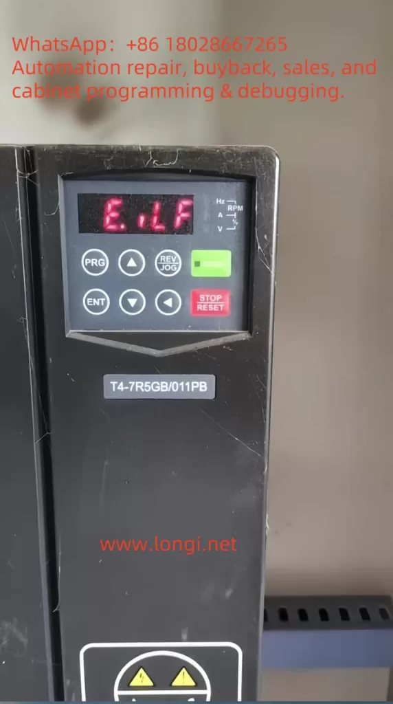
Variable Frequency Drives (VFDs), commonly known as frequency converters, are indispensable components in modern industrial automation systems. By adjusting the frequency and voltage of the input power supply, VFDs enable precise control of motor speed and torque, enhancing operational efficiency and significantly reducing energy consumption. The VEKONT C919 series, renowned for its high reliability and advanced features, has gained widespread adoption across various industrial applications. However, as with any complex electronic device, VFDs are susceptible to faults, with the “E.ILF” fault—indicative of an input phase loss—being a critical issue requiring immediate attention. This article delves into the essence of the E.ILF fault, explores its potential causes, and offers detailed solutions to help users restore normal operation, minimize downtime, and ensure optimal performance of the C919 series VFDs.
The Essence of the E.ILF Fault: Understanding Input Phase Loss
The E.ILF fault in the VEKONT C919 series VFD signals an abnormal condition where at least one phase of the three-phase input power supply is missing or not functioning properly. A three-phase power system consists of three alternating current phases, each separated by a 120-degree phase difference, providing a stable and balanced power input to the VFD. The VFD relies on this balanced supply to rectify the AC input into DC power, which is then inverted into variable-frequency AC power to drive the motor.
When one phase is lost—due to either an external power issue or an internal connection fault—the input power becomes unbalanced, potentially leading to the following complications:
- Voltage Imbalance: The remaining two phases may experience overvoltage or undervoltage, placing additional stress on the VFD’s internal components.
- Overcurrent Risk: The VFD may attempt to compensate for the missing phase by drawing excessive current through the remaining phases, leading to overheating or component damage.
- Abnormal Motor Operation: Due to the incomplete power supply, the driven motor may exhibit insufficient torque, increased vibration, or even fail to start.
The E.ILF fault represents a protective mechanism built into the C919 series VFD, designed to detect input phase loss and halt operation to prevent further damage to the equipment or motor. According to the manual on page 12, this fault can stem from various causes, which will be analyzed in detail below.
Possible Causes of the E.ILF Fault
Based on the fault table in the user manual, the E.ILF fault may arise due to the following four potential issues, each pointing to a distinct problem within the system:
1. Abnormal Three-Phase Input Power
This is the most common cause of an input phase loss fault. Abnormalities in the three-phase input power can result from:
- External Power Issues: Such as a phase outage in the power grid, blown fuses, or tripped circuit breakers.
- Wiring Problems: Loose, disconnected, or poor-contact connections between the power supply and the VFD.
- Upstream Equipment Failure: Faults in transformers or generators supplying power, which may result in the loss of one phase.
2. Drive Board Malfunction
The drive board is a critical component that controls the switching of power semiconductor devices (e.g., IGBTs) to facilitate energy conversion. If the drive board fails—due to aging components, overheating, or damage from electrical surges—it may fail to accurately detect or process one of the input phases, triggering the E.ILF fault.
3. Lightning Protection Board Malfunction
The lightning protection board safeguards the VFD against lightning strikes or transient voltage surges. If this board is damaged (e.g., due to a strike or prolonged wear), it may interfere with the normal detection of the input power or even damage the input circuit, leading to a false or actual phase loss fault.
4. Main Control Unit Anomaly
The main control unit serves as the “brain” of the VFD, coordinating overall operation and executing fault detection. If it malfunctions—due to firmware errors, hardware failures, or disrupted internal communication—it may misjudge the input power status, potentially triggering an E.ILF fault even when the three-phase supply is intact.
Steps to Resolve the E.ILF Fault
Addressing the E.ILF fault requires a systematic troubleshooting approach to identify the root cause and implement appropriate measures. Based on the manual’s recommendations to “check and eliminate issues in peripheral circuits” and “seek technical support,” the following detailed steps are proposed:
Step 1: Inspect and Eliminate Peripheral Circuit Issues
Begin by focusing on the external power supply and related circuits to ensure the three-phase input is functioning correctly. Specific actions include:
1. Verify Power Input
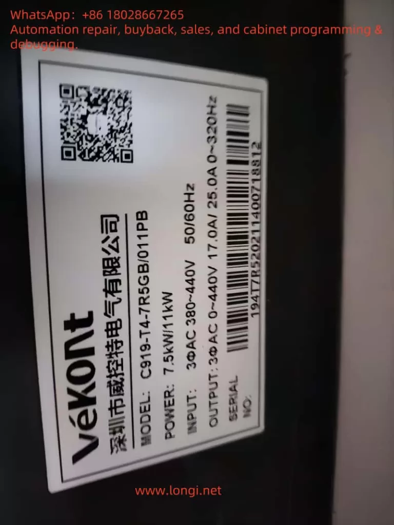
- Use a multimeter to measure the voltage across the VFD’s input terminals (L1, L2, L3), ensuring all three phases are balanced (typically within a 5% deviation) and within the C919 series’ rated range (e.g., 380V ±15%, as specified in the manual).
- Check the distribution panel for blown fuses or tripped breakers. Replace fuses or reset breakers as needed, and investigate the cause of tripping (e.g., short circuits or overloads).
- Inspect the wiring from the power source to the VFD for loose connections, breaks, or burn marks, ensuring all connections are secure and intact.
2. Check Upstream Equipment
- If the power is supplied by a transformer or generator, confirm these devices are operating normally and delivering a stable three-phase output.
- Use a power quality analyzer (if available) to detect issues like harmonics or voltage sags that might indirectly affect VFD performance.
3. No-Load Testing
- Disconnect the VFD from the motor load, power on the VFD alone, and observe whether the E.ILF fault persists. If the fault disappears, the issue may lie with the motor or load—e.g., a shorted winding or ground fault—requiring further motor inspection.
Step 2: Internal Troubleshooting and Technical Support
If the peripheral circuits are functioning normally but the fault persists, the issue may lie within the VFD itself. Proceed with caution and seek professional assistance when necessary. Initial troubleshooting steps include:
1. Inspect the Drive Board and Lightning Protection Board
- Power off the VFD, disconnect it from the power supply, and open the enclosure (ensure capacitors are discharged to avoid electrical shock).
- Examine the drive board and lightning protection board for visible damage, such as burnt components, swollen capacitors, or cracked solder joints. Replacement may be required if damage is found.
- Use a multimeter to test the continuity of key components (e.g., diodes and resistors) on the boards to confirm functionality.
2. Inspect the Main Control Unit
- Reset the VFD to factory settings as per the manual to rule out firmware or configuration errors.
- If the VFD includes diagnostic software or a display panel, run a self-diagnostic program to check for error codes in the main control unit.
- Verify that the firmware version is up to date, and contact the manufacturer for updates if needed.
3. Seek Technical Support
- If the above steps fail to resolve the issue, contact VEKONT technical support or a professional technician, providing a detailed fault description and troubleshooting results to expedite resolution.
- Depending on the extent of damage, replacement of the drive board, lightning protection board, main control unit, or even the entire VFD may be necessary.
Preventive Measures for E.ILF Faults
To reduce the likelihood of E.ILF faults, consider the following preventive measures:
- Regular Maintenance: Schedule periodic equipment inspections to test power stability, tighten connections, and remove dust or debris (e.g., spider webs visible in the provided photo, which could affect electrical contacts).
- Install Surge Protection: Add surge protection devices at the power input to ensure the internal lightning protection board functions effectively against lightning strikes or voltage surges.
- Monitor Power Quality: Use power quality monitoring equipment to promptly identify and address voltage imbalances or harmonic issues.
- Staff Training: Train maintenance personnel in the operation and troubleshooting of the C919 series VFDs to ensure rapid response to issues.
Conclusion
The E.ILF fault, or input phase loss fault, in the VEKONT C919 series VFD is a critical issue requiring timely intervention. Its essence lies in the imbalance of the three-phase input power supply, which can be caused by external power anomalies, drive board malfunctions, lightning protection board failures, or main control unit errors. By following a structured approach—starting with peripheral circuit checks and escalating to internal troubleshooting with technical support—users can effectively resolve the fault. Additionally, adopting preventive measures such as regular maintenance, surge protection, and power quality monitoring can significantly enhance the VFD’s long-term reliability. This article aims to provide practical guidance for C919 series users, ensuring efficient industrial production and equipment safety.