
I. Introduction to the Operation Panel Functions
1.1 Overview of the Operation Panel
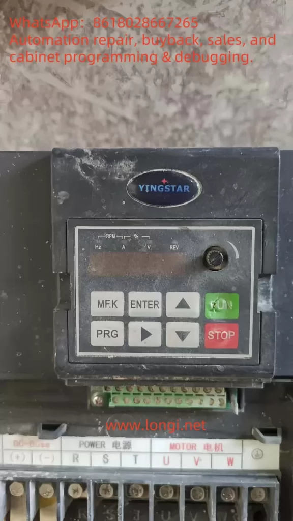
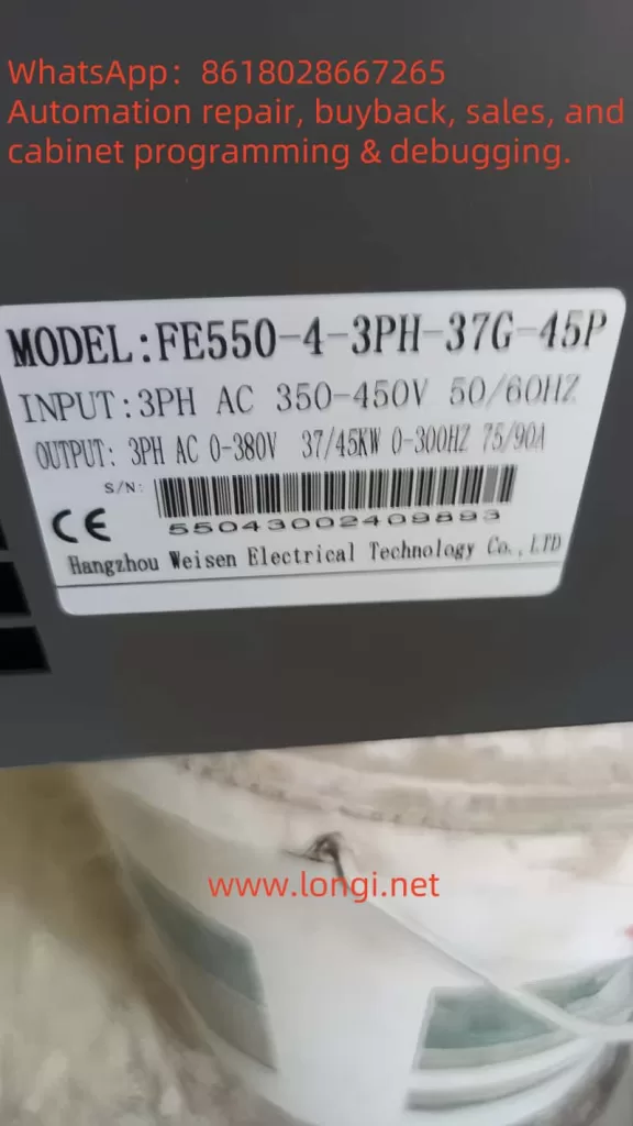
The operation panel of the Wisen Inverter FE550 integrates multiple functions, allowing users to set parameters, control operations, and diagnose faults through the buttons and display screen on the panel. The operation panel mainly includes the following parts:
- Display Screen: Used to display operating status, parameter values, and fault codes.
- Function Buttons: Including start, stop, frequency adjustment, and setting buttons.
- Navigation Buttons: Used to navigate through menus and select parameters.
1.2 How to Restore Factory Settings
In some cases, users may need to restore the inverter to its factory settings. Here are the steps to restore factory settings:
- Press the PROG button to enter the parameter setting mode.
- Use the ↑ or ↓ buttons to select parameter F0.50 (Parameter Restoration).
- Set F0.50 to 30 (Restore all factory parameters).
- Press the ENTER button to confirm, and the inverter will automatically restore to factory settings.
1.3 How to Encrypt and Unlock the Password
To prevent unauthorized parameter modifications, the FE550 series inverter supports parameter encryption. Here are the steps to encrypt and unlock the password:
Setting the Password:
- Enter the parameter setting mode and select parameter F0.36 (User Password).
- Enter a four-digit password (e.g., 1234) and press the ENTER button to confirm.
Unlocking the Password:
- When modifying parameters, the system will prompt for a password.
- Enter the correct password and press the ENTER button to unlock the password protection.
1.4 How to Set Parameter Access Restrictions
To further protect the inverter’s parameter settings, users can set parameter access restrictions:
- Enter the parameter setting mode and select parameter F0.36 (User Password).
- Set F0.36 to a non-zero value (e.g., 65555), indicating that the parameters are encrypted.
- In the parameter modification mode, only by entering the correct password can parameters be accessed and modified.
II. External Terminal Control and Speed Regulation Settings
2.1 External Terminal Forward/Reverse Control
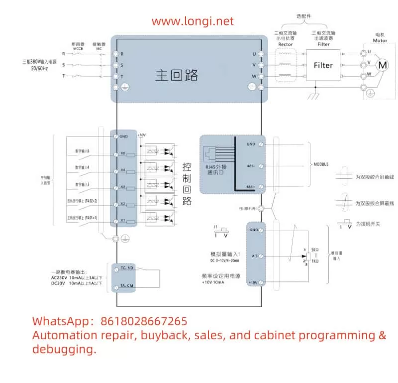
The FE550 series inverter supports forward/reverse control via external terminals. Here are the specific wiring and parameter setting steps:
Wiring Instructions:
- Forward Signal: Connect the external forward signal to the inverter’s X1 terminal.
- Reverse Signal: Connect the external reverse signal to the inverter’s X2 terminal.
- Common Terminal (GND): Connect the common terminal of the forward and reverse signals to the inverter’s GND terminal.
Parameter Settings:
- Enter the parameter setting mode, select parameter F4.01 (X1 Terminal Function Selection), and set it to 1 (Forward Operation).
- Select parameter F4.02 (X2 Terminal Function Selection) and set it to 2 (Reverse Operation).
- Save the settings, and the inverter will implement forward/reverse control based on the external terminal signals.
2.2 External Potentiometer Speed Regulation
The FE550 series inverter supports speed regulation via an external potentiometer. Here are the specific wiring and parameter setting steps:
Wiring Instructions:
- Potentiometer Signal: Connect the output signal of the external potentiometer to the inverter’s A15 terminal.
- Potentiometer Power Supply: Connect the positive pole of the external potentiometer’s power supply to the inverter’s +10V terminal and the negative pole to the GND terminal.
Parameter Settings:
- Enter the parameter setting mode, select parameter F0.02 (Main Frequency Command Selection), and set it to 5 (A15 Analog Input).
- Select parameter F5.14 (Maximum Input of Attached Potentiometer) and set it to the actual output voltage range of the potentiometer (e.g., 10V).
- Select parameter F5.15 (Maximum Input Corresponding Setting of Attached Potentiometer) and set it to 100.0% (indicating that the maximum input of the potentiometer corresponds to the inverter’s maximum frequency).
- Select parameter F5.16 (Filtering Time of Attached Potentiometer) and set it to 0.10s (adjust according to actual needs).
With the above settings, the inverter will adjust the output frequency based on the input signal from the external potentiometer, achieving speed regulation.
III. Fault Codes and Solutions
During operation, the FE550 series inverter may encounter various faults, which will be displayed as fault codes on the screen. Here are common fault codes and their solutions:
3.1 Common Fault Codes
| Fault Code | Fault Description | Possible Causes | Solutions |
|---|---|---|---|
| 1002 | Acceleration Overcurrent | Too short acceleration time, excessive load | Increase acceleration time, reduce load |
| 1003 | Deceleration Overcurrent | Too short deceleration time, excessive load | Increase deceleration time, reduce load |
| 1004 | Operating Overcurrent | Excessive load, motor fault | Check motor and load, reduce load |
| 1008 | Power Undervoltage | Input voltage too low | Check power supply voltage, ensure it is within the allowable range |
| 1010 | Inverter Overheating | High ambient temperature, poor heat dissipation | Improve heat dissipation conditions, reduce ambient temperature |
| 1016 | Communication Fault | Communication line or parameter error | Check communication line and parameter settings |
3.2 Fault Handling Steps
- Identify the Fault Code: View the fault code on the display screen to determine the fault type.
- Analyze the Cause: Analyze possible causes based on the fault code and description.
- Take Measures: Operate according to the solution to eliminate the fault.
- Verify Recovery: After troubleshooting, restart the inverter to confirm its normal operation.
IV. Conclusion
The Wisen Inverter FE550 series is a powerful and easy-to-operate inverter control device. Through proper wiring and parameter settings, users can achieve external terminal control, speed regulation functions, and efficient fault diagnosis. During use, it is recommended that users read the user manual carefully, follow the correct operation steps, and ensure the stable operation and long-term reliability of the device. If you encounter problems that cannot be solved, you can contact our technical support team for professional help and guidance.