
Introduction to the Operation Panel Functions
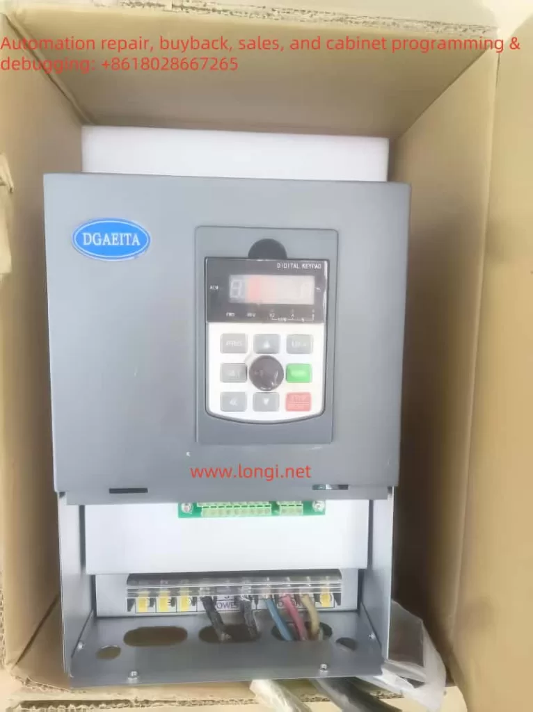
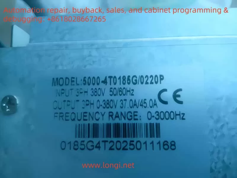
The operation panel of the 5000 Series DGAEITA frequency converter offers a range of functions for parameter setting, status monitoring, and operational control. Here is an overview of the main functions:
- Parameter Setting: The operation panel allows you to modify the functional parameters of the converter. The process uses a two-level menu structure: first, enter the function code menu, and then enter the parameter group menu to set specific parameters.
- Status Monitoring: The indicator lights and display screen on the operation panel provide real-time information about the converter’s operating status, fault status, and more. For example, the RUN light indicates that the converter is running, while the TUNE/TC light flashes slowly during tuning and quickly during a fault.
- Operational Control: The RUN and STOP/RESET buttons on the operation panel control the basic operations of the converter, such as starting and stopping.
Copying Parameters to Another Converter
To copy parameters from one converter to another, you can use the parameter backup and restore functions. Here are the steps:
- Backup Parameters: On the source converter, set the function code PP-01 to 4 to back up the current parameters.
- Restore Parameters: On the target converter, set the function code PP-01 to 5 to restore the backed-up parameters.
Setting Passwords and Parameter Access Restrictions
To protect the parameter settings of the converter, you can set a password and restrict parameter access. Here are the steps:
- Set Password: Set the function code P7-11 to a value between 0 and 32766 as the user password. After setting, you will need to enter the correct password each time you access the parameter settings.
- Parameter Access Restriction: Set the function code PP-04 to 1 to lock the parameters, making them unmodifiable. To modify the parameters, set PP-04 to 0.
Parameter Initialization
In some cases, you may need to reset the converter’s parameters to their factory settings. Here are the steps:
- Parameter Initialization: Set the function code PP-01 to 1 to restore factory parameters, excluding motor parameters. Set it to 3 to restore all parameters, including motor parameters.
External Terminal Control and Speed Adjustment
External Terminal Forward and Reverse Control
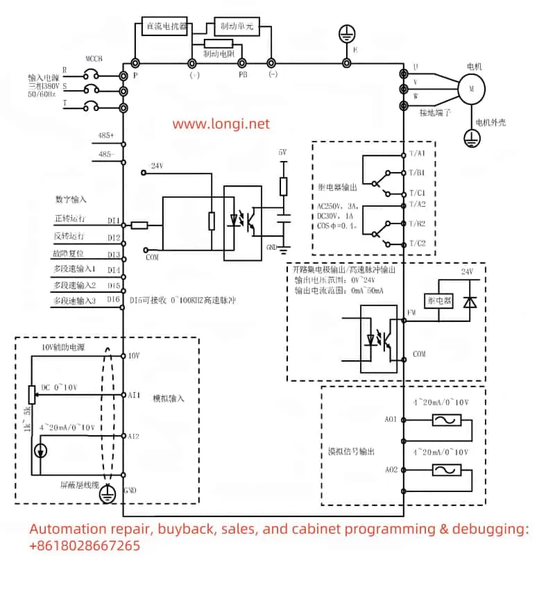
To enable external terminal control for forward and reverse operations of the converter, you need to set the relevant function codes and connect the wires. Here are the steps:
- Set Function Codes: Set the function code P4-00 to 1 (forward operation) and P4-01 to 2 (reverse operation).
- Wiring: Connect the external control signals to the DI1 and DI2 terminals of the converter. Closing DI1 will run the converter forward, and closing DI2 will run it in reverse.
External Potentiometer Speed Adjustment
To enable speed adjustment using an external potentiometer, you need to set the relevant function codes and connect the wires. Here are the steps:
- Set Function Codes: Set the function code P0-03 to 4 (keypad potentiometer).
- Wiring: Connect the signal line of the external potentiometer to the analog input terminals AI1 or AI2 of the converter.
- Set Analog Input Parameters: Set the function codes P4-13 to P4-16 to define the relationship between the analog input voltage and the frequency setting value.
Fault Codes and Handling
The 5000 Series DGAEITA frequency converter provides detailed fault codes to help users quickly identify and resolve issues. Here are some common fault codes, their meanings, and how to handle them:
- E015 (External Fault): This fault occurs when an external fault signal is sent to the converter. To resolve it, check the source of the external fault signal and address the issue. Once the fault is resolved, the converter can resume normal operation.
- E019 (Motor Parameter Learning Failure): This fault occurs when the converter fails to learn the motor parameters. To resolve it, check if the motor parameters are set correctly and ensure that the motor is disconnected from the load. Then, retry the learning process.
- E037 (Keypad Stop Fault): This fault occurs when the STOP/RESET key on the keypad is used to stop the converter in any control channel. To resolve it, check the wiring and status of the STOP/RESET key to ensure it is functioning correctly.
Conclusion
The user guide for the 5000 Series DGAEITA frequency converter provides comprehensive instructions for operating and maintaining the converter. By properly setting up the operation panel functions, copying and setting parameters, enabling external terminal control and speed adjustment, and understanding fault codes and their handling, users can efficiently manage the converter’s parameters, monitor its status, and troubleshoot issues. This ensures the stable and efficient operation of the converter.