
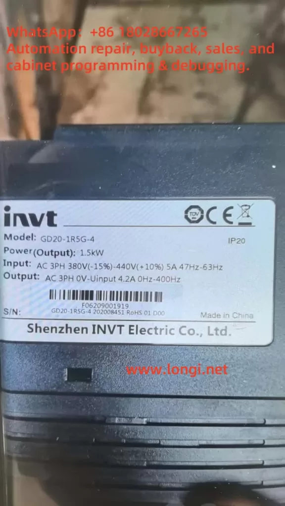
In industrial automation, multi-speed control is a practical and efficient method to handle varying load requirements using a Variable Frequency Drive (VFD). This article provides a step-by-step guide on configuring the INVT Goodrive20 series VFD to implement 3-wire (S1, S2, S3) multi-speed operation, suitable for up to 8 preset speed levels.
1. Control Principle
The Goodrive20 supports up to 16 speed levels, selectable through combinations of digital input terminals (S1 to S4). Each terminal acts as a binary bit, and the combination determines which speed level is active.
Using S1, S2, and S3, we can implement 8 speed levels (0–7):
| S3 | S2 | S1 | Speed Segment | Frequency Parameter |
|---|---|---|---|---|
| 0 | 0 | 0 | Segment 0 | P10.00 |
| 0 | 0 | 1 | Segment 1 | P10.01 |
| 0 | 1 | 0 | Segment 2 | P10.02 |
| 0 | 1 | 1 | Segment 3 | P10.03 |
| 1 | 0 | 0 | Segment 4 | P10.04 |
| 1 | 0 | 1 | Segment 5 | P10.05 |
| 1 | 1 | 0 | Segment 6 | P10.06 |
| 1 | 1 | 1 | Segment 7 | P10.07 |
Adding S4 (set as Multi-speed terminal 4) will expand the system to 16 segments (P10.00 ~ P10.15).
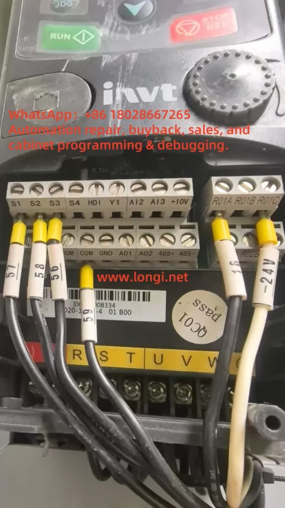
2. Wiring Overview
The terminals S1, S2, and S3 are digital input ports capable of receiving NPN or PNP signals from external switches, PLC outputs, or push buttons. By default, the control system uses an internal +24V supply, and the digital signals return to the PW common terminal.
3. Parameter Setup
Step 1: Set frequency source to Multi-Speed
P00.06 = 6 // Selects Multi-Speed as the frequency reference
Step 2: Assign S1, S2, S3 as Multi-Speed Inputs
Navigate to group P05, and configure input terminal functions:
| Parameter | Description | Value |
|---|---|---|
| P05.00 | S1 terminal function | 16 (Multi-speed terminal 1) |
| P05.01 | S2 terminal function | 17 (Multi-speed terminal 2) |
| P05.02 | S3 terminal function | 18 (Multi-speed terminal 3) |
If S4 is used:
P05.03 = 19 // S4 = Multi-speed terminal 4
Step 3: Configure Frequency Values for Each Segment
Set the desired frequency for each segment using parameters P10.00 ~ P10.07:
| Parameter | Segment | Example Value |
|---|---|---|
| P10.00 | 0 | 5.00 Hz |
| P10.01 | 1 | 10.00 Hz |
| P10.02 | 2 | 15.00 Hz |
| P10.03 | 3 | 20.00 Hz |
| P10.04 | 4 | 25.00 Hz |
| P10.05 | 5 | 30.00 Hz |
| P10.06 | 6 | 35.00 Hz |
| P10.07 | 7 | 40.00 Hz |
You may adjust values according to your application needs. Each value must be ≤ P00.03 (Max Output Frequency).
4. Operation Conditions & Notes
- The VFD must be running (Run command active) for multi-speed changes to take effect.
- Transitions between speed levels will follow acceleration/deceleration ramp settings.
- The default logic mode is NPN (sinking). If using PNP (sourcing) inputs, adjust the U-type jumper on the terminal board.
- Independent acceleration/deceleration times per segment can be configured in
P10.16 ~ P10.31. - If signal changes are sluggish, verify the input filter time via
P07.10.
5. Example Configuration (3-bit 8-Speed Control)
P00.06 = 6        // Frequency source = Multi-speed
P05.00 = 16       // S1 = Multi-speed terminal 1
P05.01 = 17       // S2 = Multi-speed terminal 2
P05.02 = 18       // S3 = Multi-speed terminal 3

P10.00 = 5.00     // Segment 0
P10.01 = 10.00    // Segment 1
P10.02 = 15.00    // Segment 2
P10.03 = 20.00    // Segment 3
P10.04 = 25.00    // Segment 4
P10.05 = 30.00    // Segment 5
P10.06 = 35.00    // Segment 6
P10.07 = 40.00    // Segment 7
6. Conclusion
The Goodrive20 VFD’s multi-speed functionality provides a robust method for achieving stepwise speed control using simple external switches or digital outputs. It is ideal for applications such as conveyors, fans, and pumps. With the correct parameter setup and terminal wiring, you can enable a highly flexible speed selection system without needing complex PLC programming.