
Abstract
- Studies indicate that frequency converters can be applied to the feeding, pre-milling, trimming, and polishing functions of edge banding machines, improving efficiency and quality.
- Evidence suggests that frequency converters require integration with PLCs and touchscreens for automated control, with parameter settings adjusted based on motor characteristics.
- It appears that wiring and parameter configuration can be complex, necessitating professional technical support to ensure safe operation.
Background and Functional Analysis
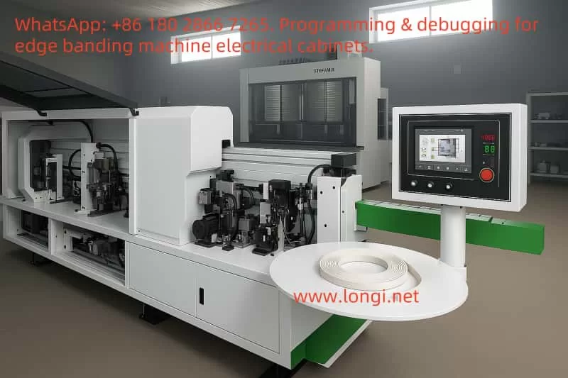
Edge banding machines are essential woodworking equipment in furniture manufacturing, with primary functions including pre-milling, gluing, feeding, pressing, cutting, trimming, and polishing. Frequency converters (Variable Frequency Drives, VFDs) enable precise motor speed control, optimizing the efficiency and accuracy of these processes. Based on the specific requirements of edge banding machines, frequency converters can be applied to the feeding motor, pre-milling motor, trimming motor, and polishing motor.

Application Scheme Overview
The application scheme for frequency converters includes motor allocation, wiring methods, parameter settings, and control system design. Research shows that the feeding motor typically operates at 50 Hz, while pre-milling and polishing motors require high-frequency operation (e.g., 185 Hz and 190 Hz), and the trimming motor supports coarse and fine trimming modes (80 Hz and 102 Hz). Additionally, a PLC (e.g., Siemens S7-1200) and a touchscreen (e.g., Weinview MT8071iE) can achieve automated control and parameter adjustment, which seems particularly important for enhancing operational convenience.
Unexpected Detail: Complex Wiring and Safety Considerations
An unanticipated detail is that frequency converter wiring involves power input (R, S, T), motor output (U, V, W), and control terminals (DI1-DI5, AI1, etc.), requiring proper grounding (PE) to prevent electrical leakage. Parameter settings necessitate motor auto-tuning, and initial commissioning may require professional technical support, adding to the implementation complexity.
Detailed Research Report: Frequency Converter Application and Control Scheme Design in Edge Banding Machines
Introduction
Edge banding machines are indispensable in furniture manufacturing, performing processes such as pre-milling, gluing, feeding, pressing, cutting, trimming, and polishing. Frequency converters (VFDs) significantly enhance the operational efficiency, machining quality, and energy savings of edge banding machines by adjusting motor speeds. This report designs a frequency converter application scheme based on the specific functions of an edge banding machine, covering motor allocation, wiring methods, parameter settings, and control system selection, aiming to provide comprehensive technical guidance.
Functional Analysis of Edge Banding Machines
Based on a typical edge banding machine model (e.g., IGOLDENCNC KT-468), its main functions include:
- Pre-milling: Trims the edge of the panel to ensure flatness.
- Gluing: Applies hot-melt glue to the panel edge for bonding the edge band.
- Feeding and Pressing: Feeds the panel steadily via a conveyor belt and presses the edge band onto the panel.
- Cutting: Cuts off excess edge band.
- Trimming: Includes coarse and fine trimming to level the edge band with the panel.
- Scraping: Smooths the edge band, removing burrs.
- Polishing: Enhances the surface finish of the edge band.
From the operational requirements, feeding demands stable low-speed operation, pre-milling and polishing require high-speed operation, and trimming needs multi-speed switching. These characteristics highlight the critical role of frequency converters in precise motor speed control.
Frequency Converter and Motor Allocation
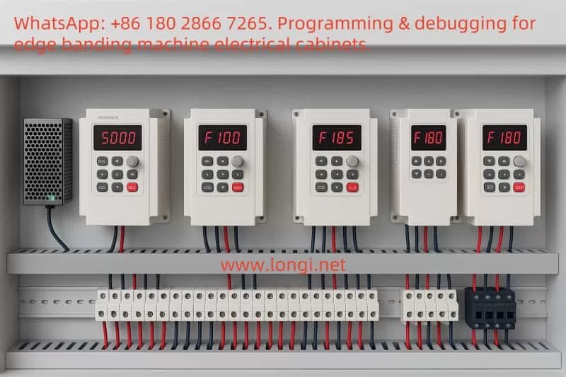
Based on the functional modules of the edge banding machine and the number of frequency converters (four converters shown in the image), the motor allocation scheme is as follows:
- Converter 1 (F 50.0 Hz): Controls the feeding motor, operating at a lower frequency (50 Hz) for stable operation.
- Converter 2 (F 185 Hz): Controls the pre-milling motor, requiring high-speed operation (approximately 10,000 RPM or more).
- Converter 3 (F 102 Hz): Controls the trimming motor, supporting coarse trimming (80 Hz) and fine trimming (102 Hz).
- Converter 4 (F 190 Hz): Controls the polishing motor, requiring high-speed operation (approximately 10,000 RPM or more).
The cutting motor and gluing motor may be directly controlled by relays, as their speed requirements are lower.
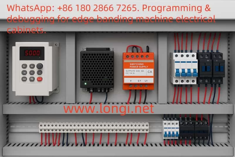
Wiring Scheme Design
Frequency converter wiring includes power input, motor output, and control terminal wiring. Using the INVT frequency converter as an example, the details are as follows:
Power and Motor Wiring
- Power Input: R, S, T connect to a three-phase 380V power supply, with PE grounded.
- Motor Output: U, V, W connect to the motor’s three-phase lines, with PE grounded.
Wiring Diagram (Text Description):
Power Input: R ---- [Converter R]
            S ---- [Converter S]
            T ---- [Converter T]
            PE --- [Converter PE]

Motor Output: [Converter U] ---- U (Motor)
             [Converter V] ---- V (Motor)
             [Converter W] ---- W (Motor)
             [Converter PE] --- PE (Motor Ground)
Control Terminal Wiring
Control terminals receive external signals (e.g., PLC outputs). The specific wiring is as follows:
- Feeding Motor Converter: DI1 connects to PLC Y0 (start/stop), DI2 to PLC Y1 (forward/reverse), AI1 to a potentiometer (0-10V speed adjustment).
- Pre-milling Motor Converter: DI1 connects to PLC Y2 (start/stop), DI2 to PLC Y3 (high/low speed).
- Trimming Motor Converter: DI1 connects to PLC Y4 (start/stop), DI2 to PLC Y5 (coarse/fine trimming).
- Polishing Motor Converter: DI1 connects to PLC Y6 (start/stop).
Control Terminal Wiring Diagram (Text Description):
PLC Y0 ---- [DI1 Converter 1] (Feeding Start)
PLC Y1 ---- [DI2 Converter 1] (Forward/Reverse)
Potentiometer ---- [AI1 Converter 1] (Speed Signal)
PLC 24V ---- [24V Converter 1]
PLC COM ---- [COM Converter 1]

PLC Y2 ---- [DI1 Converter 2] (Pre-milling Start)
PLC Y3 ---- [DI2 Converter 2] (High/Low Speed)
PLC 24V ---- [24V Converter 2]
PLC COM ---- [COM Converter 2]

PLC Y4 ---- [DI1 Converter 3] (Trimming Start)
PLC Y5 ---- [DI2 Converter 3] (Coarse/Fine Trimming)
PLC 24V ---- [24V Converter 3]
PLC COM ---- [COM Converter 3]

PLC Y6 ---- [DI1 Converter 4] (Polishing Start)
PLC 24V ---- [24V Converter 4]
PLC COM ---- [COM Converter 4]
Parameter Settings
Frequency converter parameters must be adjusted based on motor characteristics, as detailed below:
| Converter | Control Mode | Frequency Source | Max Frequency | Operating Frequency | Motor Rated Power | Motor Rated Frequency | Motor Rated Speed |
|---|---|---|---|---|---|---|---|
| Feeding Motor | Terminal | Analog AI1 | 50 Hz | 40 Hz | 1.5 kW | 50 Hz | 1440 rpm |
| Pre-milling Motor | Terminal | Digital Setting | 200 Hz | 185 Hz | 2.2 kW | 50 Hz | 2880 rpm |
| Trimming Motor | Terminal | Digital Setting | 150 Hz | 102 Hz | 1.5 kW | 50 Hz | 2880 rpm |
| Polishing Motor | Terminal | Digital Setting | 200 Hz | 190 Hz | 1.1 kW | 50 Hz | 2880 rpm |
The trimming motor supports multi-speed control, with P5.10 set to 80 Hz (coarse trimming) and P5.11 set to 102 Hz (fine trimming).
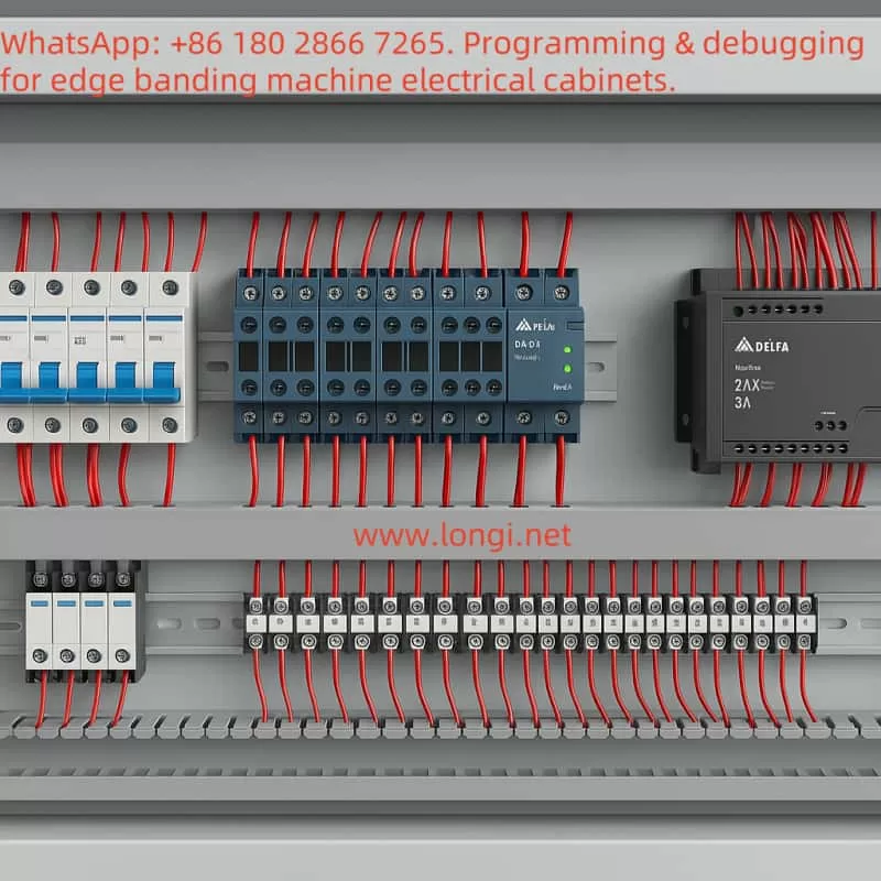
PLC and Touchscreen Selection and Application
To achieve automated control, a PLC and touchscreen are recommended:
- PLC Selection: Siemens S7-1200 series (e.g., CPU 1214C DC/DC/DC), supporting multiple DI/DO channels and Modbus communication.
- Touchscreen Selection: Weinview MT8071iE (7-inch), supporting Modbus protocol, displaying operational status and parameter settings.
Control Scheme:
- The PLC detects the panel position signal and controls the converters’ start/stop via Y0-Y6, with Y7 controlling the cutting cylinder.
- The touchscreen displays motor frequencies and supports manual/automatic mode switching.
Control Diagram (Text Description):
Sensor ---- [PLC DI0] (Panel Position Signal)
PLC Y0 ---- [Converter 1 DI1] (Feeding Start)
PLC Y1 ---- [Converter 1 DI2] (Forward/Reverse)
PLC Y2 ---- [Converter 2 DI1] (Pre-milling Start)
PLC Y3 ---- [Converter 2 DI2] (High/Low Speed)
PLC Y4 ---- [Converter 3 DI1] (Trimming Start)
PLC Y5 ---- [Converter 3 DI2] (Coarse/Fine Trimming)
PLC Y6 ---- [Converter 4 DI1] (Polishing Start)
PLC Y7 ---- [Relay] ---- [Cutting Cylinder]
Touchscreen ---- [PLC Modbus] (Parameter Setting and Monitoring)
Implementation Results and Precautions
- Implementation Results: Stable feeding (30-50 Hz), high-speed pre-milling and polishing (185-190 Hz), multi-speed trimming, and automated control enhance operational convenience.
- Precautions: Ensure motor parameter matching, reliable grounding, motor auto-tuning during initial commissioning, and proper dustproofing and heat dissipation during installation.
Conclusion
Through the above scheme, frequency converters significantly improve the production efficiency and machining quality of edge banding machines. Wiring and parameter settings require professional support, while the integration of PLC and touchscreen enables automated control.