
Introduction
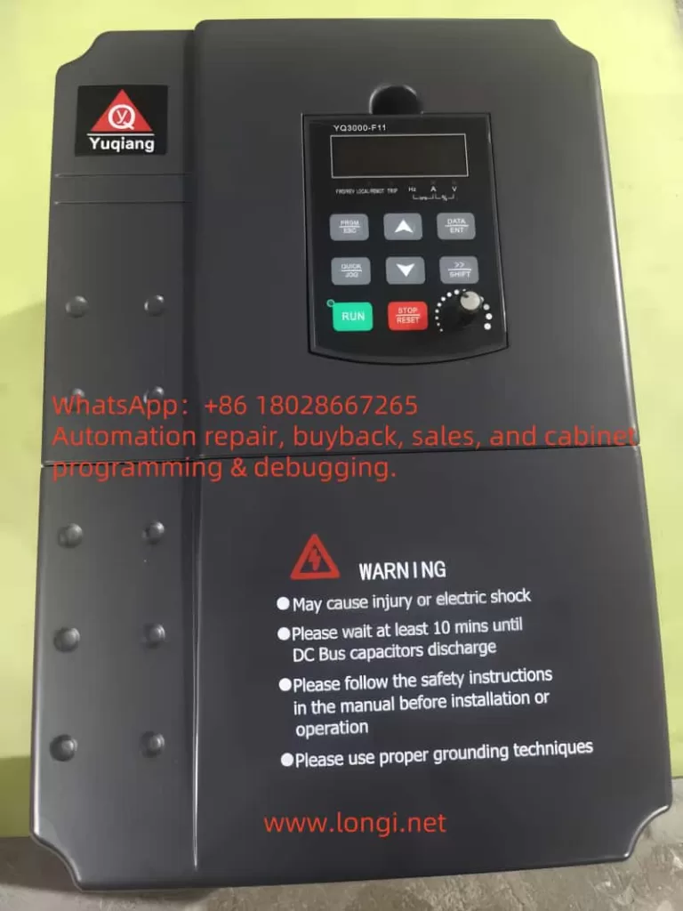
In industrial automation and control systems, Variable Frequency Drives (VFDs) are indispensable core devices. They convert fixed-frequency AC power into variable-frequency AC power, enabling precise control over the speed and torque of AC motors. This functionality is crucial in various fields, including manufacturing, Heating, Ventilation, and Air Conditioning (HVAC), and water pump systems. The Yuqiang YQ3000-G11 frequency converter, manufactured by Foshan Yuqiang Electromechanical Co., Ltd., is widely popular in the market for its reliability and high performance. However, like any electronic device, it may encounter faults, with the SPO fault (Output Phase Loss) being one of the common issues faced by YQ3000-G11 users. This article delves into the nature, causes, solutions, and preventive measures of the SPO fault, providing comprehensive guidance to ensure efficient and stable system operation.
Definition and Manifestation of SPO Fault
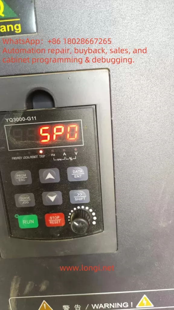
The SPO fault is displayed as “SPO” or “5P0” on the control panel of the YQ3000-G11 frequency converter, accompanied by the illumination of the “TRIP” indicator light. This indicates that the frequency converter has detected the absence of at least one phase or severe imbalance in the three-phase (U, V, W) output load. According to the provided diagnostic table (attached “image.png”), the SPO fault is described as “U, V, W phase loss output (or severe three-phase load asymmetry),” advising users to “check output wiring; check motor and cables.” This fault prevents the motor from starting or operating normally, potentially leading to overheating, inefficiency, and even damage to the motor or frequency converter.
In a three-phase power system, the U, V, and W phases must remain balanced to ensure proper motor operation. A phase loss means the absence of voltage or current in one phase, causing an imbalance in the three-phase system. This situation may manifest as:
- Unstable motor operation, with抖动 (vibration) or abnormal noise.
- Inability of the motor to reach the expected speed or power output.
- Automatic shutdown of the frequency converter to protect the system, displaying the SPO fault code.
Nature of SPO Fault
The essence of the SPO fault is the imbalance or absence of three-phase power on the output side of the frequency converter. This anomaly can be caused by several factors:
Wiring Issues:
- Loose or disconnected output cables, preventing normal power transmission in one phase.
- Damaged cables, such as wear, burnout, or breakage.
- Wiring errors, such as incorrect connection of the U, V, W phase sequence or improper connection.
Motor Issues:
- Open circuit in the motor windings, preventing a complete circuit in one phase.
- Internal short circuit or insulation damage in the motor, affecting current balance.
- Loose or damaged motor connection terminals.
Internal Frequency Converter Faults:
- Damaged Insulated Gate Bipolar Transistor (IGBT) modules, affecting the output of one phase.
- Control circuit or drive board faults, leading to abnormal output signals.
- Internal overvoltage or overheating protection triggering, suspending output.
External Factors:
- Overloading, exceeding the rated capacity of the frequency converter or motor.
- Environmental factors, such as high temperature, high humidity, or dust accumulation, affecting device performance.
- Grid voltage fluctuations or interference, potentially indirectly affecting output stability.
Parameter Setting Issues:
- Improper setting of the phase loss protection threshold in the frequency converter, which may be overly sensitive or incorrectly configured.
- Mismatch between other parameters (such as current limit or frequency setting) and the actual load.
These causes may occur individually or in combination, leading to the occurrence of the SPO fault. Understanding the nature of the fault helps users quickly locate the problem and take effective measures.
Solutions for SPO Fault
Resolving the SPO fault requires a systematic troubleshooting approach. The following is a detailed diagnostic and repair process:
Step 1: Check Output Wiring
- Inspect Cable Condition: Carefully examine the U, V, and W phase cables from the frequency converter to the motor for signs of wear, burnout, or breakage.
- Confirm Secure Connections: Ensure all wiring terminals are tightened and free from looseness or poor contact.
- Verify Wiring Correctness: Refer to the YQ3000-G11 frequency converter manual (attached “YQ3000-G11 Yuqiang Frequency Converter Manual.pdf”) to confirm the correct connection of the U, V, and W phase sequence.
Step 2: Check Motor
- Measure Winding Resistance: Use a multimeter to measure the resistance between U-V, V-W, and W-U on the motor. Normally, the resistance of each phase should be close and balanced. Significant differences may indicate an open circuit or damage to the windings.
- Check for Short Circuits: Test for continuity between each phase and ground to ensure no short circuits exist.
- Disconnect Motor Test: Disconnect the motor from the frequency converter, run the frequency converter, and measure the output voltage. If the fault disappears, the problem may lie with the motor or load.
Step 3: Verify Frequency Converter Output
- No-Load Test: With the motor disconnected, start the frequency converter and use a multimeter to measure the output voltage between U-V, V-W, and W-U. Normally, the three-phase voltage should be balanced and conform to the frequency converter specifications.
- Check for Internal Faults: If the output voltage is unbalanced or missing, it may indicate an IGBT module or control circuit fault. Further hardware inspection or contact with professional maintenance personnel is required at this point.
Step 4: Check Load and Environment
- Confirm Load Matching: Ensure the connected load is within the rated capacity of the frequency converter and motor. Overloading may trigger protection mechanisms, leading to the SPO fault.
- Check Environmental Conditions: Confirm that the operating environment temperature and humidity of the frequency converter are within the recommended ranges (refer to the manual). High temperatures or humidity may cause component performance degradation.
Step 5: Check Parameter Settings
- Enter Parameter Settings: Access the parameter settings menu through the control panel (attached “spo.jpg”) and check parameters related to phase loss protection.
- Adjust Thresholds: Ensure the phase loss protection threshold is suitable for the current application and adjust it if necessary.
- Restore Factory Settings: If unsure about the parameter configuration, try restoring the factory settings and reconfiguring them.
Step 6: Seek Professional Help
- If the above steps fail to resolve the issue, it is recommended to contact us for technical support.
- For internal hardware faults (such as IGBT module damage), professional technicians using specialized tools are required for repair or replacement.
Fault Troubleshooting Flowchart
| Step | Inspection Content | Tools | Expected Results |
|---|---|---|---|
| 1 | Check output cables | Visual inspection, screwdriver | Cables undamaged, connections secure |
| 2 | Measure motor winding resistance | Multimeter | Balanced three-phase resistance, no short circuits |
| 3 | Test frequency converter output voltage | Multimeter | Balanced three-phase voltage, conforming to specifications |
| 4 | Check load and environment | Ammeter, thermometer | Load within rated range, suitable environment |
| 5 | Check parameter settings | Control panel | Correct parameter configuration |
| 6 | Contact professional support | Phone/email | Obtain further guidance or repair |
Preventive Measures
To reduce the occurrence of SPO faults and extend the service life of the YQ3000-G11 frequency converter, the following preventive measures can be taken:
Regular Maintenance:
- Inspect and tighten all electrical connections quarterly.
- Regularly clean the frequency converter and motor to prevent dust accumulation leading to overheating.
Proper Installation:
- Install the frequency converter in a well-ventilated area away from high temperatures and humidity.
- Use high-quality cables and connectors that meet specifications.
Load Management:
- Ensure the motor load is within the rated range to avoid overloading.
- Use soft start or progressive acceleration functions to reduce electrical shock during startup.
Monitoring System:
- Install monitoring equipment to track frequency converter performance in real-time and detect anomalies promptly.
- Regularly review fault logs to address potential issues.
Training and Documentation:
- Train operators to ensure they are familiar with the correct use and basic troubleshooting of the frequency converter.
- Keep the frequency converter manual (attached “YQ3000-G11 Yuqiang Frequency Converter Manual.pdf”) for easy reference.
Conclusion
The SPO fault is a common issue that may be encountered during the operation of the Yuqiang YQ3000-G11 frequency converter. Its essence is the absence or imbalance of three-phase power on the output side, which may be caused by wiring issues, motor faults, internal frequency converter problems, or external factors. Through systematic troubleshooting steps, such as checking wiring, motor, output voltage, and parameter settings, users can effectively diagnose and resolve the fault. Regular maintenance, proper installation, and load management are key measures to prevent SPO faults. For further assistance, it is recommended to refer to the manual or contact the technical support team of Yuqiang Electromechanical. By taking these measures, users can ensure the stable operation of the frequency converter system, maximizing equipment lifespan and production efficiency.