Posted on Leave a comment

SEW MOVIMOT MM D Series “ERROR 07” Fault Analysis and Solution

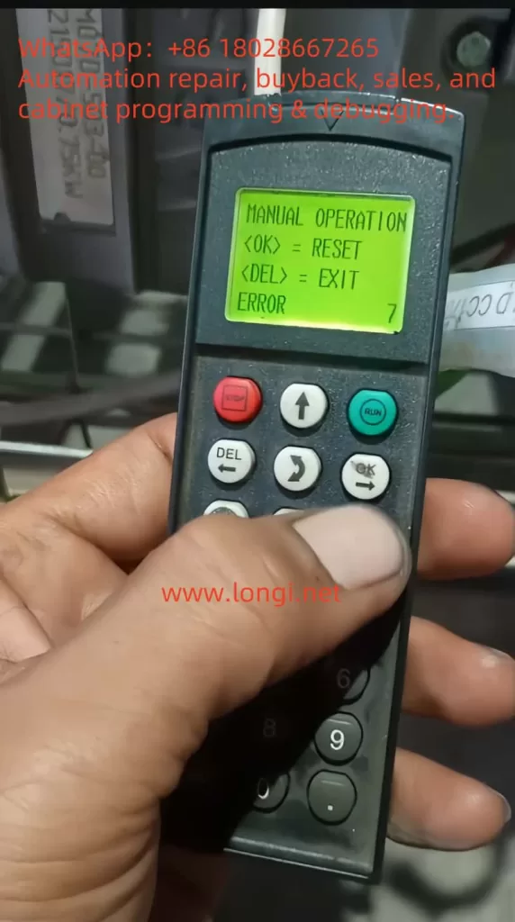
1. Meaning of ERROR 07 Fault Code

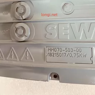
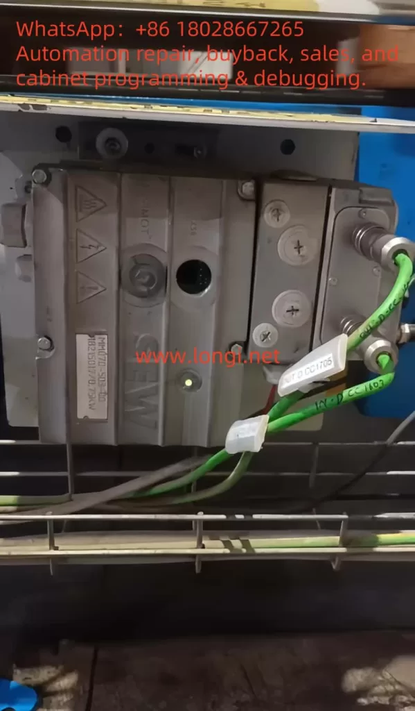
When the SEW-EURODRIVE MOVIMOT MM D series servo drive displays “ERROR 07,” it indicates “DC link voltage too high.” This fault typically occurs when the DC link voltage exceeds its rated range. According to the manual, the appearance of ERROR 07 can be caused by several factors, including short ramp times, faulty connections between the braking resistor and brake coil, incorrect internal resistance of the brake coil or braking resistor, thermal overload of the braking resistor, and invalid input voltage.

ERROR 7

1.1 Ramp Time Too Short

If the ramp time is set too short, the voltage in the DC link can rise too quickly, triggering the ERROR 07 fault. The ramp time controls the speed at which the drive accelerates. If the ramp time is too short, it can cause excessive current and voltage variations, leading to this fault.

1.2 Faulty Connection Between Brake Coil and Braking Resistor

The braking resistor and brake coil are crucial for controlling the DC link voltage during braking. If there is a poor connection between the brake coil and braking resistor, energy from braking cannot be absorbed effectively, causing the DC link voltage to rise too high and triggering ERROR 07.

1.3 Incorrect Internal Resistance of Brake Coil/Braking Resistor

The internal resistance of the brake coil or braking resistor must be within specific limits to effectively control braking energy. If the resistance deviates from the required value, the braking system will not function properly, and the DC link voltage may increase, causing ERROR 07.

1.4 Thermal Overload of the Braking Resistor

If the braking resistor is undersized or overloaded, it can overheat, leading to excessive DC link voltage. In such cases, the braking resistor must be properly sized to withstand the required braking torque and power without overheating.

1.5 Invalid Voltage Range of Supply Input Voltage

The input voltage to the drive must remain within its specified range. If the input voltage exceeds this range, it can lead to an excessively high DC link voltage. It is essential to verify that the supply voltage is within the permissible range as specified by the drive.

2. Solutions

Depending on the root cause of the ERROR 07 fault, here are the detailed diagnostic steps and solutions:

2.1 Extend the Ramp Time

If the ramp time is too short, you can extend it to allow the voltage to rise more gradually. Increasing the ramp time helps prevent the voltage from increasing too quickly, which could trigger the fault.

Steps:

  • Enter the drive’s configuration menu.
  • Find the ramp time parameter (typically labeled as “Ramp Time”).
  • Increase the ramp time to a value that allows the voltage to rise at a safe rate.
  • Save the settings and restart the drive to check if the fault is resolved.

2.2 Check the Connection Between the Brake Coil and Braking Resistor

If the connection between the braking resistor and brake coil is faulty, check all connection points to ensure they are secure and not loose or disconnected. If there is a problem, repair or replace the connection.

Steps:

  • Turn off the drive and disconnect the power.
  • Inspect the connections between the brake coil and braking resistor for any loose or broken connections.
  • Reconnect any faulty connections to ensure they are secure.
  • Power on the drive and test if the fault is cleared.

2.3 Check and Adjust the Internal Resistance of the Brake Coil/Braking Resistor

The internal resistance of the brake coil and braking resistor should match the required specifications. Use a multimeter to measure the resistance and compare it with the specifications in the drive’s technical manual.

Steps:

  • Use a multimeter to measure the resistance of the brake coil or braking resistor.
  • Compare the measured resistance with the recommended value in the technical data section of the manual.
  • If the resistance is incorrect, replace the brake coil or braking resistor with a new one that meets the specifications.

2.4 Properly Size the Braking Resistor

If the braking resistor is overloaded or improperly sized, it can cause thermal overload and lead to ERROR 07. The braking resistor should be able to absorb the energy produced during braking without overheating. Replace the braking resistor with one of the correct size.

Steps:

  • Calculate the required power and torque for the braking resistor based on the drive’s load.
  • Choose a braking resistor with sufficient power rating to handle the braking energy without overheating.
  • Install the appropriately sized braking resistor and test the drive to confirm the fault is resolved.

2.5 Check the Input Voltage

If the input voltage exceeds the rated range of the drive, it may cause an excessive DC link voltage. Use a multimeter to check that the supply voltage is within the allowable range. If the voltage is too high, consider adjusting the power supply or replacing it with one that provides the correct voltage.

Steps:

  • Use a multimeter to measure the input voltage to the drive.
  • Ensure the voltage is within the rated range specified for the drive (typically 380V to 500V AC).
  • If the input voltage is too high, check the power supply and adjust or replace it as necessary.

MM07D-503

3. Preventive Measures to Avoid ERROR 07

To prevent ERROR 07 from recurring, the following measures can be taken:

3.1 Regularly Check and Maintain the Braking System

Regularly inspect the braking resistor and brake coil for proper connections and resistance values. Ensure that they meet the required specifications to avoid issues with braking performance.

3.2 Optimize Cooling and Ventilation

Ensure the drive is installed in a well-ventilated area to prevent overheating. Regularly clean the drive’s cooling fins and ensure there are no obstructions blocking airflow. Keeping the drive cool will help avoid thermal overload issues.

3.3 Properly Size the Braking Resistor

Always select the correct size of braking resistor based on the load requirements. Ensure the braking resistor can handle the required braking torque and power without overheating.

3.4 Monitor Input Voltage Stability

Monitor the input voltage to ensure it remains within the permissible range. Using a stable power supply that provides consistent voltage within the rated range will help prevent issues with the DC link voltage.


4. Conclusion

The SEW MOVIMOT MM D series servo drive is an essential component in modern automation systems. The ERROR 07 fault, which occurs due to high DC link voltage, can be caused by several factors such as short ramp times, faulty braking system connections, incorrect internal resistance, thermal overload of the braking resistor, or invalid input voltage. By following the diagnostic steps and solutions outlined above, you can effectively address and resolve this issue. Regular maintenance, proper configuration, and careful monitoring of the drive’s operation will ensure long-term reliability and optimal performance.


Posted on Leave a comment

Working Principle and Application Guide of YT-3300 Smart Valve Positioner

The YT-3300 series from Rotork YTC is a high-performance electro-pneumatic smart valve positioner widely applied in industries such as petrochemical, power, pharmaceuticals, and process automation. It receives a 4-20 mA analog current signal from PLC or DCS, processes it through a built-in PID controller, and converts it into a pneumatic signal to precisely drive valve actuators. The unit also supports HART communication and optional feedback output (4-20 mA or digital) for closed-loop control.

This article explains its operating principle, core functions, product features, selection criteria, and usage guidelines in detail.

YT-3300

1. Working Principle

The YT-3300 receives a 4-20 mA signal (HART optional) representing the desired valve position. An internal 12-bit ADC samples the current and compares it to the actual valve position measured by an integrated travel sensor (either a magnetic resistance sensor or potentiometer). The PID controller calculates the necessary correction.

The output is then handled by an internal I/P (current-to-pressure) converter using a nozzle-flapper mechanism and miniature solenoid valves. The result is two precisely controlled pneumatic outputs (OUT1 / OUT2), used to actuate single- or double-acting pneumatic actuators.

The travel sensor’s reading can also be converted to a 4-20 mA signal or a digital communication protocol (e.g., HART, FF, PA) for remote monitoring.


2. Block Diagram (Closed-loop control)

      4-20 mA Input ─┐
                     ▼
  +------------------------------+
  | PID Controller + PWM Driver |
  +------------------------------+
           │            ▲
           ▼            │
  Miniature I/P Valve   │ Travel Sensor
           │            │ (NCS / Potentiometer)
           ▼            │
     OUT1 / OUT2 Pneumatic Output
           │
           ▼
  Pneumatic Actuator (Single/Double)

3. Key Functions

  • Digital PID Control: High-precision positioning within ±0.5% F.S.
  • Auto Calibration: AUTO1 / AUTO2 scan modes for fast commissioning.
  • Split Range Support: 4–12 mA / 12–20 mA assignment.
  • Feedback Options: 4-20 mA feedback (PTM module), mechanical limit switch (LSi), HART/FF/PA digital output.
  • Self-Diagnosis: Error codes such as OVER CUR, RNG ERR, or C ERR displayed on LCD screen.
  • Manual/Auto Switch: Supports bypass operations during maintenance.

4. Product Features

  • Integrated PID + I/P + feedback + diagnostics in one unit.
  • Compatible with both linear and rotary actuators.
  • IP66/NEMA 4X enclosure with explosion-proof or intrinsically safe options.
  • Supports SIL2/3 safety systems.
  • Maintenance-free NCS sensor and remote sensor options for high-temp or vibration zones.

5. Model Selection Guide

Code PositionOptionDescription
1L / RLinear or Rotary Actuator
2S / DSingle or Double Acting
3N / i / A / ENo Explosion / Intrinsically Safe
40 / 2 / F / PNone / HART / FF / PA Communication
51 / 2 / …PTM (Feedback) / LSi (Limit Switch)

Examples:

  • YT-3300RDN1101S: Rotary, double acting, no feedback, no HART.
  • YT-3300LSi-1201S: Linear, single acting, with 4-20 mA feedback + limit switch.

YT-3300 Wiring Block Diagram

6. Installation & Usage

Mechanical:

  • Ensure linkage lever aligns perpendicular at 50% stroke.
  • Use Namur bracket for rotary actuator mounting.

Pneumatics:

  • Use clean, dry air (0.14–0.7 MPa); OUT1 for single-acting, both OUT1/OUT2 for double-acting.

Electrical:

  • IN+ to signal source; IN– to common.
  • PTM feedback must use a separate loop.

Calibration:

  • Hold [MODE] to enter AUTO1.
  • Recalibrate using AUTO2 if positioning errors > 5%.
  • Adjust PID or Deadzone if valve hunts or is sluggish.

7. Common Faults

CodeDescriptionFix
OVER CURInput > 24 mACheck wiring, short circuit
RNG ERRStroke out of rangeRecalibrate or adjust lever
C ERRControl deviation too bigCheck air supply, valve jam

8. Application Scenarios

  • Control valves in chemical reactors
  • LNG valve control under sub-zero conditions
  • SIL-rated ESD valve systems
  • Remote installations requiring non-contact sensors

9. Conclusion

The YT-3300 series combines intelligent PID control, precise I/P conversion, diagnostics, and multiple feedback options into one robust, compact unit. Its flexibility in communication (analog or digital), safety compliance, and rugged design make it a superior choice for modern valve automation.


Posted on Leave a comment

In-Depth Fault Analysis: Understanding “Drift + Half-Drift + Amplification” Combined Errors in ABB Continuous Gas Analyzers and How to Resolve Them

1. Overview and Error Description

During operation of ABB’s AO2000 series continuous gas analyzers (such as Fidas24, Magnos, etc.), the following error message may be displayed:

ERROR  
A combination of Drift,  
Half‑Drift and Amplification errors occurred!  
02 → ESC

This message indicates that the analyzer has simultaneously detected three types of offset-related faults: Drift, Half-Drift, and Amplification errors. When these faults are combined, the system flags a critical failure (error code 507/02), potentially halting analysis and rejecting calibration until the issue is resolved.


EL3020 ERROR

2. Explanation of Each Error

  • Drift Error: Occurs when the signal offset exceeds acceptable thresholds, indicating a deviation of the baseline from its expected value.
  • Half-Drift: Triggered when the drift exceeds 50% of the allowed range — considered a warning-level error.
  • Amplification Error: Involves abnormal gain changes where the signal is either over-amplified or under-amplified, making measurement inaccurate.

A combined error suggests the presence of multiple overlapping issues, usually triggering a safety lock to prevent invalid measurements or faulty gas composition reports.


3. Root Causes of Combined Error

To understand the fault comprehensively, we must examine it from the sensor behavior, calibration process, and environmental conditions:

a) Sensor Aging or Degradation

Infrared, paramagnetic, or thermal conductivity sensors may suffer from aging, leading to unstable offsets and signal gain. Optical sources, sample cells, and pre-amplifiers may degrade over time and trigger drift.

b) Environmental or Sampling Issues

Contaminated sampling lines (moisture, oil mist, or particulate matter) can distort calibration by affecting gas composition. Humidity and temperature fluctuations also contribute to drift and amplification failures.

c) Calibration Gas or Flow Irregularities

Inconsistent span or zero gas flow, or expired gas bottles, can lead to calibration errors. When calibration fails multiple times, the analyzer may flag this combined drift/amplification condition.


Normal display status of EL3020

4. Fault Classification and Corrective Actions

Fault TypeManifestationRecommended Action
Drift / Half-DriftBaseline deviation or slow measurement responseCheck drift logs and compare to tolerance
Amplification ErrorGain factor changes sharply from historical levelsEvaluate sensor electronics or pre-amp
Combined Error 507Calibration fails; analyzer halts measurementTrigger manual calibration and inspect logs
Environmental ImpactErrors repeat in humid/contaminated environmentsClean lines, dry filters, verify sample gas

5. Step-by-Step Troubleshooting Guide

Step 1: View Diagnostic Readings

Access the analyzer menu and retrieve drift, gain, and error logs. Compare with baseline values and specifications.

Step 2: Inspect and Clean Sampling System

  • Replace or clean sample tubing, filters, or water traps.
  • Verify that the calibration gas is flowing correctly and meets purity specifications.

Step 3: Perform Manual Calibration

Access maintenance mode and carry out a full zero/span calibration. If the system fails again:

  • Check whether the instrument is actually drawing calibration gas.
  • Monitor flowmeter readings and solenoid valve actuation.

Step 4: Component-Level Inspection

  • Replace sensors, detector modules, or signal pre-amplifiers if values are unstable.
  • Check power supply stability and internal electronics.
  • Reboot analyzer after hardware check.

Step 5: Validate with Monitoring

After repairs, allow the instrument to stabilize and log drift values over 24 hours. Ensure both zero and span values hold within specification.


6. Preventive Maintenance Recommendations

  1. Daily Drift Monitoring: Log drift rates at least once per shift.
  2. Monthly or Quarterly Calibration: Use certified calibration gas bottles with verified expiration dates.
  3. Gas Path Dryness: Keep the system moisture-free using desiccants or active dryers.
  4. Sensor Lifecycle Tracking: Monitor installation date and replace sensors per manufacturer’s suggested intervals.
  5. Firmware and Software Updates: Regularly update analyzer software to address known error conditions and optimize calibration routines.

Internal structure diagram of EL3020

7. Case Study Example

A gas analyzer running for 6+ months triggered a combined 507 error. Drift values reached 180%, amplification deviation was excessive, and span calibration repeatedly failed. After inspection, the calibration gas flow had dropped significantly, and condensation was found in the sampling line.

Corrective action included replacing the filter, drying the line, and restoring gas flow. After performing a fresh zero/span calibration, the analyzer resumed normal operation.

This case confirms that calibration integrity and sample system hygiene are crucial for reliable performance.


8. Conclusion

  • Fault nature: This combined error involves overlapping sensor baseline drift, amplification gain deviation, and calibration failure.
  • Resolution:
    1. Review diagnostic metrics.
    2. Clean sampling path.
    3. Recalibrate manually.
    4. Replace modules if needed.
    5. Reboot and test.
    6. Establish a preventive maintenance protocol.
    7. Log and trend drift data periodically.

By maintaining proper calibration procedures, monitoring drift trends, and proactively replacing aging components, operators can avoid 507/02 combined faults and ensure high availability and accuracy from ABB EL3020 or AO2000 gas analyzers.


Note: This article assumes the presence of standard modules such as Uras26, Magnos206, or Fidas24. Detailed troubleshooting should be tailored to your specific analyzer configuration and environmental conditions.


Posted on Leave a comment

User Guide for MyGo Pro PCR Instrument

1. Principles, Functions, and Applications of MyGo Pro PCR Instrument

Principles

The MyGo Pro is a real-time quantitative PCR (qPCR) instrument based on the polymerase chain reaction (PCR) technology, enabling DNA or RNA amplification through thermal cycling. Its core technology is “Full Spectrum Optics,” which utilizes high-intensity LEDs (500 nm excitation) and a CMOS camera (510-750 nm detection) to collect fluorescence data from 120 optical channels in parallel from each reaction tube without moving parts, ensuring the reliability of multiplex PCR. Additionally, the MyGo Pro supports high-resolution melt (HRM) curve analysis, capable of distinguishing all types of single nucleotide polymorphisms (SNPs), including Class 4 SNPs.

MYGO PRO qPCR

Functions

The MyGo Pro offers the following key functions:

  • High Precision and Sensitivity: Single-copy detection, 9-log dynamic range, and 1.1-fold discrimination precision.
  • Multiplex PCR: Supports simultaneous analysis of at least 7 targets, each using a different fluorescent label.
  • Fast Thermal Cycling: Heating speed of 5°C/second, cooling speed of 4°C/second, with 45 cycles completed in approximately 33 minutes and total run time less than 40 minutes.
  • HRM Analysis: Efficiently distinguishes genetic variations by combining thermal control, optical data quality, and HRM data analysis.
  • Automated Analysis: Software supports absolute and relative quantification, melt curve analysis, endpoint genotyping, and HRM.

Technical Specifications

  • Thermal Uniformity: ±0.1°C
  • Thermal Accuracy: ±0.25°C
  • Temperature Range: 37-99°C
  • Optical Channels: 4 (for multiplexing), supporting 22 pre-calibrated dyes including SYBR Green I, FAM, ROX, etc.
  • Supported Detection Formats: TaqMan, Molecular Beacons, SimpleProbes®, Intercalators, HRM

The following table summarizes the main functions:

Function CategoryDetails
Detection SensitivitySingle-copy detection, 9-log dynamic range, 1.1-fold discrimination precision
Thermal Cycling SpeedHeating 5°C/second, cooling 4°C/second, 45 cycles in ~33 minutes
Optical System120 optical channels, 510-750 nm detection, CMOS camera
Supported DyesSYBR Green I, FAM, ROX, etc. (22 types)
Analysis ModulesAbsolute/relative quantification, melt curve, HRM, etc.

Applications

The MyGo Pro is widely used in:

  • Gene Expression Analysis: Detects 10% differences in transcript concentrations.
  • Pathogen Detection: Quantifies pathogen levels.
  • Genetic Variation Analysis: Identifies SNPs through HRM.
  • Laboratory Research: Suitable for life sciences, food species identification, virus detection, etc.
  • High-Throughput Applications: A single computer can control 200 MyGo Pro or 400 MyGo Mini instruments.

2. Installation and Setup Process for MyGo Pro PCR Instrument

Installation Steps

  1. Check Components:
    • Verify that the package includes: MyGo Pro qPCR system, user manual, power adapter and cables, Ethernet cable, USB drive.
    • Check for any damage or missing parts.
  2. Connect Power:
    • Use a 24V DC power adapter with a 3-pin IEC connector.
    • The instrument has no power switch; an optional switchable cable can be purchased.
  3. Choose Connection Method:
    • USB: Use a MyGo-branded USB drive containing software and manuals. Third-party USBs must pass a software speed test.
    • Ethernet: Connect to a LAN or directly to a computer.
  4. Software Installation:
    • Download the MyGo software from the USB drive or online.
    • Compatible with Windows, Mac OS X, and Linux; no license restrictions.
  5. Environment Setup:
    • Place the instrument on a stable, dry laboratory bench, away from drafts.
    • Ensure ventilation ports are clear and not covered.
    • The heated lid reaches 105°C during experiments; do not touch after use.

Setup Notes

  • Ventilation: Do not place items or liquids on the heated lid to avoid performance issues.
  • Environmental Conditions: Refer to the user manual for operating, transport, and storage conditions.
  • Transport: Use a flight case or original packaging with polystyrene rings to protect the wells.

The following table summarizes the installation steps:

StepDetails
Check ComponentsVerify instrument, power adapter, cables, USB drive, etc.
Connect PowerUse 24V DC power, 3-pin IEC connector
Connection MethodUSB or Ethernet; USB must pass speed test
Software InstallationDownload online, compatible with multiple platforms
Environment SetupStable bench, away from drafts, ensure ventilation
MYGO PRO qPCR

3. Connection and Experimental Operation Methods for MyGo Pro PCR Instrument

Connection Methods

  1. USB Connection:
    • Insert a MyGo-branded USB drive containing experimental files.
    • Use a USB extension cable (for MyGo Mini).
  2. Ethernet Connection:
    • Connect using an Ethernet cable to a LAN or computer.
    • Ensure network settings are correct to avoid data loss.

Experimental Operation Steps

  1. Prepare Samples:
    • Use 0.1 ml tubes or 8-tube strips, with a maximum of 32 samples and reaction volumes of 10-100 μl.
    • When running a single 8-tube strip, load empty strips in rows 1 and 4.
  2. Set Up Experiment:
    • Create a template in the MyGo software: Click “Open” and select the “Template” file type.
    • Set up sample and target information; modifications can be made during the experiment.
    • Configure thermal cycling parameters (e.g., hold times, cycle numbers).
  3. Start Experiment:
    • Initiate via USB or LAN; settings cannot be changed once the experiment starts.
    • The lid automatically locks and unlocks after the experiment (indicated by cyan color).
  4. Monitor Experiment:
    • The software displays real-time temperature and fluorescence data.
    • Background correction: Automatically performed after 6 cycles (based on the average of cycles 4, 5, and 6).
  5. Save Data:
    • Save to PC or USB drive; ensure stable network for LAN connections.

Notes

  • Consumables: Use airtight, optically transparent consumables.
  • Dyes: Pre-calibrated for 22 dyes (e.g., FAM, ROX); generate dye files for non-pre-calibrated dyes.
  • Data Management: Use a USB drive to reduce data loss due to network instability.

The following table summarizes the experimental operation steps:

StepDetails
Sample Preparation0.1 ml tubes or 8-tube strips, 10-100 μl reaction volumes
Experiment SetupCreate template, set sample and target info, configure thermal cycling
Start ExperimentInitiate via USB or LAN; lid automatically locks
Data MonitoringView real-time temperature and fluorescence data, automatic background correction
Data SavingSave to PC or USB; ensure stable network for LAN

4. Tips and Tricks for Using MyGo Pro PCR Instrument

Tips

  1. Consumable Selection:
    • Use MyGo-recommended consumables to ensure sealing and heat transfer efficiency.
    • Third-party consumables must be airtight, optically transparent, biocompatible, and DNA/RNA enzyme-free.
  2. Sample Handling:
    • Ensure tube caps are properly sealed to prevent leakage.
    • Wear gloves during operation and immediately dispose of used PCR tubes after the experiment to prevent contamination.
  3. Experiment Optimization:
    • Use non-fluorescent quenchers (e.g., BHQ) for optimal fluorescence signals.
    • Add fluorescent quenchers (e.g., TAMRA) to sample settings to enable spectral deconvolution.
  4. Software Usage:
    • Use templates to quickly start experiments.
    • Regularly check for software updates.

Maintenance Suggestions

  1. Cleaning:
    • Refer to the decontamination guide if the instrument is dirty or contaminated.
    • Ensure the instrument is clean before sending it for repair.
  2. Calibration:
    • No regular optical or thermal calibration is required; contact technical support if damaged.
  3. Transport:
    • Minimize movement; use polystyrene rings to protect the wells and a flight case or original packaging.

The following table summarizes the tips:

CategoryTips
Consumable SelectionUse MyGo-recommended consumables; ensure sealing and optical transparency
Sample HandlingSeal tube caps, wear gloves, dispose of used PCR tubes immediately
Experiment OptimizationUse non-fluorescent quenchers, add fluorescent quenchers to sample settings
MaintenanceRegularly clean, no regular calibration needed, transport safely

5. Common Troubleshooting Methods for MyGo Pro PCR Instrument

Common Problems and Solutions

  1. Instrument Does Not Power On:
    • Check if the power cable is securely connected to the instrument and outlet.
  2. Experiment Fails to Start:
    • Ensure tubes are properly loaded and the MyGo Mini lid is securely closed.
    • Check network settings (for LAN operation).
  3. Network Connection Fails:
    • Ensure the Ethernet cable clicks into place when inserted and is not loose when gently pulled.
  4. Experiment Fails to Complete:
    • Do not close the software or disconnect the network during LAN operation.
  5. USB Operation Issues:
    • Ensure the USB drive is securely connected and contains experimental files.
    • Do not remove the USB before the experiment completes (MyGo Pro indicates cyan color).
  6. Instrument Flashes Red:
    • Power on the instrument; if it continues to flash, contact technical support.

Other Notes

  • Data Loss: Use a USB drive if the LAN is unstable.
  • Contamination: Refer to the decontamination guide to clean the instrument.

The following table summarizes the troubleshooting methods:

ProblemSolution
Instrument Does Not Power OnCheck power cable connection
Experiment Fails to StartConfirm tube loading, check network settings
Network Connection FailsEnsure Ethernet cable is securely connected
USB Operation IssuesConfirm USB drive connection, do not remove prematurely
Flashing RedPower on; if persistent, contact technical support

Summary

The MyGo Pro PCR instrument is an efficient and reliable qPCR system suitable for various molecular biology applications. Its Full Spectrum Optics and fast thermal cycling technology ensure high precision and multiplex analysis capabilities. Installation and setup are straightforward, and experimental operations are completed through user-friendly software. Following usage tips and maintenance suggestions ensures optimal performance, and common issues can be resolved by checking connections and settings.

Posted on Leave a comment

User Guide for ABB EL3020 Continuous Gas Analyzer

Key Takeaways

  • Powerful Functionality: The ABB EL3020 is a high-precision continuous gas analyzer supporting multiple modules (e.g., Uras26, Magnos206) for industrial gas monitoring.
  • Wide Applications: Primarily used in non-hazardous environments for measuring flammable gases, suitable for industrial process control and environmental monitoring.
  • Operational Caution: Must be operated by qualified personnel, adhering to strict safety and installation requirements to prevent leaks or equipment damage.
  • Maintenance and Troubleshooting: Regular calibration and seal integrity checks are critical; fault codes provide clear diagnostics for timely resolution.
  • User-Friendly Design: Features an intuitive display interface and multiple connectivity options, supporting remote configuration and data logging.

This guide, based on the ABB EL3020 user manual, aims to assist users in understanding its features, usage, precautions, and maintenance procedures.


ABB EL3020

Features and Capabilities

The ABB EL3020 is a continuous gas analyzer designed for industrial applications, capable of accurately measuring the concentration of individual components in gases or vapors. Part of the ABB EasyLine series, it combines advanced technology with user-friendly design, making it suitable for various industrial settings.

Key Features

  • Versatile Analyzer Modules: Supports Uras26 (infrared), Magnos206 (oxygen), Caldos27 (thermal conductivity), Limas23 (ultraviolet), and ZO23 (zirconia) modules, enabling measurement of gases like CO, CO₂, CH₄, and O₂.
  • Robust Design: Housed in a 19-inch rack-mounted enclosure with IP20 protection, weighing 7-15 kg, ideal for indoor industrial environments.
  • Flexible Connectivity: Supports 100-240 V AC power, digital I/O, analog outputs, Modbus, Profibus, and Ethernet interfaces for seamless system integration and remote operation.
  • Calibration Options: Offers automatic and manual calibration using nitrogen, air, or span gases, configurable via the device or software (e.g., ECT).
  • Intuitive Interface: Displays gas component names, measured values, and units in measurement mode; menu mode provides configuration and maintenance functions with password protection and a 5-minute timeout.
  • Data Communication: Connects to computers via Ethernet using TCT-light and ECT software for configuration, calibration, and data logging, supporting Modbus TCP/IP protocol.

Applications and Usage Precautions

Applications

The ABB EL3020 is designed for measuring flammable gases in non-hazardous environments, with applications including:

  • Industrial Process Control: Monitors gas concentrations in production processes to ensure stability.
  • Environmental Monitoring: Measures industrial emissions to comply with regulatory standards.
  • Energy Sector: Used in power plants for gas analysis to enhance efficiency and safety.
  • Chemical Industry: Monitors gas components in chemical reactions to ensure safety and quality.

The device is suitable for indoor environments below 2000 meters altitude, with flammable gas concentrations not exceeding 15 vol.% CH₄ or C1 equivalents. It is not suitable for ignitable gas/air or gas/oxygen mixtures or corrosive gases without proper preprocessing.

Usage Precautions

To ensure safety and performance, adhere to the following precautions:

  • Personnel Requirements: Only qualified personnel familiar with similar equipment should operate or maintain the device.
  • Safety Compliance: Follow national electrical and gas-handling safety regulations, ensure proper grounding, and avoid using damaged or transport-stressed equipment.
  • Installation Environment: Install in a stable, well-ventilated location away from extreme temperatures, dust, and vibrations. For flammable gas measurements, ensure adequate air circulation (minimum 3 cm clearance), and if installed in a closed cabinet, provide at least one air change per hour.
  • Gas Handling: Use stainless steel or PTFE gas lines, avoid opening combustion gas paths, and regularly check seal integrity to prevent leaks that could cause fires or explosions. Limit combustion gas flow (e.g., max 10 l/h H₂ or 25 l/h H₂/He mixture) and install a shut-off valve in the gas supply line.
  • Environmental Protection: Protect the device from mechanical damage or UV radiation, especially the display window.
  • Usage Restrictions: The oxygen sensor and integrated gas feed option must not be used for flammable gas measurements.

ABB EL3020

Detailed Usage Steps and Methods

Preparation

Before installing the EL3020, ensure:

  • Thorough review of the manual to understand application and safety requirements.
  • Preparation of necessary materials, such as gas lines, fittings, and power cables.
  • Verification that the installation site meets environmental requirements (stable, ventilated, no extreme temperatures).

Unpacking and Installation

  • Unpacking: Due to the device’s weight (7-15 kg), two people are recommended for unpacking.
  • Gas Connections: Use PTFE sealing tape to connect sample, process, and test gas lines, ensuring a tight seal.
  • Installation: Secure the 19-inch enclosure in a cabinet or rack using appropriate mounting rails.

Connections

  • Gas Lines: Connect sample, process, and test gas lines, ensuring cleanliness and secure sealing. Install a micro-porous filter and flowmeter for protection if needed.
  • Electrical Connections: Connect power (100-240 V AC), digital I/O, analog outputs, and communication interfaces (Modbus, Profibus, Ethernet) as per the manual’s wiring diagrams.

Startup

  1. Power On: Connect and turn on the power supply.
  2. Purging: Purge the sample gas path with an inert gas (e.g., nitrogen) for at least 20 seconds (100 l/h) or 1 hour (200 l/h) to clear residual gases.
  3. Warm-Up: Allow 0.5-2 hours for warm-up, depending on the analyzer module.
  4. Introduce Sample Gas: After warm-up, introduce the sample gas.
  5. Configuration and Calibration: Verify configuration settings and perform calibration if necessary, using test gases (e.g., nitrogen) to adjust zero and span points.

Operation

  • Measurement Mode: The display shows gas component names, measured values, and units for routine monitoring.
  • Menu Mode: Access configuration, calibration, or maintenance functions via the menu, requiring a password. The system auto-exits after 5 minutes of inactivity.
  • Calibration Methods: Perform automatic calibration (using preset test gases) or manual calibration (via menu or ECT software to adjust setpoints).
  • Data Logging: Use TCT-light or ECT software via Ethernet for data recording, compliant with QAL3 requirements.
  • Remote Monitoring: Integrate with monitoring systems via Modbus TCP/IP protocol.

Routine Maintenance and Fault Code Meanings

Routine Maintenance

To ensure long-term performance, conduct regular maintenance:

  • Seal Integrity Checks: Use pressure tests or leak detectors to regularly verify the integrity of sample and combustion gas paths, ensuring a leak rate < 1×10⁻⁴ hPa l/s for combustion gas and < 2×10⁻⁴ hPa l/s for sample gas.
  • Calibration: Perform automatic or manual calibration as needed, using specific test gases (e.g., nitrogen) to adjust setpoints and ensure measurement accuracy.
  • Visual Inspection: Regularly check for wear, damage, or contamination, particularly in gas lines, fittings, and the display.
  • Software Updates: Periodically update ECT and other software to ensure compatibility and functionality.

Fault Codes

The EL3020 provides status messages (codes 110 to 803), categorized as follows:

  • A: Failure
  • W: Maintenance Request
  • F: Maintenance Mode
  • S: Overall Status

Common fault codes and their handling methods are listed below:

CodeCategoryMeaningHandling Method
110A S aInstrument is bootingNo action required, informational
122A S aIO module defectiveReplace IO module
250A S aAnalyzer not foundCheck connectors and cables
301A S aMeasured value exceeds A/D converter rangeCheck sample gas concentration and connectors, contact service if needed
322A S aFlame is outCheck gas supply and heater plug (for flame-based modules)
412F S aIgnition failedManually restart via menu, check process gases

Maintenance Procedures

  • Identify Fault: Access fault codes via the menu.
  • Troubleshooting: Follow the manual’s instructions for each fault code. For example:
    • Code 322 (Flame Out): Check combustion gas supply and heater plug.
    • Code 250 (Analyzer Not Found): Inspect cables and connectors.
  • Contact Service: If the issue persists, contact ABB Service; avoid attempting repairs beyond your qualifications.

Conclusion

The ABB EL3020 Continuous Gas Analyzer is a robust and versatile tool for industrial gas monitoring, offering high precision and flexibility across various applications. By following the usage steps, precautions, and maintenance procedures outlined in this guide, users can ensure safe operation and sustained performance. Regular calibration, seal integrity checks, and prompt resolution of fault codes are essential for maintaining measurement accuracy and safety.

Posted on Leave a comment

Comprehensive Evaluation and Maintenance Guide for the BioSpectrum AC Chemi HR 410 Gel Imaging System


Abstract

The BioSpectrum AC Chemi HR 410 is a versatile gel and chemiluminescence imaging platform widely used in molecular biology and biochemistry laboratories. This article synthesizes hardware specifications, software capabilities, common applications, troubleshooting methodologies, market pricing, installation considerations, and support resources into a coherent, step-by-step guide. Whether you’re commissioning a new system, refurbishing a second-hand unit, or diagnosing intermittent black-frame issues, this document provides the logical framework and detailed procedures to keep your imaging workflow running smoothly.


1. System Overview

The BioSpectrum AC Chemi HR 410 (often abbreviated “HR 410”) is manufactured by Analytik Jena (formerly UVP). It combines a fully enclosed dark chamber, interchangeable light sources, a high-sensitivity cooled CCD camera, and the user-friendly VisionWorks software. Typical applications include:

  • DNA/RNA electrophoresis imaging with EtBr or SYBR dyes
  • Protein blot detection via chemiluminescence (ECL) or fluorescence
  • Quantitative analysis of band densities (1D) and area densities (2D)
  • Plate and dish imaging using transmitted or reflected light

Key advantages are its modular optical design, precise filter-wheel control, and advanced image-processing algorithms. The system supports both manual and automated modes, making it suitable for single-user labs up to core facilities.


2. Hardware Components and Operating Principles

  1. Dark Chamber
    • Dimensions: ~445 mm (W) × 445 mm (D) × 813 mm (H). Completely light-tight to prevent ambient interference.
  2. Illumination Module (T-Lum Platform)
    • Houses ultraviolet (254 nm, 302 nm) or white LED arrays. Enables rapid switch-out of lamp assemblies.
    • Models labeled “Without T-Lum” require separate procurement of the light-source kit.
  3. Filter Wheel and Shutter
    • Motorized carousel holds multiple excitation and emission filters for fluorescence; includes an interlock shutter to block or permit light.
  4. CCD Camera (Chemi HR 2 MP)
    • High quantum-efficiency, Peltier-cooled CCD. Cooling reduces dark current, enabling long exposures (seconds to minutes) with minimal noise.
  5. Interface and Control
    • 230 VAC power input, USB and Ethernet ports. Can be tethered to a dedicated workstation or shared network PC.
  6. Chassis and Ergonomics
    • Top-mounted camera head with adjustable focus; front door for sample insertion; side vents for cooling airflow.

This modular architecture allows each component to be serviced or upgraded independently—critical for maintaining peak performance over years of operation.


The gel imaging system produces a black screen/image.

3. VisionWorks Software Features

VisionWorks is the proprietary acquisition and analysis suite for HR 410. Major modules include:

  • Acquisition Modes:
    • Preview: Real-time low-exposure view for focusing and framing.
    • Capture: Manual control of exposure time, gain, and shutter.
    • Auto-Exposure: Algorithmic calculation of optimal exposure based on selected template (e.g., DNA, chemiluminescence).
  • Image Management:
    • Zoom, pan, ROI selection, frame stacking, and pixel averaging to enhance weak signals.
  • Quantitative Analysis:
    • 1D Analysis: Automated lane/band detection, background subtraction, area integration.
    • 2D Area Density: Intensity heatmaps and contour plots for flat samples.
  • Template System:
    • Save and recall complete acquisition and analysis parameters for reproducible experiments.
  • Calibration Utilities:
    • Dark Reference Acquisition: Captures a baseline image with shutter closed to subtract sensor noise.
    • Flat Field Adjustment: Corrects for uneven illumination or vignetting across the field of view.

Intuitive menus and clear graphical feedback make VisionWorks accessible to both novice and expert users.


4. Common Application Workflows

  1. Nucleic Acid Gel Imaging
    • Stain with Ethidium Bromide or SYBR dye; select appropriate excitation filter and emission barrier filter.
    • Use Preview to position the gel, then Auto-Exposure or manual exposure (0.5–10 s) depending on band brightness.
  2. Western Blot Chemiluminescence
    • Mount blot on trans-illumination tray, close door, then select “Chemiluminescence” template.
    • Exposures may range from 30 s to several minutes for low-abundance proteins.
  3. Quantitative Band Analysis
    • After capture, launch 1D Analysis: draw lanes, verify band boundaries, subtract local background, and export intensity values.
  4. High-Throughput Plate Imaging
    • Use white LED for trans-illumination of microplates; flat-field correction ensures uniform signal across wells.

These workflows can be chained in batch mode for unattended overnight acquisition.


The images captured by the gel imaging system are not clear.

5. Fault Phenomena and Root Cause Analysis

5.1 Completely Black Frames

  • Missing Illumination Module: Units sold “Without T-Lum” lack any light source; image is always black.
  • Lamp or LED Failure: Old or damaged bulbs/LEDs fail to ignite, leaving no excitation light.
  • Unready CCD Cooling: Camera not cooled to setpoint; software suspends exposure to avoid noise.
  • Filter or Shutter Misalignment: Filter wheel stuck in blank position or shutter never opens.

5.2 Intermittent Weak Signal

  • Lamp Aging: Mercury-arc bulbs degrade over time; sometimes they ignite, sometimes they don’t.
  • Calibration Expiry: Dark or flat references become outdated, leading to improper noise subtraction and vignetting artifacts.
  • Auto-Exposure Limitations: Default algorithms optimize for bright samples, missing faint chemiluminescence signals.

Understanding these categories allows targeted troubleshooting rather than trial-and-error.


6. Step-by-Step Troubleshooting and Maintenance Workflow

  1. Verify Illumination Presence
    • Check rear panel or documentation for T-Lum module; if absent, acquire and install the correct kit.
  2. Test and Replace Lamps/Ballasts
    • Preheat lamp for 5–10 min; observe light output. Measure ballast voltage. Replace any bulb nearing 800–1 000 h lifetime.
  3. Ensure CCD Cooling and Calibration
    • Wait for “Temperature: Ready” indicator. In the software, navigate to Image → Calibration and Acquire Dark Reference. Then enable Flat Field Adjustment.
  4. Optimize Exposure Settings
    • Run Auto-Exposure in the “Chemiluminescence” template. If still dim, manually increase exposure to 60–300 s. Disable “Compensate exposure for” to test pure manual mode.
  5. Maintain Filter Wheel and Shutter
    • Cycle through all filter positions in software; listen for smooth motor sounds. Clean filter edges and apply micro-drops of non-oil lubricant to bearings as needed.
  6. Update Software and Firmware
    • Download the latest VisionWorks patches and camera firmware from the manufacturer’s website. Reboot system to apply changes.
  7. Clean Optical Path and Sample Holders
    • Wipe lenses, trays, and windows with lint-free wipes and 70% ethanol. Verify that sample trays align with the camera’s field of view.

By following this structured workflow, most “black frame” or “fluctuating signal” issues can be resolved without resorting to full system teardown.


7. Market Selection and Pricing Reference

ConfigurationTypical Second-Hand Price (USD)New Unit MSRP (USD)Notes
Dark Chamber Only (no camera, no software)800 – 1 500N/AFor UV fluorescence only, no chemiluminescence
Refurbished Complete System (HR 410 + Software)5 000 – 6 000N/AOften sold with limited warranty
Brand-New Complete System (HR 410 + License + T-Lum)N/A8 000 – 12 000Official distributor pricing

Recommendation:

  • Budget-Conscious Labs: Opt for a fully refurbished unit with warranty coverage.
  • Core Facilities or High-Throughput Settings: Invest in a brand-new system for guaranteed support, full warranty, and latest firmware.

8. Installation Footprint and Environmental Requirements

  • Dark Chamber Dimensions: 445 mm × 445 mm × 813 mm
  • Overall Footprint (including camera head): 623 mm × 463 mm × 915 mm
  • Space Planning: Reserve at least 300 mm clearance front and back, 500 mm on sides for maintenance access.
  • Ambient Conditions:
    • Temperature: 18 °C – 25 °C
    • Relative Humidity: ≤ 60%
    • Avoid direct sunlight or strong fluorescent lighting near the sample door.

Proper environmental control reduces temperature fluctuations on the CCD and extends component life.


9. Supporting Documentation and Technical Assistance

  • Official Manual: BioSpectrum Imaging System Instruction Guide (Part 81-0346-01 Rev J) contains detailed hardware schematics, software installation, calibration procedures, and maintenance guidelines.
  • Key Chapters to Review:
    1. Hardware Setup and Power Connections
    2. VisionWorks Installation and License Activation
    3. Acquisition Modes and Template Management
    4. Dark/Flat Reference Procedures
    5. Advanced Troubleshooting (lamp, ballast, cooling system)
  • Technical Support Channels:
    • Contact Analytik Jena’s regional distributor for spare parts (lamps, filters, shutters).
    • Access online firmware updates and knowledge-base articles via the official website.
    • Enroll in extended service contracts for on-site preventive maintenance.

10. Conclusion and Best Practices

The BioSpectrum AC Chemi HR 410 combines optical versatility, sensitive detection, and powerful analysis software to serve a broad range of life-science imaging applications. By adhering to the systematic maintenance workflow outlined above, users can:

  1. Prevent Downtime: Regular lamp replacement, calibration refreshes, and filter-wheel lubrication.
  2. Ensure Data Quality: Proper dark/flat corrections and exposure optimization guarantee reproducible results.
  3. Extend System Life: Keeping software and firmware up to date, cleaning optical components, and controlling environmental factors.

When selecting a unit, balance budgetary constraints against the need for warranty and technical support. For intermittent imaging issues—such as occasional black frames or weak signals—follow the seven-step troubleshooting procedure before involving service engineers. In doing so, your laboratory will realize maximum uptime, consistent image quality, and reliable quantitative data for years to come.

Posted on Leave a comment

UVP BioDoc-It2 Gel Imaging System: Comprehensive Guide to Specifications, Usage, and Maintenance

UVP BioDoc-It2 Gel Imaging System

I. Product Overview

The UVP BioDoc-It2 Gel Imaging System is a high-performance biological imaging device produced by Analytik Jena, widely used in fields such as molecular biology, genetics, and biochemistry. This system is primarily utilized for the detection and analysis of nucleic acids and protein gels, featuring easy operation, clear imaging, and versatile functions.

II. Main Technical Parameters

  • Camera: High-resolution digital camera equipped with a high-sensitivity sensor to ensure detection of low-signal samples.
  • UV Transilluminator: Provides multiple wavelengths (254nm, 302nm, 365nm) of UV light sources, suitable for different types of dyes and samples.
  • Filters: High-quality filters ensure the transmission of specific wavelengths of light, enhancing image contrast and clarity.
  • Software: The accompanying VisionWorks LS analysis software supports image capture, processing, and analysis functions, meeting various experimental needs.

III. Usage Methods

  1. Equipment Connection and Startup
    • Power Connection: Ensure the equipment is connected to a stable power source and check the integrity of the power cord and plug.
    • Equipment Startup: Press the power switch and wait for the system to start up completely.
  2. Sample Preparation and Placement
    • Gel Preparation: Prepare agarose or polyacrylamide gels of appropriate concentration and size according to experimental requirements.
    • Sample Loading: Add samples to the gel lanes and run electrophoresis.
    • Staining: Stain the gel with an appropriate dye (such as ethidium bromide, SYBR Green, etc.).
    • Placement: Place the stained gel on the glass platform of the UV transilluminator, ensuring it is centered and not tilted.
  3. Image Capture
    • Select Light Source: Choose the appropriate wavelength of UV light source based on the characteristics of the dye used.
    • Adjust Parameters: In the VisionWorks LS software, adjust parameters such as exposure time and gain to ensure a clear image.
    • Preview and Capture: Use the software’s preview function to view the real-time image, adjust the focus and aperture until satisfied, and then capture the image.
  4. Image Processing and Analysis
    • Image Enhancement: Use the software’s image enhancement functions, such as adjusting brightness and contrast, to improve image quality.
    • Quantitative Analysis: Utilize the software’s analysis tools to perform quantitative analysis on bands, such as calculating band intensity and molecular weight.
    • Data Export: Export analysis results and images in various formats for report writing and data sharing.
rhdr

IV. Maintenance and Upkeep

  1. Routine Maintenance
    • Cleaning: Regularly clean the glass platform of the UV transilluminator with a soft, lint-free cloth to avoid sample residue affecting experimental results.
    • Inspection: Periodically check the integrity of the power cord, connecting cables, and various components to ensure the equipment is functioning normally.
  2. Lamp Replacement
    • Determine Replacement Timing: Consider replacing the lamp when the brightness of the UV light source significantly decreases or flickers.
    • Replacement Steps:
      • Turn off the power: Ensure the equipment is powered off and unplug the power cord.
      • Disassemble the housing: According to the device manual, disassemble the housing of the UV transilluminator to expose the lamp.
      • Remove the old lamp: Carefully rotate and remove the old lamp, avoiding excessive force that could damage the lamp socket.
      • Install the new lamp: Insert the new lamp into the socket and ensure it is securely installed.
      • Reassemble the housing: Install the housing back and ensure it is securely fixed.
      • Test: Connect the power, start the equipment, and check if the new lamp is working normally.
  3. Software Maintenance
    • Updates: Regularly check and update the VisionWorks LS software to obtain the latest features and fixes.
    • Backup: Regularly back up experimental data and image files to prevent data loss.

V. Safety Precautions

  • UV Protection: Wear protective goggles and gloves during operation to avoid direct exposure of skin and eyes to UV light.
  • Equipment Grounding: Ensure the equipment is properly grounded to prevent static electricity and leakage risks.
  • Ventilation: Use the equipment in a well-ventilated environment to avoid the accumulation of harmful gases.
  • Operation Training: Personnel who have not been trained shall not operate the equipment. Ensure that operators are familiar with the use and maintenance of the equipment.

VI. Common Problems and Solutions

  1. Blurry Images
    • Possible Causes:
      • Incorrect focus adjustment: The camera is not aligned with the sample’s focus, resulting in a blurry image.
      • Uneven sample placement: The gel sample is not placed flat on the UV transilluminator, causing unclear imaging.
      • Stains on the filter surface of the UV transilluminator: Dust, fingerprints, or other contaminants on the filter surface affect light transmission.
      • Stains on the camera lens or filter: Stains on the lens or filter reduce image quality.
      • Environmental light interference: External light enters the imaging system, affecting image quality.
    • Solutions:
      • Adjust the focus: Use the preview function of the VisionWorks LS software to manually adjust the camera focus until the image is clear.
      • Ensure even sample placement: Place the gel sample flat on the glass platform of the UV transilluminator, avoiding tilting or bending.
      • Clean the filter and lens: Gently wipe the filter and camera lens of the UV transilluminator with a lint-free soft cloth to ensure their surfaces are clean and free of stains.
      • Reduce environmental light interference: Operate in a darkroom or shaded environment to ensure the imaging system is not interfered with by external light.
  2. Insufficient Image Brightness
    • Possible Causes:
      • Short exposure time: The camera’s exposure time is set too short, resulting in insufficient image brightness.
      • Aging of the UV lamp: The lamp of the UV transilluminator has been used for too long, and its brightness has decreased.
      • Low dye concentration: Insufficient dye concentration during gel staining results in weak fluorescent signals.
    • Solutions:
      • Extend the exposure time: Appropriately extend the camera’s exposure time in the VisionWorks LS software to increase image brightness.
      • Replace the lamp: If the UV lamp is aged, it is recommended to replace it with a new one to ensure sufficient UV light intensity.
      • Increase dye concentration: Appropriately increase the dye concentration or extend the staining time to enhance the fluorescent signal intensity.
  3. Software Malfunction
    • Possible Causes:
      • Outdated software version: The used version of the VisionWorks LS software is outdated, with compatibility or functional defects.
      • Incorrect software settings: Improper software parameter settings lead to abnormal functions.
    • Solutions:
      • Update the software: Visit the Analytik Jena official website to download and install the latest version of the VisionWorks LS software.
      • Restore default settings: Restore default settings in the software or refer to the user manual to reconfigure software parameters.
  4. Equipment Fails to Start
    • Possible Causes:
      • Power connection issue: The power cord is not properly connected, or the power outlet has no electricity.
      • Blown fuse: The internal fuse of the equipment is blown, causing a circuit interruption.
    • Solutions:
      • Check the power connection: Ensure the power cord is securely connected, the power outlet has electricity, and the voltage meets the equipment requirements.
      • Replace the fuse: Refer to the user manual to check and replace the blown fuse, ensuring the use of a fuse of the same specification.
  5. UV Lamp Does Not Light Up
    • Possible Causes:
      • Damaged or aged lamp: The UV lamp is damaged or has reached its service life.
      • Power issue: The power connection of the UV transilluminator is poor, or the switch is faulty.
    • Solutions:
      • Replace the lamp: Follow the equipment maintenance procedure to replace the UV lamp with a new one.
      • Check the power: Ensure the power connection of the UV transilluminator is normal, and the switch functions properly.

VII. Conclusion

The UVP BioDoc-It2 Gel Imaging System, as a high-performance biological imaging device, plays a crucial role in nucleic acid and protein research. Its high-resolution imaging, easy operation, and versatile analysis capabilities make it an indispensable tool in laboratories. Through proper use and maintenance, researchers can fully leverage the advantages of this system, improving experimental efficiency and data quality.

Posted on Leave a comment

User Guide for WTW Trescon OA110 NH4-N Ammonia Nitrogen Analysis Module Manual

I. Module Debugging and Connection

The debugging and connection of the WTW Trescon OA110 NH4-N Ammonia Nitrogen Analysis Module are fundamental to ensure its normal operation. The debugging process includes checking the product delivery list, expanding the analysis module if necessary, connecting the module to the host, and performing initial debugging.

First, users need to verify the product delivery list to ensure that all accessories such as the analysis module, electrodes, tubing, overflow tank, etc., are complete. Next, depending on requirements, users may decide to expand the analysis module. During expansion, it is necessary to install the permeate fluid sampling device and prepare the corresponding reagents. When connecting the analysis module, users need to insert the module’s plug into the corresponding power socket, connect the discharge conduit and ventilation pipe, and install the electrode. Before electrode installation, preprocessing is required, including cleaning the electrode, adding electrolyte, and other steps.

During the initial debugging phase, users need to turn on the power supply, wait for the module to preheat, select the test mode, and perform initial settings such as filling the tubing through the Service menu.

Trescon OA110 NH4-N Replacement T-piece Diagram

II. Parameter Settings

Parameter settings are crucial for the precise operation of the analysis module. Users can activate various parameter options through the main menu for viewing or modification. Key parameters include calibration data, maintenance, AutoCal (automatic calibration), AutoClean (automatic cleaning), display format, attenuation, interval program, AutoAdapt (automatic adaptation), test interval, and dilution factor. When setting parameters, users need to enter a PIN code to confirm changes, and changes to some important parameters will cause the module to enter stop mode.

III. Module Operation

Module operation includes testing, calibration, displaying calibration data, viewing/changing parameters, etc. Testing can be conducted in continuous or intermittent modes, which can be selected in the interval program menu. The calibration process is automatically completed by the AutoCal system, and users can manually initiate it or set the automatic calibration interval. When displaying calibration data, the module will show the detailed parameters of the last calibration. Users can also view or change various parameter settings through the corresponding menus.

IV. Maintenance

Regular maintenance is crucial to ensure the long-term stable operation of the analysis module. Maintenance includes initiating the AutoClean program, filling tubing, replenishing cleaning solution, replacing silicone tubing, replacing membranes/electrodes, etc. The AutoClean program can automatically clean the system, and users can also manually initiate it. When filling tubing, specific reagents and cleaning solutions need to be used following the step-by-step operation. When replenishing cleaning solution, standard solutions, and reagents, users need to ensure that the containers are connected and filled with the corresponding liquids.

When replacing silicone tubing, users need to first empty the system, then replace or move the silicone tubing, and refill the tubing. When replacing membranes/electrodes, users need to first disconnect the electrode, replace the new membrane or electrode, reconnect it, and recalibrate. In addition, users also need to regularly inspect and replace wear parts such as T-pieces.

Schematic diagram of WTW Trescon OA110 NH4-N operation

V. Error Messages and Troubleshooting

During operation, the analysis module may encounter various error messages, such as reagent blockage, reagent depletion, calibration failure, etc. The module will display error messages on the screen and automatically enter stop mode. Users need to take corresponding measures based on the error message prompts, such as checking if the tubing is twisted, replacing reagent bottles, recalibrating, etc. If the error message cannot be resolved, users can contact the WTW customer service department for assistance.

For example, when the screen displays “Reagent Blockage,” users need to first check if the tubing is twisted or pressed by other objects. If the problem persists, the connecting tubing needs to be replaced. If “Calibration Failure” is displayed, users need to check the electrode status and replace the electrode or membrane if necessary, then recalibrate.

In summary, the WTW Trescon OA110 NH4-N Ammonia Nitrogen Analysis Module manual provides users with detailed guides for debugging, connection, parameter setting, operation, maintenance, and error handling. Users need to carefully read and follow the instructions in the manual to ensure the normal operation of the analysis module and the accuracy of test results.

Posted on Leave a comment

WTW TresCon UNO Nitrogen and Phosphorus Analyzer User Manual Operation Guide

I. Analyzer Structure, Function, and Safe Operation

The WTW TresCon UNO Nitrogen and Phosphorus Analyzer is a high-performance single-module analyzer widely used in sewage treatment plants and environmental monitoring. The analyzer features a compact structure and powerful functions, consisting primarily of a controller, analytical modules, reagent trays, overflow tanks, and mounting brackets.

Brief Introduction to Analyzer Structure:

  • Controller: Serves as the control and operation unit of the instrument, equipped with a flat display and touch buttons for dialogue-based menu operation.
  • Analytical Modules: Can be installed with modules for testing ammonia nitrogen (NH4-N), nitrite nitrogen (NO2-N), nitrate nitrogen (NOx-N), and phosphate (PO4-P), meeting various testing needs.
  • Reagent Tray: Used for storing reagents required by the analytical modules, ensuring convenient reagent management and replacement.
  • Overflow Tank: Ensures sufficient but not excessive sample volume, with an optional control valve for automatic cleaning.

Safe Operation Procedures:
Before using the TresCon UNO analyzer, it is crucial to carefully read the safety regulations and understand the boundaries between permitted and prohibited operations. During operation, wear appropriate personal protective equipment such as safety goggles, gloves, and protective clothing. Immediately stop using the instrument and contact professional maintenance personnel in case of faults or abnormalities.

II. Initial Commissioning Process

Initial commissioning is a crucial step to ensure the normal operation of the analyzer. Before commissioning, check if the wastewater connection conduit, tray discharge outlet, sample inlet pipeline, and electrical connections comply with specifications. During commissioning, turn on the power supply, wait for the analytical module to heat up to the set temperature, and then enter the measurement mode. Adjust system parameters such as ID number, PIN code, date, and time according to actual needs.

III. Detailed Operation Procedures

Basic Operating Principles:
The TresCon UNO analyzer is operated through the control buttons and display on the controller. The display shows measurement values, menu options, and related parameters, while the control buttons are used for menu switching, input confirmation, measurement initiation, etc.

Test Value Settings:
Users can set daily, weekly, and monthly reports to view measurement data within specific time periods. Additionally, composite sample averages can be calculated, and data storage and print intervals can be set.

Controller Settings:
In controller settings, users can customize the display format of measurement values and screen information, set recorder output parameters, name analytical modules, and change screen language. For example, users can set relays as frequency controllers, pulse-width controllers, or high/low-point controllers to achieve different monitoring and control functions.

Overflow Valve Control:
For overflow tanks equipped with controllable discharge valves, users can set the valve opening time and interval on the controller to achieve automatic cleaning.

IV. Detailed Maintenance Procedures

Recorder Testing:
Users can set the default output values for the recorder and check its operating status. In the maintenance mode, users can test the output current of each recorder individually to ensure it is within the normal range.

Relay and Valve Testing:
In maintenance mode, users can individually turn on or off relays and valves to check their responses. Simultaneously, the interface test function can be used to send test strings to the specified interface to verify its normal communication.

Interface Testing:
The TresCon UNO analyzer provides RS232 and RS485 interfaces for remote monitoring and data transmission. During maintenance, it is necessary to test the connection stability and data transmission accuracy of these interfaces.

Button and Display Testing:
Button testing is used to check the response of each button, ensuring no失效buttons. Display testing involves displaying different colors row by row to check the integrity and color accuracy of the display screen.

Furthermore, users need to regularly clean and maintain the analyzer, checking the cleanliness and integrity of components such as reagent trays, overflow tanks, and mounting brackets. When necessary, contact WTW-authorized service engineers for professional maintenance and servicing.

In summary, the WTW TresCon UNO Nitrogen and Phosphorus Analyzer User Manual provides detailed operation guides and maintenance procedures. By following the guidance in the manual, users can ensure the normal operation and accurate measurement of the analyzer, providing strong support for environmental monitoring and water quality management.

Posted on Leave a comment

“Laurell WS-650 Series Spin Coater” — Operation Manual Guide and Troubleshooting “Local Port … Fail” Issue

Introduction

The Laurell WS-650 Series Spin Coater is a versatile and widely used laboratory instrument designed for the application of uniform thin films on substrates via spin coating. This guide provides an overview of its operating principles, distinctive features, standard procedures, and troubleshooting for common issues, including the “Local Port … Fail” fault message.

WS-650 Overview

1. Operating Principle and Features

1.1 Principle of Operation

Spin coaters utilize centrifugal force to spread a liquid solution uniformly across a substrate. The Laurell WS-650 series, specifically, is equipped with a vacuum chuck to securely hold the substrate while dispensing a liquid solution. Upon rotation, excess material is ejected, leaving a consistent film layer across the substrate’s surface.

1.2 Features

  • Speed Range: Adjustable rotation speeds up to 12,000 RPM (model-dependent).
  • Substrate Compatibility: Supports substrates up to 6 inches in diameter or custom-sized adapters for fragments and glass slides.
  • Programmability: 650 controller allows users to store up to 20 multi-step process recipes.
  • Material Adaptability: EPDM or Viton O-rings are available for compatibility with a wide range of chemicals.
  • Safety Features: Lid interlocks, vacuum interlocks, and exhaust flow monitoring ensure safe operation.

2. Standard Operating Procedure

2.1 Preparation

  1. Substrate Selection: Ensure the substrate size is compatible with the selected vacuum chuck.
  2. O-Ring Check: Inspect the O-ring for damage, ensuring it is clean and seated properly in the groove.
  3. Vacuum Check: Activate the vacuum and verify a stable reading of approximately 25 mmHg.
  4. Chemical Dispensing: Apply the chemical solution uniformly onto the substrate.

2.2 Running a Spin Program

  1. Select Process: Use the keypad to choose a pre-programmed process or create a new program.
  2. Close Lid: Ensure the lid is closed securely to engage safety interlocks.
  3. Start Process: Press “Start” to begin spinning. Monitor the LCD for real-time feedback.
  4. Completion: Once the process ends, wait for the “Done” message before removing the substrate.
  5. Clean Up: Follow cleaning guidelines to avoid contamination or chemical damage to the equipment.

2.3 Maintenance Tips

  • Regularly clean the chuck, O-rings, and process bowl using appropriate solvents.
  • Replace worn or damaged parts promptly to ensure consistent performance.
WS-650 actual use

3. “Local Port … Fail” Fault: Analysis and Solution

3.1 Fault Meaning

The “Local Port … Fail” error typically indicates a communication issue between the spin coater’s controller and its internal or external communication ports. Possible causes include:

  • Faulty or disconnected internal communication cables.
  • Damaged or malfunctioning controller hardware.
  • Software or firmware corruption.
  • External interference, such as a connected device causing a communication conflict.

3.2 Troubleshooting Steps

  1. Power Cycle: Restart the system by turning it off and waiting 30 seconds before turning it back on.
  2. Check Connections:
  • Ensure all internal cables are securely connected.
  • If external devices are connected, disconnect them and attempt to restart.
  1. Firmware Reset:
  • Access the controller’s reset options via the keypad.
  • If the error persists, consult the user manual or contact Laurell technical support for firmware updates.
  1. Inspect Controller Board:
  • Open the enclosure to inspect the controller board for visible damage (if trained and authorized).
  • Replace damaged components if necessary.
  1. Contact Support: If unresolved, contact Laurell’s technical support for advanced diagnostics.
local Port fail

4. Other Common Faults and Solutions

4.1 Vacuum-Related Issues

  • Low Vacuum: Ensure the substrate fully covers the O-ring, and verify the vacuum source is operational.
  • Vacuum Leaks: Inspect O-rings and replace if damaged. Check for contamination in the vacuum path.

4.2 Lid Interlock Error

  • Ensure the lid is fully closed and properly aligned with interlock sensors.

4.3 Exhaust Flow Fault

  • Verify exhaust flow meets system requirements (refer to manual). Clear any obstructions in the exhaust path.

4.4 Motor Overheating

  • Allow the motor to cool if thermal protection is triggered. Verify proper ventilation around the system.

4.5 Program Errors

  • Edit or recreate the process program if unexpected behavior occurs. Ensure valid parameters are set for each step.

5. Best Practices for Safe and Efficient Operation

  • Always wear appropriate personal protective equipment (PPE) when handling hazardous chemicals.
  • Store and handle chemicals in accordance with safety data sheets (SDS).
  • Follow manufacturer-recommended maintenance schedules to avoid unexpected downtime.
  • Train all operators thoroughly on the use and maintenance of the Laurell WS-650 spin coater.

Conclusion

The Laurell WS-650 Series Spin Coater is a robust and reliable tool when operated and maintained properly. Understanding its principles, adhering to operating procedures, and following recommended troubleshooting steps will maximize its efficiency and lifespan. For persistent or complex issues, Laurell’s technical support is available to assist users in maintaining optimal performance.