From Overheated IGBT Modules to Full System Recovery
1. Introduction
In modern screw air compressors, the variable frequency drive (VFD) is the core component responsible for controlling motor speed and optimizing power consumption.
The Chmairss VGS30A compressor, equipped with a 22 kW VEMC inverter, uses variable-speed control to maintain constant discharge pressure while achieving high energy efficiency.
However, after long-term operation, one of the most common issues that field engineers encounter is the “Err14 – Module Overheat” fault on the VEMC inverter.
This error not only causes system shutdown but also indicates potential thermal imbalance or hardware degradation inside the inverter.
This article provides a comprehensive technical explanation and a complete repair workflow — from understanding the root cause of Err14, diagnosing the issue step-by-step, to repairing and preventing future failures. It is based on real-world field data from a VGS30A compressor maintenance case.
2. Fault Symptoms and Display Information
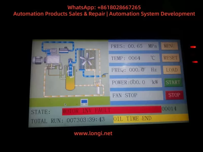
(1) On the Main Control Panel (HMI)
The compressor controller repeatedly shows the following message:
STATE: MOTOR INV FAULT
CODE: 00014
Multiple entries appear in the fault history list (024–028), all labeled “MOTOR INV FAULT.”
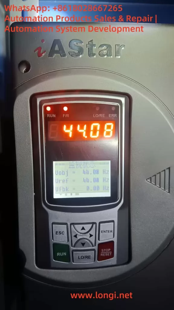
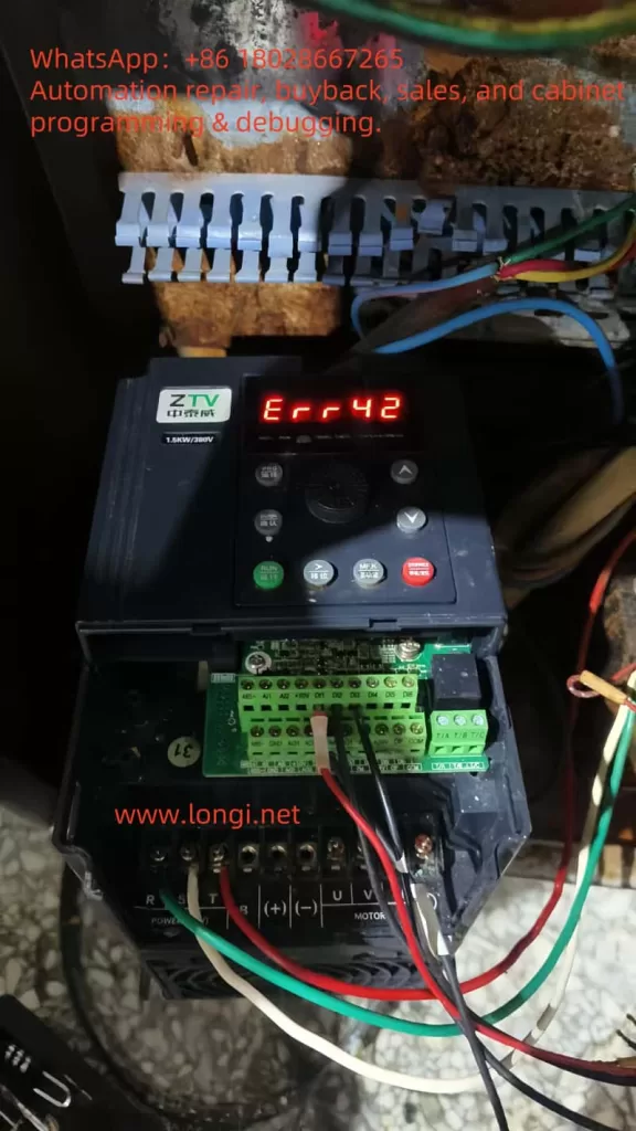
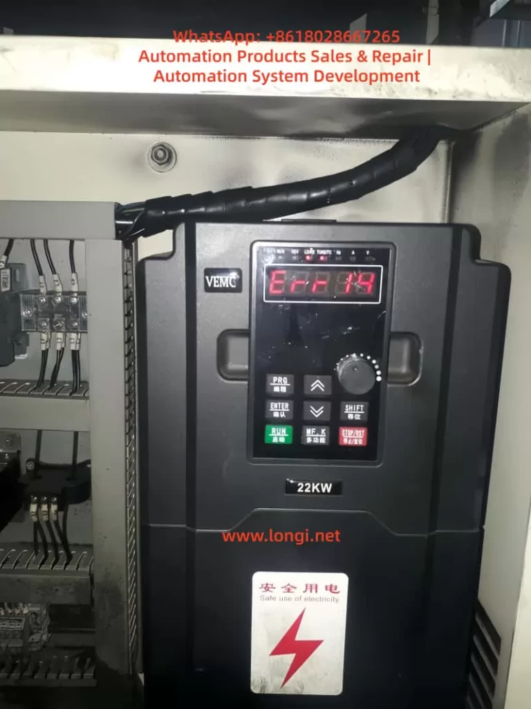
(2) On the VEMC Inverter Panel
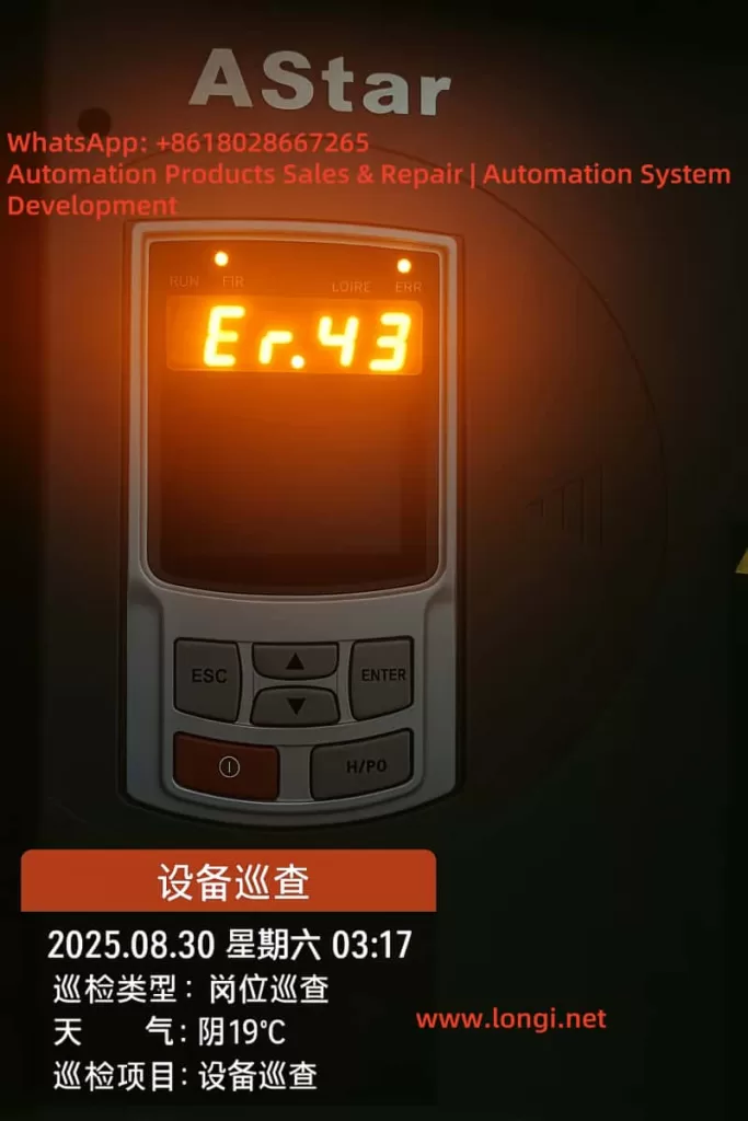
The inverter LED display reads:
Err14
The red alarm indicator is on, and the motor cannot start.
Once the contactor closes, the inverter trips immediately.
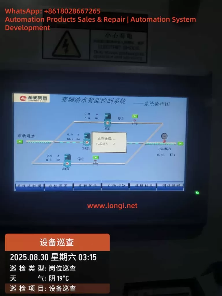
(3) PLC and System Reaction
The PLC detects the inverter fault signal and sends a stop command to the entire compressor.
Frequency display freezes at 0.0 Hz, power output shows 0.0 kW, and total run time stops accumulating.
3. Understanding the “Err14” Code — Module Overheat Fault
According to VEMC documentation:
Err14 = Module Overheat Fault (IGBT Overtemperature)
The inverter continuously monitors the IGBT module temperature via an NTC thermistor attached to the power module.
This analog signal is converted to a voltage and fed to the control CPU through an A/D converter.
- Normal temperature range: 25 °C – 75 °C
- Warning level: ~85 °C
- Trip threshold: ~95 °C
If the module temperature exceeds the limit or the temperature signal becomes abnormal (open circuit, short circuit, or unrealistic value), the inverter will immediately shut down to protect the IGBT module. The control CPU disables PWM output and reports Err14.
4. Common Root Causes of Err14
Based on maintenance experience and field diagnostics, there are five main categories of causes for Err14:
| Category | Cause | Description |
|---|---|---|
| 🌀 Cooling failure | Fan blocked or not running | Dust, oil mist, or worn bearings stop the fan, reducing heat dissipation efficiency. |
| 🌡️ Ambient overheating | Poor cabinet ventilation | When internal cabinet temperature exceeds 45 °C, the module’s junction temperature rises quickly. |
| 🔌 NTC thermistor fault | Broken, oxidized, or loose sensor | The temperature signal becomes unstable or reads as “overheated” even at normal temperature. |
| ⚡ IGBT module damage | Aging or partial short circuit | Localized overheating triggers overtemperature alarm even under light load. |
| 🧭 Control board error | Faulty sampling or amplifier circuit | A/D converter malfunction misreads temperature as extreme value, causing false alarm. |
5. Step-by-Step Diagnostic Procedure
Step 1 – Inspect the Cooling Fan and Air Duct
- Power on the inverter and check whether the internal cooling fan starts automatically.
- If the fan does not spin, measure the voltage at the fan terminals (usually DC 12 V or DC 24 V).
- Voltage present but fan not spinning → fan motor failure.
- No voltage → main control board output failure.
- Clean the air duct, dust filter, and heat-sink fins thoroughly.
Step 2 – Check Cabinet Temperature
- Use an infrared thermometer to measure temperature inside the control cabinet.
- If it exceeds 45 °C, install additional exhaust fans or ventilation openings.
- Avoid placing the cabinet near heat sources (e.g., compressor discharge pipe).
Step 3 – Test the NTC Thermistor
- Power off and wait at least 10 minutes for discharge.
- Remove the drive or power board.
- Measure resistance between NTC terminals (typically around 10 kΩ at 25 °C).
- Heat the sensor slightly with a hot-air gun — the resistance should decrease with rising temperature.
- If resistance is fixed or open circuit → replace the thermistor.
Step 4 – Check the IGBT Power Module
- Use a multimeter diode-test function to check each phase (U, V, W) to positive/negative bus.
- Any shorted or low-resistance reading (< 0.3 Ω) indicates IGBT damage.
- Verify that the power module is tightly clamped to the heat sink.
- Reapply high-quality thermal grease (e.g., Dow Corning 340) if dried or cracked.
Step 5 – Check the Control Board Temperature Circuit
If all above components are normal but Err14 remains:
- Inspect connector pins (often CN6 or CN8) for oxidation or loose contact.
- Use an oscilloscope to observe temperature signal voltage (should decrease gradually as temperature rises).
- Constant 0 V or 5 V output → indicates A/D converter or amplifier failure.
- Replace the entire driver/control board if signal circuit is defective.
6. Case Study — Actual Field Repair of a VGS30A Compressor
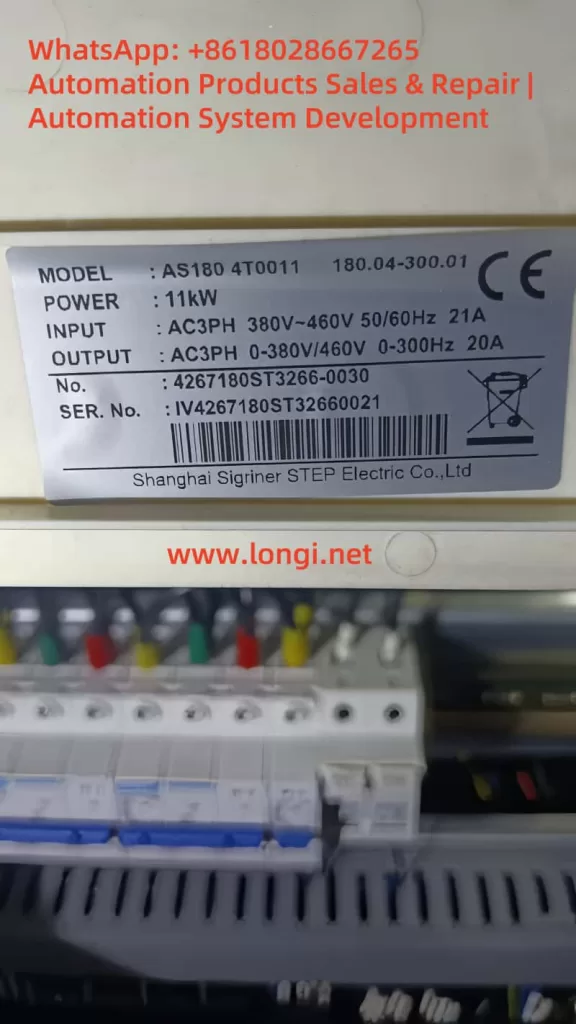
Equipment details:
- Model: Chmairss VGS30A
- Inverter: VEMC 22 kW
- Total runtime: 7 303 hours
- Ambient temperature: ~38 °C
- Fault: Err14 appears within seconds after startup; fan not rotating
Inspection and Findings
| Component | Result | Action Taken |
|---|---|---|
| Cooling fan power | 24 V output normal | Fan motor seized → replaced |
| Air duct | Heavy dust accumulation | Cleaned thoroughly |
| Thermistor | 9.7 kΩ at 25 °C | OK |
| IGBT module | All phases normal | OK |
| Thermal grease | Completely dried | Reapplied new grease |
| Control board | No oxidation or damage | OK |
After cleaning and replacing the fan, the inverter started normally.
After 30 minutes of continuous operation, module temperature stabilized at 58 °C, confirming successful repair.
7. Electrical and Thermal Theory Behind Err14
(1) Power Loss and Junction Temperature
The IGBT’s heat generation consists of conduction and switching losses:
[
P_{loss} = V_{CE} \times I_C + \tfrac{1}{2}V_{CE} I_C f_{sw} (t_{on}+t_{off})
]
If heat cannot be transferred efficiently to the heat sink, junction temperature (Tj) rises sharply, increasing conduction loss — a positive feedback that can lead to thermal runaway and module destruction.
(2) Importance of Thermal Interface
The thermal resistance (Rθjc) between IGBT and heat sink determines how quickly heat is removed.
Dried or aged thermal compound increases resistance several times, leading to localized hot spots even when load current is normal.
(3) Protection Logic Inside VEMC Drive
The inverter CPU continuously samples the temperature signal:
- Below 0.45 V (≈ 95 °C): trigger Err14 and shut down PWM output.
- Above 0.55 V (≈ 85 °C): allow reset condition.
- Open circuit: immediate fault lockout, manual reset required.
8. Preventive Maintenance Recommendations
| Task | Frequency | Recommended Action |
|---|---|---|
| Clean cooling fan and duct | Every 3 months | Use compressed air to remove dust and oil residue. |
| Replace thermal grease | Every 12 months | Apply fresh silicone-based compound between IGBT and heat sink. |
| Check ambient temperature | Continuous | Ensure cabinet stays below 40 °C. |
| Tighten wiring terminals | Every 6 months | Prevent loose or oxidized connections. |
| Record temperature log | Each service | Document operating temperature trend. |
| Inspect power module | Upon abnormal fault | Use thermal camera to detect uneven heating. |
Regular maintenance can extend inverter lifetime by 30–50 %, reduce downtime, and prevent expensive module failures.
9. Temporary Reset for Diagnostic Verification
If you suspect a false alarm:
- Power off and wait at least 10 minutes for cooling.
- Power on and press STOP/RESET.
- If Err14 reappears immediately → likely sensor or circuit fault.
- If it occurs after several minutes of operation → genuine overheating issue.
10. Troubleshooting Flow (Text Version)
Err14 Detected →
   ↓
Check Cooling Fan Running?
   ├─ No → Measure fan supply → replace fan if needed
   └─ Yes →
         ↓
Is Ambient Temperature >45°C?
         ├─ Yes → Improve ventilation
         └─ No →
               ↓
Measure NTC Thermistor Resistance
               ├─ Abnormal → Replace NTC
               └─ Normal →
                     ↓
Inspect IGBT Module & Thermal Grease
                     ├─ Abnormal → Reapply grease / replace module
                     └─ Normal →
                           ↓
Replace Driver Board (temperature circuit failure)
11. Practical Notes and Safety Reminders
- Always discharge DC bus capacitors before touching power terminals (wait >10 minutes).
- When replacing thermal grease, ensure no air gaps between module and heat sink.
- If replacing the IGBT module, apply torque evenly and use original insulation pads.
- Keep cabinet filters clean and avoid placing the compressor near exhaust heat or walls.
- Use infrared thermometer to monitor heat sink temperature during first startup after repair.
12. Lessons Learned
This case of the Chmairss VGS30A compressor with VEMC inverter Err14 demonstrates the critical role of thermal management in power electronics.
Although the message “Module Overheat” seems simple, it reflects a complex interaction between cooling airflow, thermal interface condition, and signal detection circuits.
Field statistics show:
- About 70 % of Err14 faults are resolved by cleaning the cooling path, replacing fans, or re-greasing the module.
- The remaining 30 % involve circuit faults or component failures (NTC or driver board).
Understanding these mechanisms allows engineers to diagnose quickly, repair efficiently, and reduce costly downtime.
13. Conclusion
The Err14 (Module Overheat) fault is not merely an alarm — it is the inverter’s self-protection mechanism preventing irreversible IGBT damage.
Proper analysis requires both electrical and thermal reasoning.
By following the structured diagnostic steps in this guide — inspecting the fan, air duct, thermistor, power module, and control board — maintenance engineers can isolate the root cause systematically.
Regular preventive maintenance, good ventilation, and periodic internal cleaning are the best strategies to ensure long-term reliability of VEMC inverters in air compressor applications.