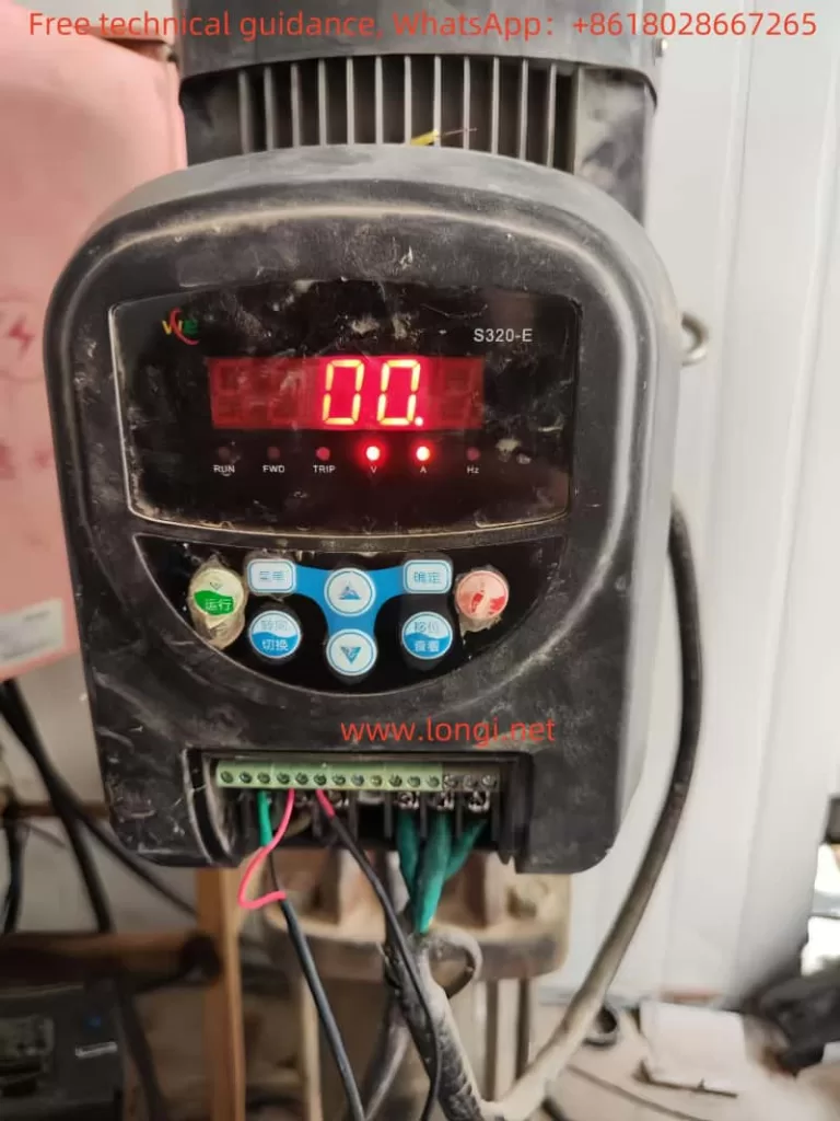
I. Introduction to the Operation Panel Functions and Parameter Settings
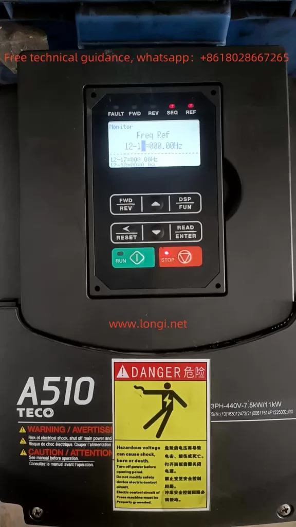
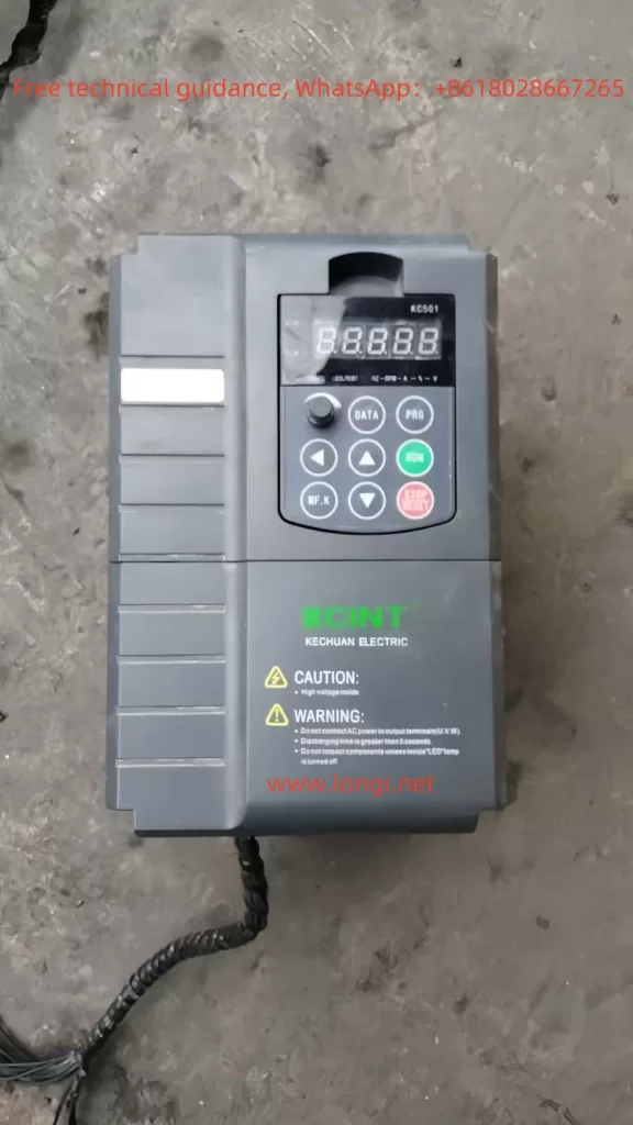
The operation panel of the Goodbell G500/G600 series frequency converter serves as the primary interface for users to control and monitor the converter. The operation panel features multiple functional buttons and a digital display, enabling users to easily perform various operations such as setting parameters, monitoring the operating status, and controlling the start and stop of the converter.
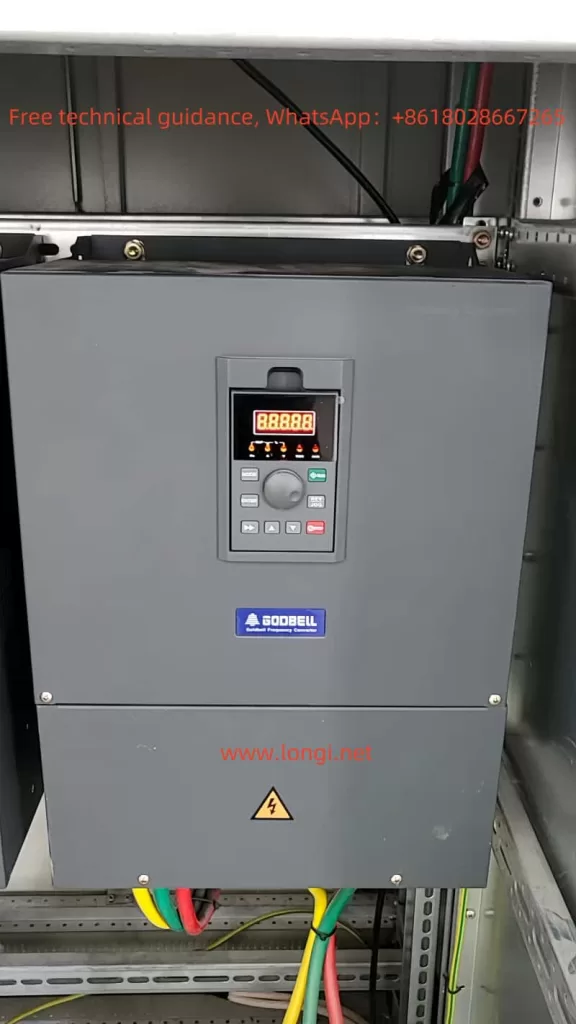
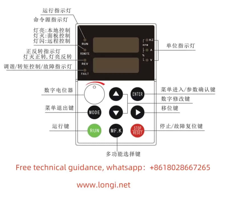
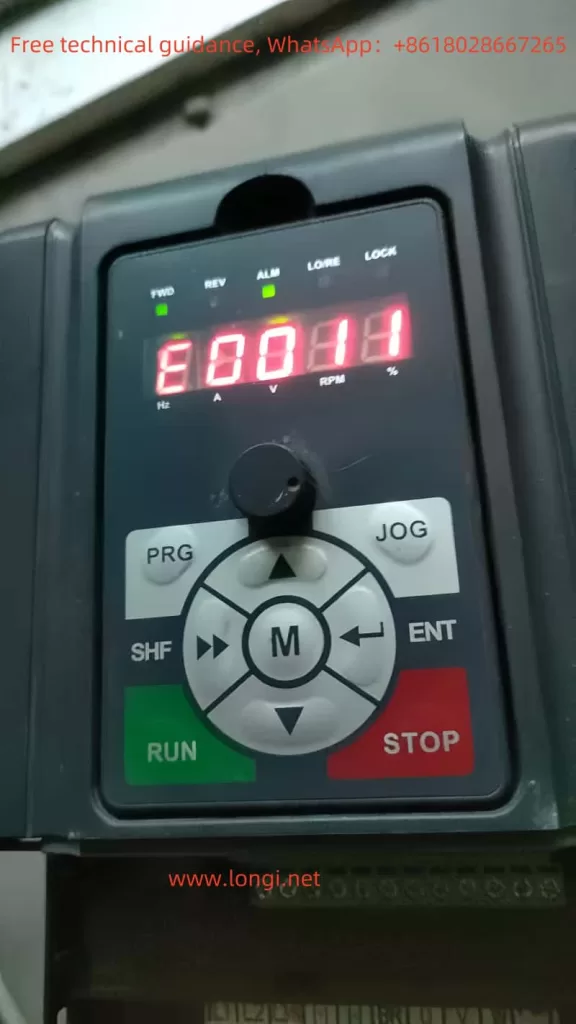
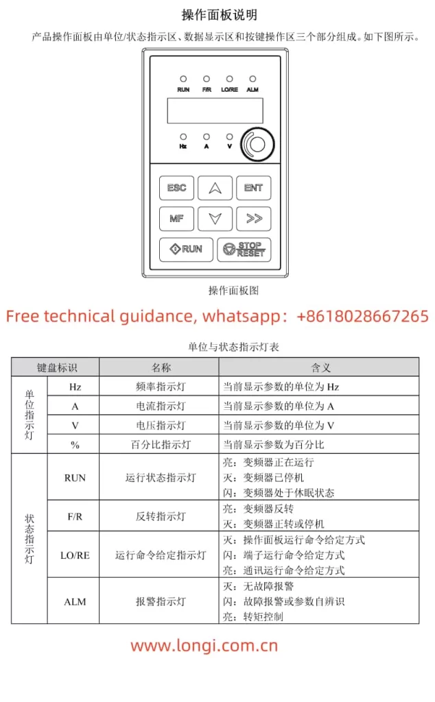
1. Introduction to Operation Panel Functions
- RUN Indicator: When the light is off, the converter is stopped. When the light is on, the converter is running.
- LOCAL/REMOT Indicator: Indicates the operation mode of the converter. Off indicates keyboard operation, on indicates terminal operation, and flashing indicates remote operation (via communication control).
- FWD/REV Indicator: Indicates the rotation direction of the motor. The light is on when rotating forwards.
- TUNE/TC Indicator: Indicates torque control mode when lit, tuning mode when flashing slowly, and fault status when flashing quickly.
- Digital Display: A 5-digit LED display that shows set frequency, output frequency, various monitoring data, and alarm codes.
- Keyboard Buttons: Include buttons for programming, entering, increasing/decreasing values, shifting, running, stopping/resetting, and multi-function selection.
2. Setting and Removing Passwords
- Setting Password: To set a password, modify parameter PP-00 to a non-zero value. Once set, users must enter the correct password to access the parameter menu.
- Removing Password: To remove the password protection, enter the password, then set PP-00 to 0.
3. Setting Parameter Lock
- Parameter Lock: To lock parameters, modify parameter PP-04 to “1” for the parameters you wish to lock. This prevents unauthorized modification of critical settings.
4. Restoring Parameter Initialization Settings
- Restoring Defaults: To restore the factory default settings (excluding motor parameters), set parameter PP-01 to “01”. To restore user-backed up parameters, set PP-01 to “501”.
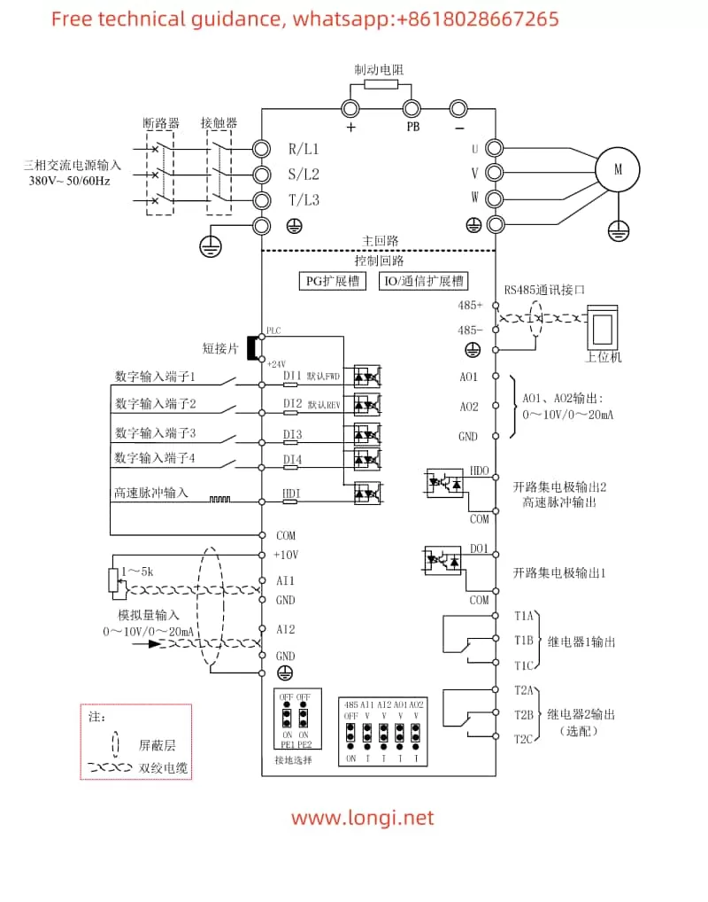
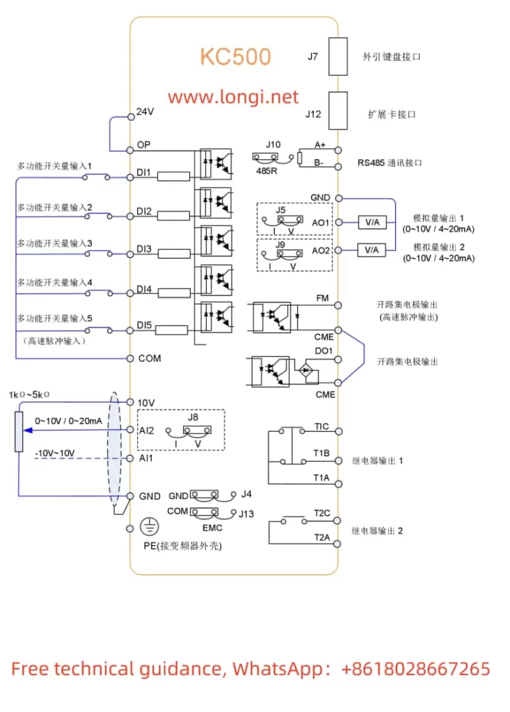
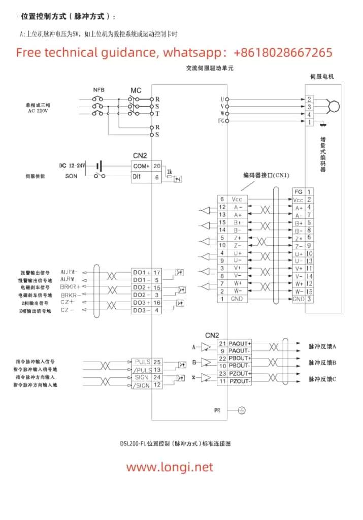
II. Terminal Connections for Forward/Reverse Start and External Potentiometer Speed Adjustment
1. Forward/Reverse Start
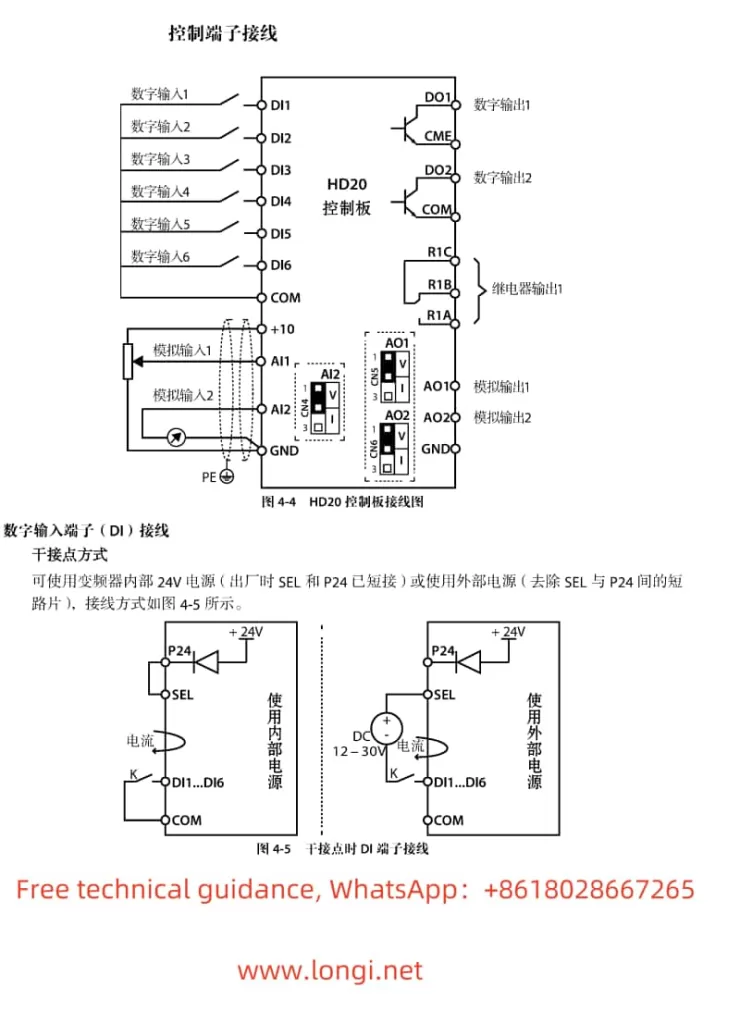
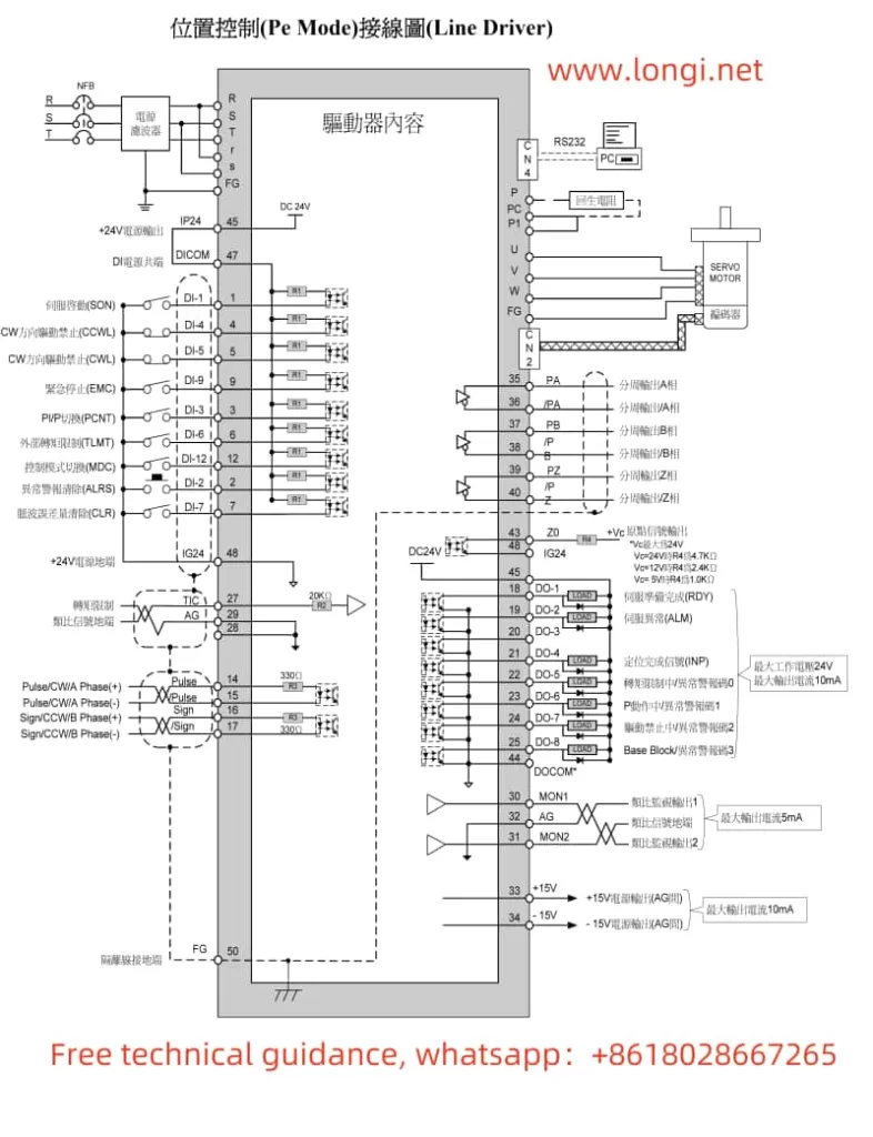
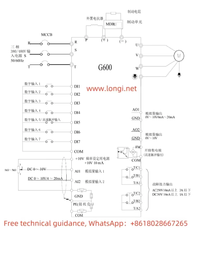
To achieve forward/reverse start control of the motor using the converter, you need to connect the appropriate terminals on the converter. Specifically:
- Forward Start: Connect the control signal to the DI1 terminal (set P4-00 to “1” for forward run).
- Reverse Start: Connect the control signal to the DI2 terminal (set P4-01 to “2” for reverse run).
2. External Potentiometer Speed Adjustment
To adjust the motor speed using an external potentiometer, connect the potentiometer’s output to the AI1, AI2, or AI3 terminal (depending on the setting of the frequency source in parameter P0-03). Ensure that the potentiometer’s output range matches the input range configured in the converter.
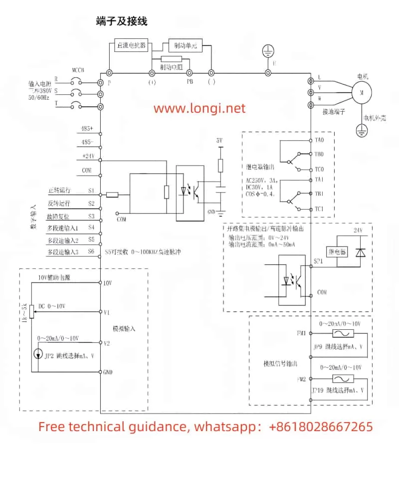
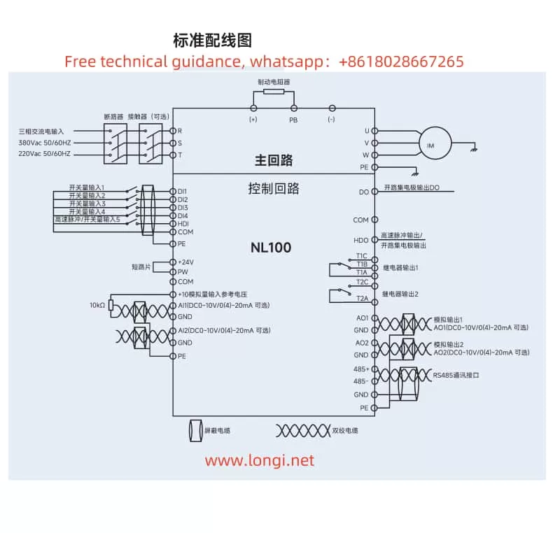
Wiring Instructions
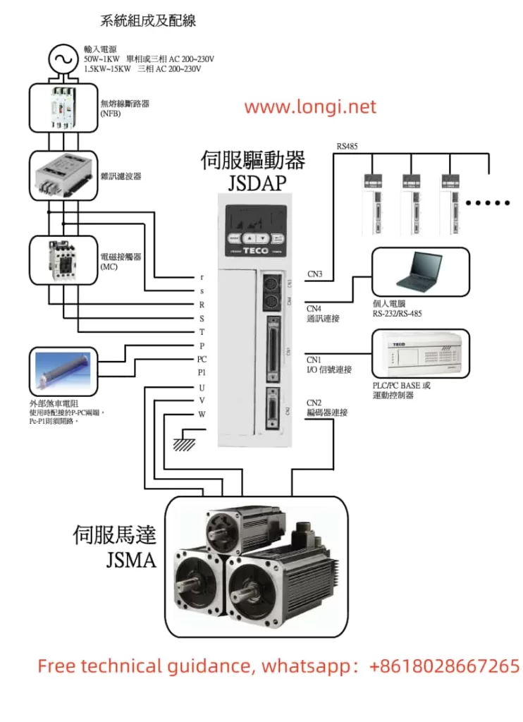
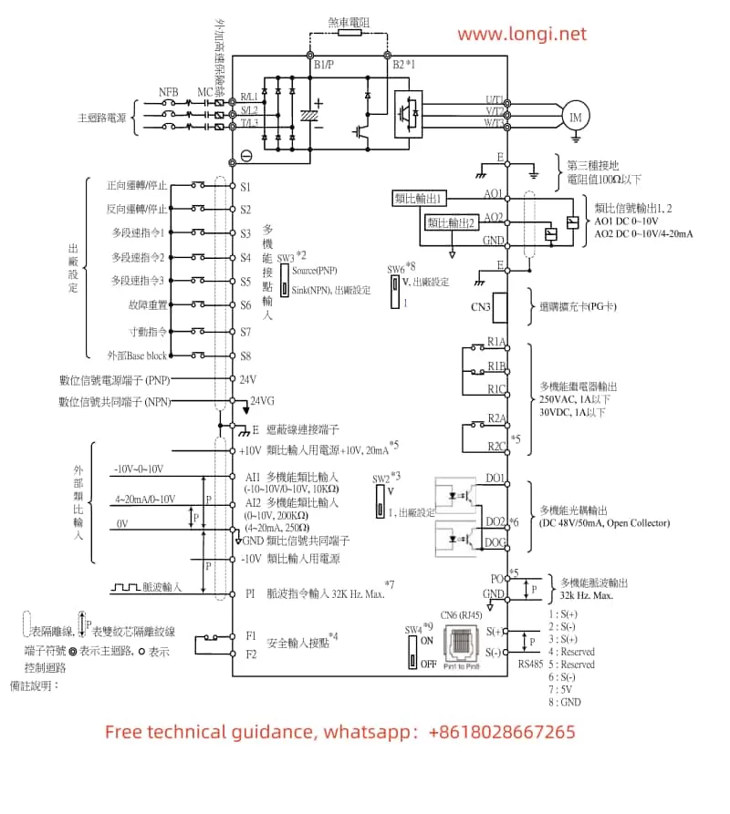
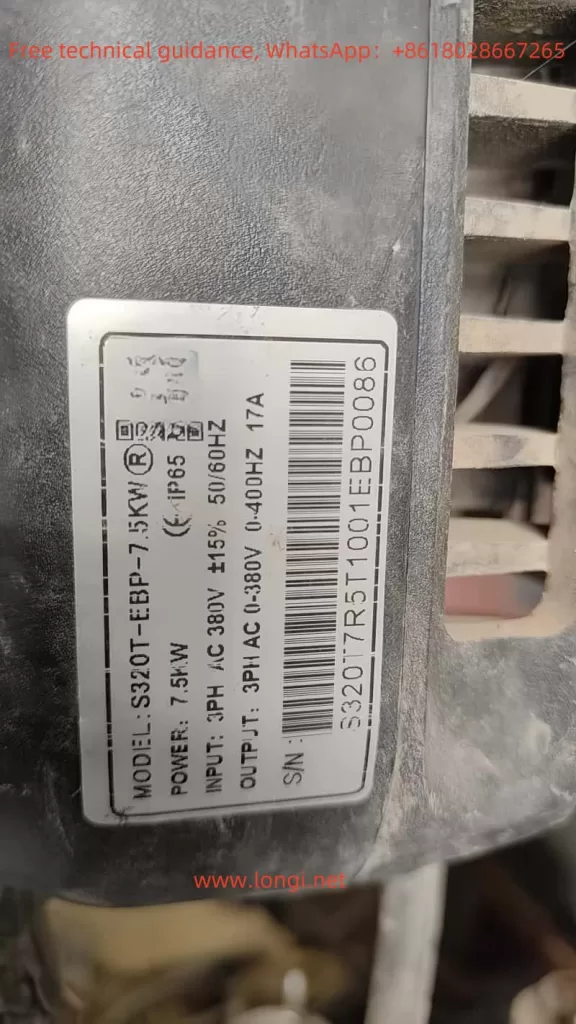
- Power Supply Connections: Ensure proper connection to the R, S, T terminals for three-phase power supply, or L1, L2 for single-phase supply.
- Motor Connections: Connect the motor’s U, V, W terminals to the corresponding terminals on the converter.
- Control Signal Connections:
- For forward/reverse control, connect the control signals to DI1 and DI2 terminals as described above.
- For speed adjustment using an external potentiometer, connect the potentiometer’s output to AI1, AI2, or AI3, and configure the relevant parameters accordingly.
- Grounding: Ensure reliable grounding of the PE terminal to prevent electrical hazards.
By following these guidelines and the detailed instructions in the user manual, users can effectively operate and configure the Goodbell G500/G600 series frequency converter to meet their specific application requirements.