I. Introduction to the Operation Panel Functions and Parameter Management
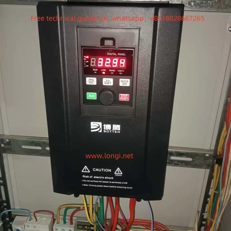
1.1 Introduction to the Operation Panel Functions
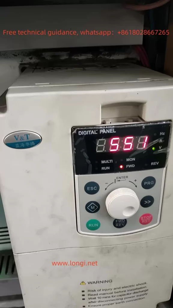
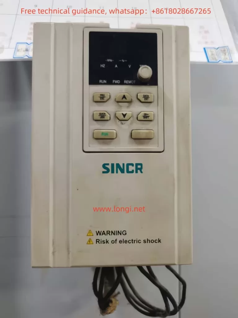
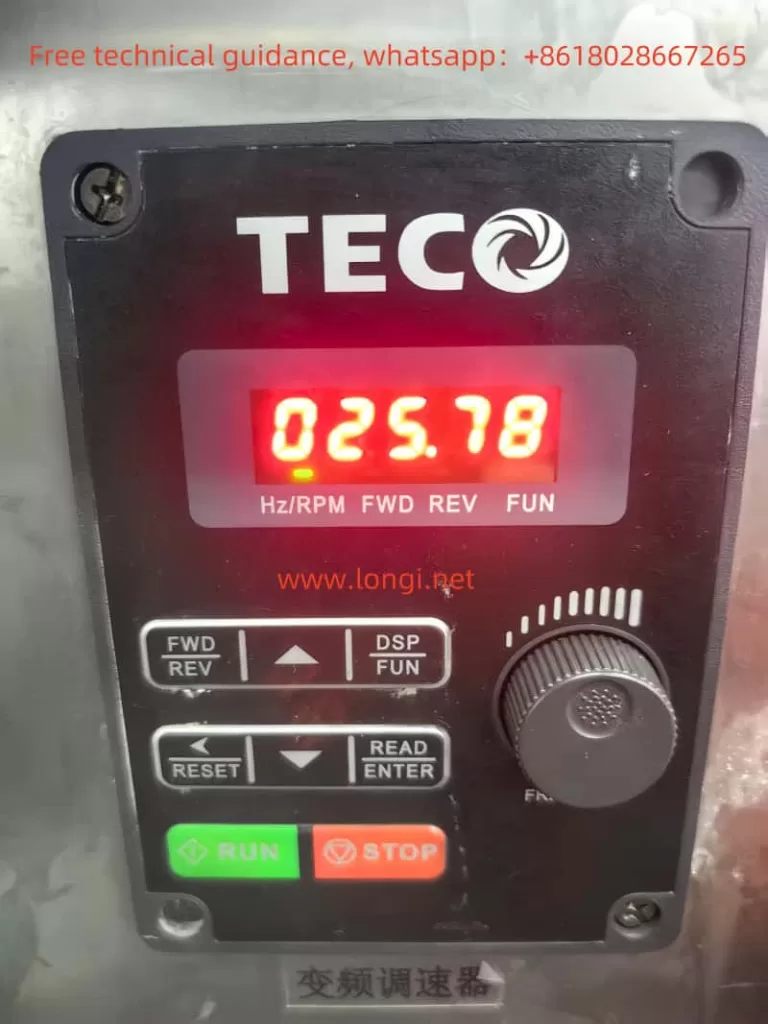
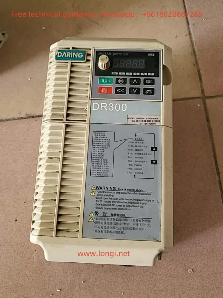
The DARING Inverter DR300A features a simple and intuitive operation panel with powerful functions. The panel is equipped with an LED display that shows the inverter’s working status, parameter settings, and fault information. The main function keys include the Run key, Stop/Reset key, Confirm key, Cancel key, Increment/Decrement key, Shift key, and Multi-function key.
- Run Key: Press this key to start the inverter.
- Stop/Reset Key: Press this key to stop the inverter during operation or to reset faults.
- Confirm Key: Used to confirm parameter settings or function selections.
- Cancel Key: Used to cancel the current operation or return to the previous menu.
- Increment/Decrement Key: Used to adjust parameter values or select menu items.
- Shift Key: Used to switch display contents or adjust the decimal point position of parameter values.
- Multi-function Key: Through settings, it can realize functions such as jog operation, positive/negative input switching, function code display switching, etc.
1.2 Copying Parameters to Another Inverter
To quickly copy parameters, the DR300A inverter provides parameter upload and download functions. The specific operation steps are as follows:
- Parameter Upload: Upload the parameters from the source inverter to the operation panel. First, ensure that the source inverter is properly connected to the operation panel. Enter the parameter copy mode, select the “Parameter Upload” function, and follow the prompts to complete the upload.
- Parameter Download: Download the parameters from the operation panel to the target inverter. Connect the target inverter to the operation panel, enter the parameter copy mode, select the “Parameter Download (with Motor Parameters)” function, and follow the prompts to complete the download.
1.3 Restoring Factory Default Settings
When it is necessary to restore the inverter parameters to their factory default values, follow these steps:
- Enter the parameter settings menu.
- Locate the “Restore Factory Defaults” function code (F0.28).
- Use the Increment/Decrement keys to select “Parameter Recovery Mode 1” or “Parameter Recovery Mode 2” (depending on whether to retain analog input/output offset parameters).
- Press the Confirm key to execute the restoration.
1.4 Setting Parameter Access Restrictions
To prevent misoperations or unauthorized access to inverter parameters, the DR300A provides a parameter protection function. By setting function code F0.01, you can choose the parameter modification permissions and initialization levels:
- 0: Both keyboard and communication port can modify parameters.
- 1: Only the keyboard can modify parameters.
- 2: Only the communication port can modify parameters.
- 3: Neither the keyboard nor the communication port can modify parameters.
Select the appropriate parameter protection level based on actual needs to ensure the security and stability of the inverter parameters.
II. External Terminal Control and Speed Regulation
2.1 External Terminal Forward/Reverse Control
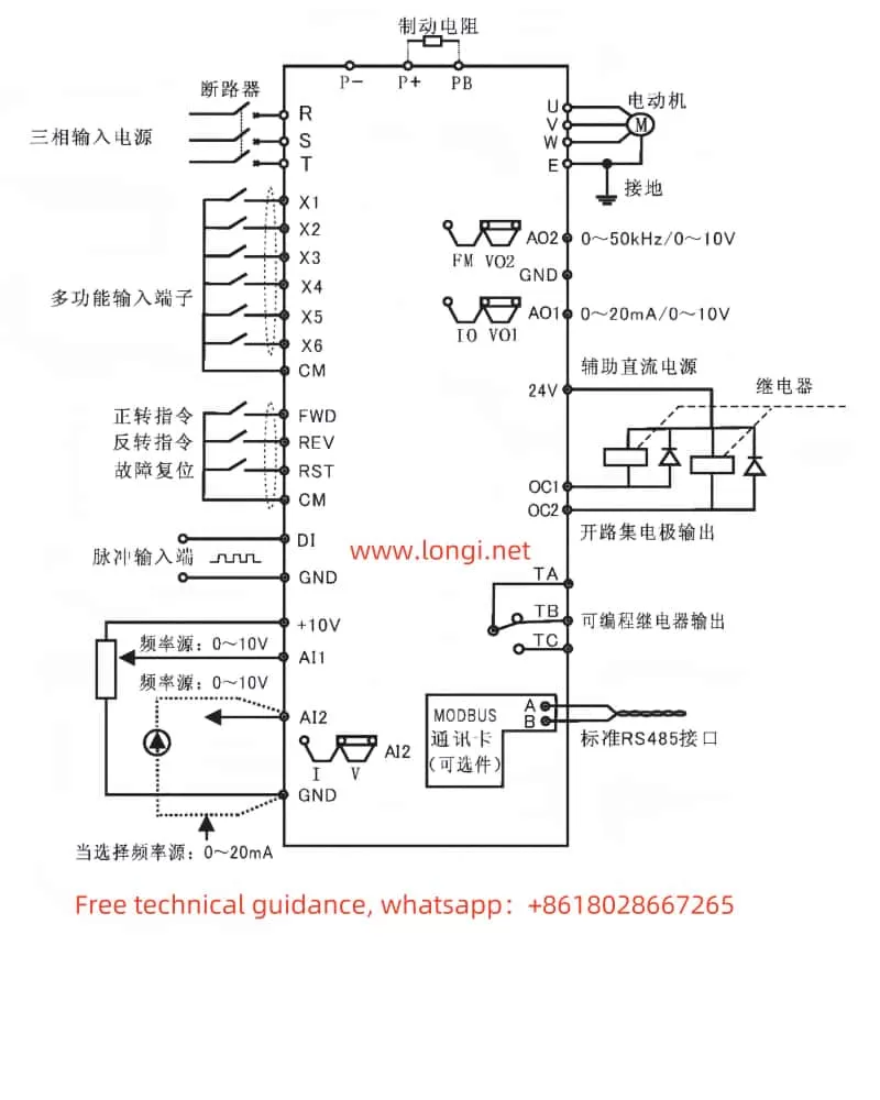
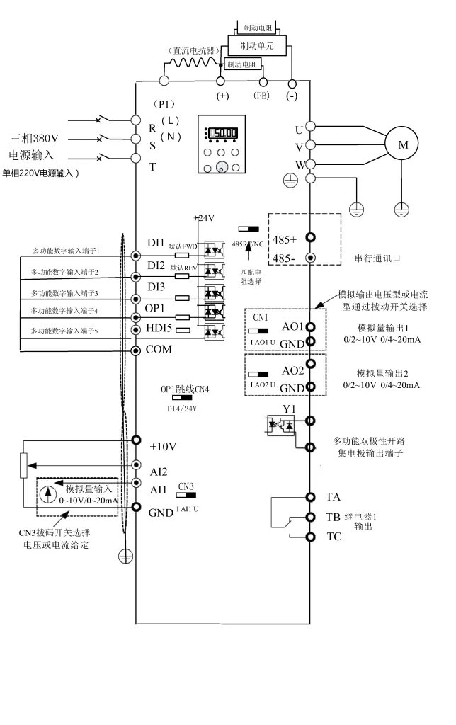
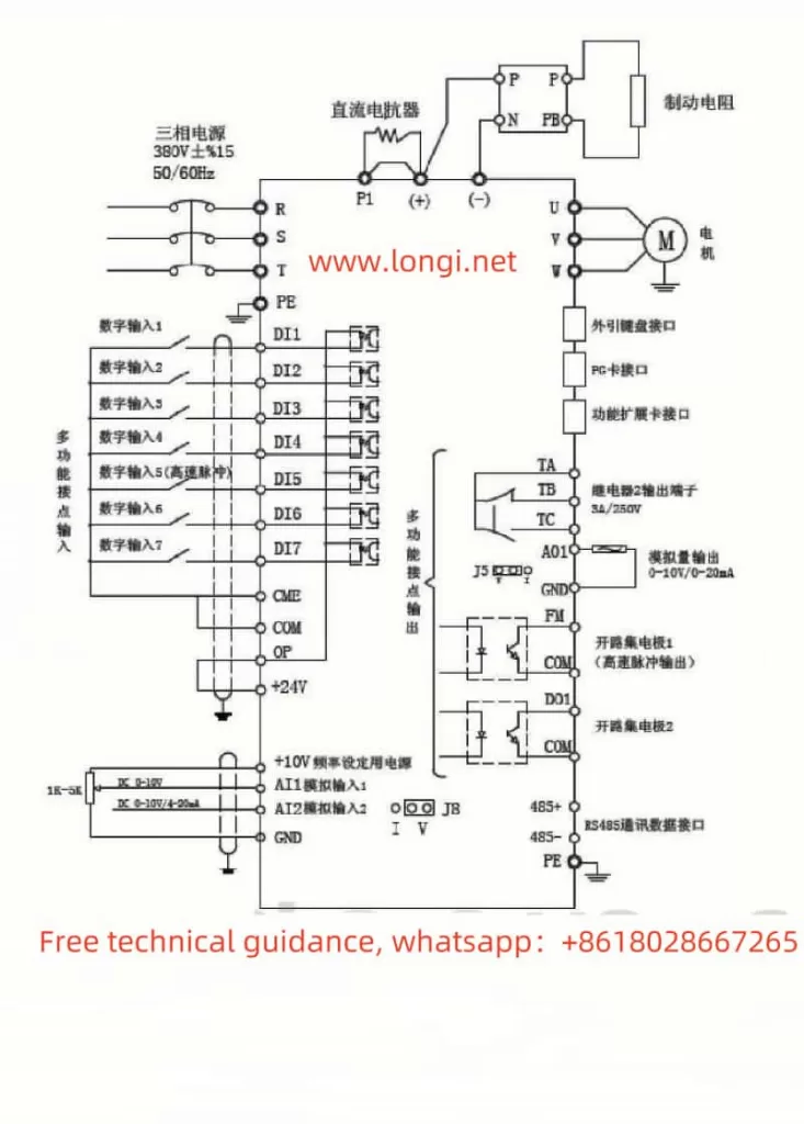
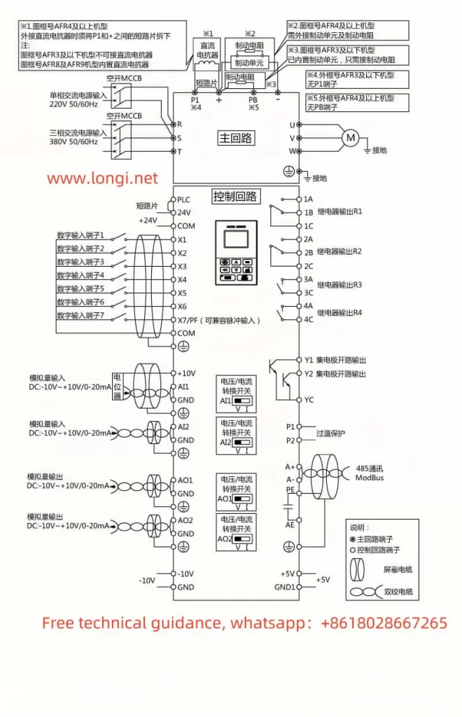
The DR300A inverter supports forward/reverse control of the motor through external terminals. The specific wiring and parameter settings are as follows:
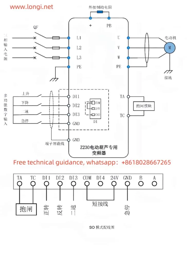
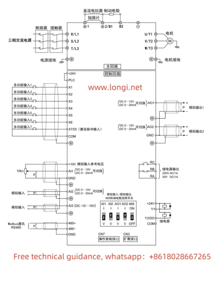
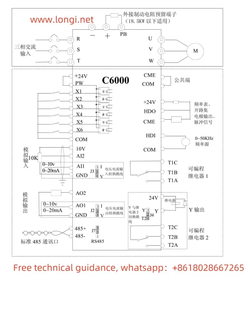
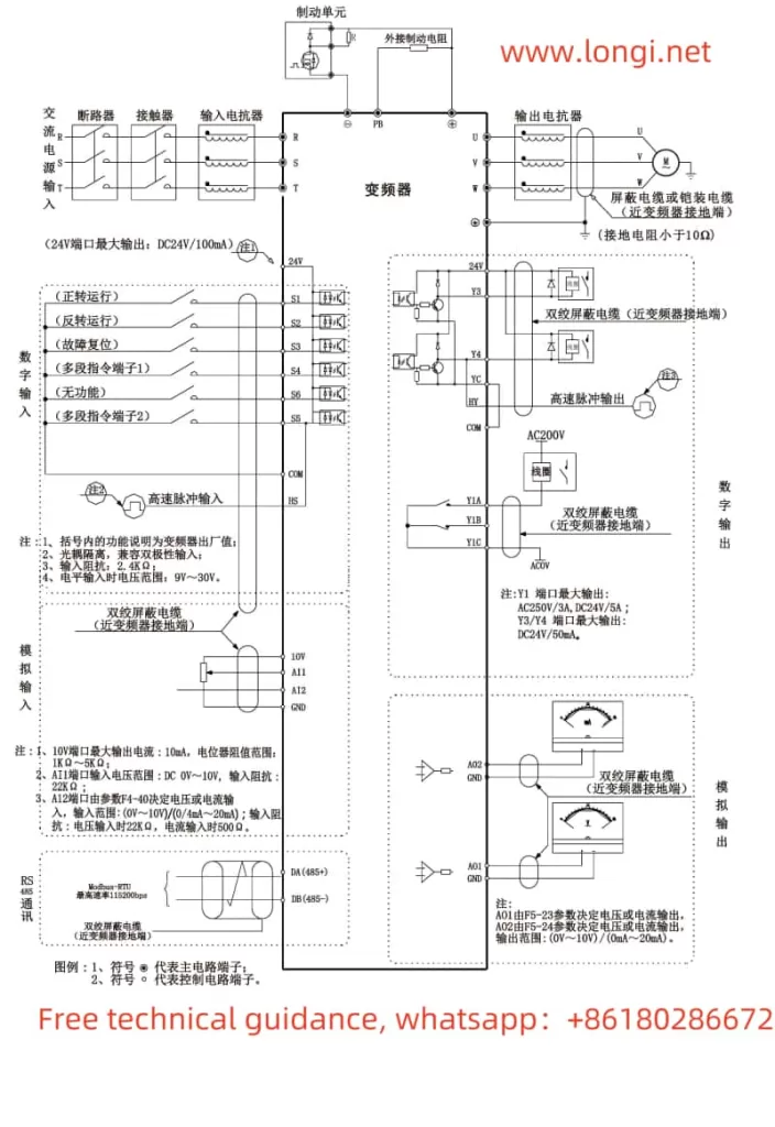
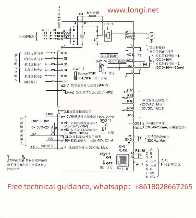
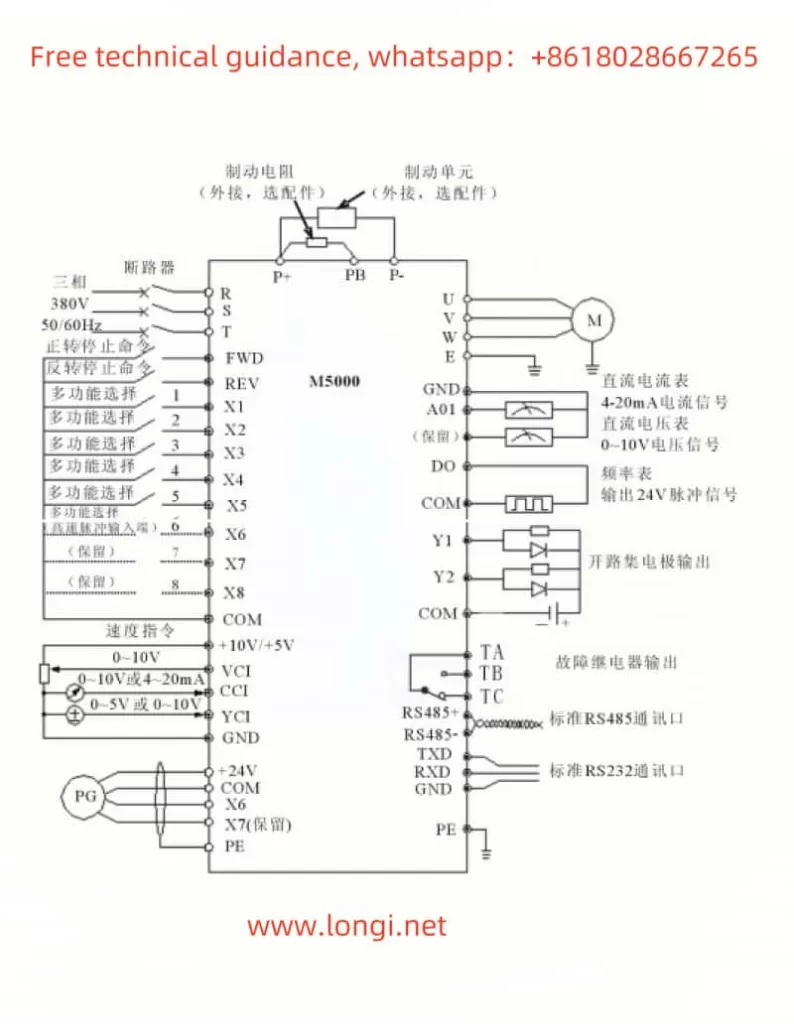
- Wiring: Connect the forward control terminal (e.g., X1) to the forward control signal source, and connect the reverse control terminal (e.g., X2) to the reverse control signal source. Ensure that the common terminal (e.g., COM) is correctly wired.
- Parameter Settings:
- Enter function code F0.05 and select “External Terminal” as the operation command source.
- Enter function code group F2 and set the functions of multifunction input terminals X1 and X2 to “Forward” and “Reverse,” respectively.
2.2 External Potentiometer Speed Regulation
The DR300A inverter also supports motor speed regulation through an external potentiometer. The specific wiring and parameter settings are as follows:
- Wiring: Connect the output terminal of the external potentiometer to the analog input terminal of the inverter (e.g., AI0), and ensure that the power supply and grounding of the potentiometer are correctly wired.
- Parameter Settings:
- Enter function code F0.08 and select “AI0 (Keyboard Potentiometer)” as the main speed setting source.
- Adjust the analog input filter time (e.g., F2.11) as needed to improve the smoothness and stability of speed regulation.
III. Fault Codes and Troubleshooting
3.1 Fault Codes and Meanings
During operation, the DARING Inverter DR300A may encounter various faults, and the corresponding fault codes will be displayed on the screen. Here are some common fault codes and their meanings:
- Err.01: Inverter unit protection. Possible causes include short circuit in the inverter output circuit, excessive motor and inverter wiring length, overheated module, etc.
- Err.02: Acceleration overcurrent. Possible causes include grounding or short circuit in the inverter output circuit, vector control without parameter tuning, too short acceleration time, etc.
- Err.03: Constant speed overcurrent. Possible causes include short circuit or leakage current in the inverter output circuit, vector control without parameter tuning, sudden load increase during operation, etc.
- Err.05: Acceleration overvoltage. Possible causes include high input voltage, external force dragging the motor during acceleration, too short acceleration time, etc.
- Err.10: Overheated module. Possible causes include high ambient temperature, blocked airflow, damaged fan, etc.
3.2 Troubleshooting Methods
For the above fault codes, the following troubleshooting methods can be adopted:
- Err.01: Check and eliminate peripheral faults, such as motor wiring and output circuits; check for blocked airflow and fan operation; if the problem persists, seek technical support.
- Err.02/Err.03: Check and eliminate peripheral faults; perform motor parameter tuning; increase acceleration/deceleration time; if the load fluctuates greatly, consider selecting an inverter with a higher power rating.
- Err.05: Adjust the input voltage to the normal range; eliminate external force dragging or install braking resistors; increase acceleration time.
- Err.10: Reduce ambient temperature; clean airflow paths; replace damaged fans or thermistors.
When troubleshooting, always follow safety operating procedures to ensure personal and equipment safety. If the fault cannot be resolved independently, promptly contact a professional technician for repair.
By thoroughly understanding the DARING Inverter DR300A manual, users can better grasp the operation panel functions, parameter management methods, external terminal control and speed regulation settings, as well as fault codes and troubleshooting methods, providing a strong guarantee for the safe and stable operation of the inverter.