
1. Introduction
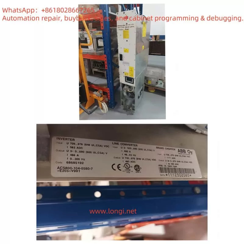
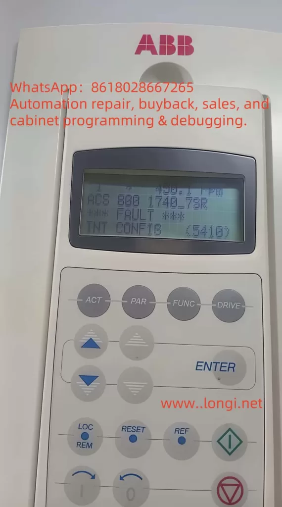
The ABB ACS800 is a high-performance inverter widely used in industrial applications, such as pump, fan, and hoist motor control systems. Its advanced features, including harmonic suppression and flexible programming capabilities, enable it to excel in demanding environments. However, like any complex electronic device, it is prone to faults. One common configuration-related fault is “FAULT INT CONFIG 5410,” which indicates a mismatch between the number of inverter modules and the system configuration.
This guide provides a detailed analysis of the fault’s meaning, causes, on-site troubleshooting steps, hardware disassembly and repair methods, and preventive measures to avoid recurrence. The content is based on official documentation, user experiences, and expert advice to ensure accuracy and practicality.
2. Fault Code Analysis
The “FAULT INT CONFIG 5410” fault indicates that the number of inverter modules in the ABB ACS800 inverter does not match the initial system configuration. The inverter module is the core component responsible for converting DC power into AC power suitable for the motor. If the actual number of modules does not align with the parameter settings, the inverter triggers this fault to protect the system.
Fault Causes
Based on official documentation and user feedback, the following are the primary causes of this fault:
- Configuration Mismatch: Configuration parameters were not updated after adding or removing inverter modules.
- Fiber Optic Connection Issues: Fiber optic communication between the APBU (Active Power Buffer Unit) and the inverter modules fails due to loose connections, dirty connectors, or damaged fiber optics.
- Derating Operation Issues: In derating mode (where some modules are disabled), unused modules were not properly removed, or configuration parameters were not updated.
3. On-Site Handling and Troubleshooting
When the inverter displays “FAULT INT CONFIG 5410,” a systematic approach should be taken for diagnosis and resolution. Below are detailed on-site handling steps:
Step 1: Check Internal Fault Information
Use the inverter’s control panel or programming tool (such as ABB’s Drive Composer or Drive Window) to access parameter 23.34 INT FAULT INFO (or 04.01 FAULTED INT INFO in some versions).
This parameter provides detailed fault information to help identify specific issues, such as which module or connection is abnormal.
Step 2: Check Fiber Optic Connections
Inspect the fiber optic connections between the APBU and the inverter modules to ensure all connections are secure and free from physical damage.
Clean the connectors using a fiber optic cleaning kit to remove any dust or dirt that may affect communication.
Ensure the fiber optics are properly inserted into the connectors to prevent looseness.
Step 3: Verify Inverter Module Configuration
Check parameter 16.10 INT CONFIG USER (or 95.03 INT CONFIG USER, depending on the version) to confirm the configured number of inverter modules.
Physically inspect the number of inverter modules inside the inverter to ensure it matches the parameter settings.
If a mismatch is found, update parameter 16.10 INT CONFIG USER to reflect the actual number of modules.
Step 4: Handle Derating Operation
If the inverter is operating in derating mode (with some modules unused), ensure the disabled inverter modules are removed from the main circuit.
Update parameter 16.10 INT CONFIG USER to input the current number of active modules.
Step 5: Reset the Inverter
After completing the above adjustments, reset the inverter to clear the fault. Reset methods include:
- Power Cycle Reset: Turn off the inverter power, wait a few minutes, and then power it on again.
- Control Panel Reset: Use the reset function on the control panel to clear the fault.
- Programming Tool Reset: Send a reset command using the programming tool.
Required Tools and Safety Precautions
Required Tools:
- Multimeter: For checking electrical connections.
- Fiber optic cleaning kit: For cleaning fiber optic connectors.
- Programming tool: Such as Drive Composer, for accessing and modifying parameters.
Safety Precautions:
- Ensure the inverter is completely powered off and isolated from the power source before performing any checks or adjustments.
- Wear appropriate personal protective equipment (PPE), including insulating gloves and safety goggles.
- Strictly adhere to the safety guidelines in the ABB ACS800 Hardware Manual (ABB Library).
4. Hardware Inspection and Repair
If the fault persists after following the above steps, there may be a hardware issue requiring further inspection and repair.
Identifying Hardware Issues
- Visual Inspection: Check the inverter modules and fiber optic connectors for physical damage, such as burn marks, loose connections, or corrosion.
- Module Testing: If possible, test each inverter module individually to determine if any are faulty. This may require professional equipment or assistance from ABB technical support.
- Fiber Optic Testing: Use a fiber optic tester to check if the fiber optics are functioning properly and ensure unobstructed communication.
Disassembly and Repair
Disassembling an ABB ACS800 inverter is a high-risk operation and should only be performed by qualified personnel experienced in handling high-voltage equipment. Below are general disassembly and repair steps; specific operations should refer to the ABB ACS800 Hardware Manual.
Step 1: Prepare for Disassembly
- Ensure the inverter is completely powered off and isolated from the power source.
- Wear appropriate PPE, including insulating gloves and safety goggles.
Step 2: Remove the Housing
- Carefully remove the inverter’s housing to access internal components, following the guidance in the hardware manual.
Step 3: Locate the Inverter Modules
- Find the inverter modules, typically located in a modular structure within the inverter.
Step 4: Inspect and Replace Modules
- If a module is suspected to be faulty, it may need to be replaced. Safely remove the faulty module and install a new one, following the manual’s instructions.
- Ensure the replacement module is compatible with the ACS800 and properly configured.
Step 5: Reassemble and Test
- After replacing the faulty component, carefully reassemble the inverter.
- Power on and test the inverter to confirm the fault has been resolved.
Note: If unsure about hardware repairs, it is recommended to contact ABB technical support or a certified service provider. The ABB ACS800 Hardware Manual (ABB Library) provides detailed guidance on disassembly and component replacement.
5. Preventive Measures
To prevent the recurrence of the “FAULT INT CONFIG 5410” fault, the following preventive measures can be taken:
- Regular Maintenance: Regularly inspect fiber optic connections to ensure they are clean and secure.
- Configuration Updates: Promptly update parameters (such as 16.10 INT CONFIG USER) when adding or removing inverter modules.
- Personnel Training: Ensure operators and maintenance personnel are trained in inverter operation, configuration, and troubleshooting.
- Record Management: Keep detailed records of all configuration and hardware changes to facilitate quick problem identification.
- Environmental Control: Protect the inverter from harsh environmental conditions (such as dust and moisture) to maintain the integrity of fiber optics and modules.
6. Conclusion
The “FAULT INT CONFIG 5410” fault in the ABB ACS800 inverter is caused by a mismatch between the number of inverter modules and the configuration. By checking the inverter status, fiber optic connections, and updating configuration parameters, the issue can usually be resolved. If the fault persists, hardware inspection and repair may be necessary, which should be performed by professionals following the ABB ACS800 Hardware Manual.
Through the fault analysis, on-site handling steps, and preventive measures provided in this guide, users can effectively diagnose and resolve the fault to ensure reliable inverter operation. For further assistance, refer to official documentation or contact ABB technical support.
Fault Code Reference Table
| Fault Code | Name | Cause | Handling Method |
|---|---|---|---|
| 5410 | INT CONFIG | Mismatch between the number of inverter modules and initial configuration | Check inverter status (signal 04.01 FAULTED INT INFO), inspect fiber optic connections between APBU and modules; if using derating function, remove faulty modules and update parameter 95.03 INT CONFIG USER, reset the inverter. |