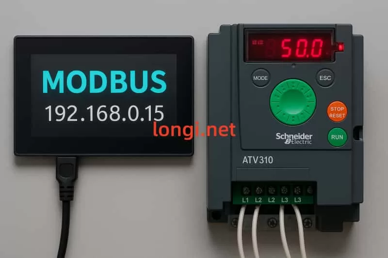
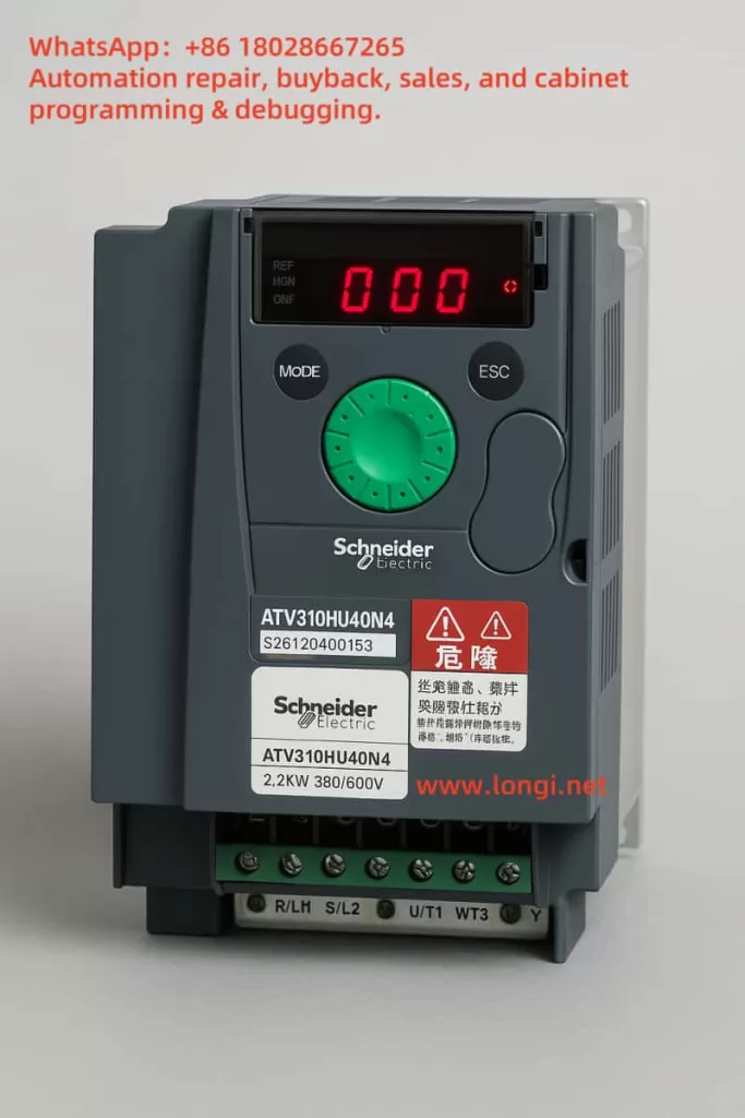
Posted on Leave a comment

ABB ACS800 Variable Frequency Drive 4280 Fault: Meaning, Solution, and Fan Running Time Reset Guide

Introduction

ABB ACS800 series variable frequency drives are core devices in industrial automation, renowned for their high performance and reliability. They are widely used in industries such as papermaking, metallurgy, mining, power, and chemical engineering. These drives precisely control motor operations, supporting applications ranging from 0.75 to 7500 horsepower. However, like any complex equipment, they may encounter faults. The 4280 fault code is a common warning signal that alerts users to the condition of the cooling fan.

The 4280 fault is directly related to the cooling fan’s lifespan. Addressing this warning promptly prevents overheating and extends the drive’s operational life. This article explores the meaning of the 4280 fault, its causes, potential risks, solutions, and detailed steps to reset the fan running time counter, offering comprehensive maintenance guidance.

Part One: Meaning of the 4280 Fault

1.1 Fault Definition

The 4280 fault code is an informational warning, typically displayed as “REPLACE FAN.” It indicates that the cooling fan’s running time has exceeded the manufacturer’s estimated lifespan threshold. This warning does not imply complete fan failure but suggests that the fan is nearing its performance limit and requires replacement to maintain effective heat dissipation.

  • Key Characteristics:
    • Type: Informational warning, does not cause immediate shutdown.
    • Code: 4280.
    • Impact: If ignored, it may lead to inadequate cooling, affecting performance.

The cooling fan is a critical component of the drive’s heat dissipation system, responsible for expelling heat generated during operation. A decline in fan performance can elevate internal temperatures, potentially triggering more severe faults.

ACS800 fan

1.2 Triggering Conditions

The 4280 fault is triggered when the fan running time counter (parameter 01.44) reaches or exceeds the preset lifespan value. Manufacturers set this threshold based on the fan’s design and typical operating conditions, generally between 20,000 and 40,000 hours, depending on the model and environment.

Part Two: Causes of the 4280 Fault

2.1 Normal Wear and Tear

As a mechanical component, the cooling fan experiences wear on parts like blades and bearings over prolonged use. The designed lifespan is measured in hours, and continuous operation accelerates this wear.

2.2 Environmental Factors

  • High Temperature: Operating in environments above 40°C forces the fan to run more frequently, hastening aging.
  • Dust and Debris: Dust accumulation on blades increases load, reducing efficiency.
  • Humidity: High humidity may cause internal corrosion, shortening the fan’s lifespan.

2.3 Operating Mode

Continuous 24/7 operation accelerates fan wear compared to intermittent use. Heavy-load applications also increase the fan’s workload.

2.4 Lack of Maintenance

Failure to regularly clean or inspect the fan can lead to dust buildup or mechanical issues, prematurely triggering the lifespan warning.

Part Three: Potential Hazards of the 4280 Fault

3.1 Device Overheating

A failing cooling fan can cause the drive’s internal temperature to rise beyond safe limits, potentially triggering temperature-related faults like 4210 ACS800 TEMP.

3.2 Performance Degradation

To prevent overheating, the drive may reduce output power (derate), impacting connected devices (e.g., motors) and lowering production efficiency.

3.3 Component Damage

Prolonged overheating can harm critical components, such as IGBT modules or control circuits, increasing repair costs.

3.4 Production Interruption

In extreme cases, overheating may cause the drive to shut down, leading to production line disruptions and economic losses.

Promptly addressing the 4280 fault is essential for maintaining device reliability and production continuity.

Part Four: Diagnosing the 4280 Fault

4.1 Check Fan Running Time

  • Steps: Use the control panel to view parameter 01.44 and confirm the fan’s actual running time.
  • Reference Values: Fan lifespan is typically 20,000 to 40,000 hours, as specified in the device manual.

4.2 Physical Inspection

  • Steps: Check if the fan operates normally, looking for abnormal noise, vibration, or overheating signs.
  • Tools: Use a stethoscope or infrared thermometer to assess fan performance.

4.3 View Fault History

  • Steps: Access the control panel’s fault history to confirm the frequency and conditions of the 4280 warning.
  • Purpose: Determine if it’s a long-term issue or caused by environmental factors.

Part Five: Resolving the 4280 Fault

5.1 Replace Cooling Fan

  1. Safety Preparations:
    • Disconnect the drive’s power and follow lockout-tagout procedures.
    • Wear insulated gloves and safety goggles.
  2. Locate the Fan:
    • The cooling fan is typically on the side or top of the drive; refer to the manual for the exact location.
  3. Remove the Old Fan:
    • Remove securing screws or clips and carefully extract the fan, avoiding damage to connecting wires.
  4. Install the New Fan:
    • Use a fan matching the original equipment’s model and specifications.
    • Secure the new fan and connect the cables.
  5. Verify Operation:
    • Restore power and ensure the fan runs normally without abnormal noises.

5.2 Reset Fan Running Time Counter

  1. Access Control Panel:
    • Stop the drive and enter the parameter setting interface.
  2. Locate Parameter 01.44:
    • Navigate to parameter group 01 and find the fan running time counter.
  3. Reset Counter:
    • Set parameter 01.44 to 0 and save the setting.
  4. Verify:
    • Recheck parameter 01.44 to confirm it displays 0 and the warning is cleared.

Note: If the parameter is locked or inaccessible, use ABB’s Drive Composer software via a PC.

Part Six: Detailed Steps for Resetting Fan Running Time

  1. Access Control Panel:
    • With the drive stopped, use the control panel to enter the main menu.
  2. Navigate to Parameter Group 01:
    • Use the up/down arrow keys to locate parameter 01.44 (fan running time counter).
  3. Modify Value:
    • Press “EDIT” or “ENTER” and input 0.
  4. Save Settings:
    • Press “SAVE” or the confirm key to apply the parameter.
  5. Verify Reset:
    • Recheck parameter 01.44 to confirm the value is 0.

Note: Control panel operations may vary by model or firmware version; consult the device manual. For permission issues, contact technical support.

Part Seven: Preventive Measures

7.1 Regular Maintenance

  • Clean the fan and heat sink every 6-12 months using compressed air or a soft brush to remove dust.
  • Check the fan’s operating status for abnormalities.

7.2 Monitor Running Time

  • Regularly check parameter 01.44 to track fan running time.
  • Plan replacement when nearing the lifespan threshold (e.g., 30,000 hours).

7.3 Improve Environmental Conditions

  • Install the drive in a well-ventilated area with temperatures between 0-40°C.
  • Use air filters to minimize dust ingress.

7.4 Train Operators

  • Ensure operators are trained in maintenance procedures to quickly identify and address warnings.

Part Eight: Discussion and Limitations

The 4280 fault solution is straightforward but requires familiarity with control panel operations. If parameter 01.44 is inaccessible due to firmware or permission issues, professional software or technical support may be needed. Fan lifespan varies by environment; high-temperature or dusty conditions necessitate more frequent maintenance.

In some cases, the warning may appear frequently despite a functional fan. Adjusting the maintenance schedule may help, but the cooling system’s overall safety must be ensured.

Part Nine: Conclusion

The 4280 fault in ABB ACS800 variable frequency drives signals that the cooling fan has reached its lifespan. Replacing the fan and resetting parameter 01.44 effectively resolves the issue. Regular maintenance, running time monitoring, and environmental optimization can minimize faults and extend equipment life. The cooling fan is vital to the drive’s heat dissipation system, and maintaining its condition is crucial for production efficiency and reliability.

Appendix: 4280 Fault Related Information

Fault CodeDescriptionRelated ParameterType
4280REPLACE FAN: Fan lifespan expired01.44Warning

Appendix: Fan Lifespan Reference Values

Device TypeTypical Lifespan (hours)Parameter
ACS800 Standard20,000–40,00001.44 (counter)
Posted on Leave a comment

Meaning and Solutions for the “DC BUS lim” Warning in ABB ACS800 Series Frequency Converters

Introduction

The ABB ACS800 series of frequency converters are core components in the industrial automation sector, widely used in industries such as papermaking, metals, mining, power, and chemicals. With a power range spanning from 0.75 hp to 7500 hp, they are adaptable to various complex application scenarios. However, during operation, the frequency converter may display warning or fault codes, among which “DC BUS lim” (code 3211) is a common informational alert. This warning indicates an abnormal DC bus voltage, potentially affecting device performance and even system safety. Understanding the meaning, causes, and solutions for the “DC BUS lim” warning is crucial for ensuring stable device operation and extending its service life.

This article will delve into the definition, triggering conditions, diagnostic steps, solutions, and preventive measures for the “DC BUS lim” warning, providing comprehensive guidance for users.

Part 1: Understanding the “DC BUS lim” Warning

1.1 Definition of the Warning

The “DC BUS lim” warning is an informational alert in the ABB ACS800 frequency converter, identified by code 3211 and associated with status bit 03.18 ALARM WORD 5 (bit 15). It indicates that the DC bus voltage in the intermediate circuit of the frequency converter has reached the supervisory limit range (either too high or too low), prompting the frequency converter to limit output torque to protect itself and connected equipment. This warning is controlled by the programmable fault function parameter 30.23 (bit 1) and is part of the protection mechanism.

DC BUS LIM

Key Characteristics:

  • Type: Informational alert (does not cause immediate device shutdown).
  • Code: 3211 (some documents may reference 7114, depending on firmware version).
  • Impact: Torque limitation may lead to reduced performance, but the device remains operational.

1.2 Triggering Conditions for the Warning

The “DC BUS lim” warning is typically triggered under the following conditions:

  • High DC Bus Voltage: Exceeds the maximum allowable value for the device (e.g., 728V for 400V series, 877V for 500V series, and 1210V for 690V series).
  • Low DC Bus Voltage: Falls below the minimum value for the device (e.g., 307V for 400V and 500V series, 425V for 690V series).

These voltage anomalies may be caused by external power supply issues or internal load characteristics.

Part 2: Common Causes of the “DC BUS lim” Warning

The following are the primary reasons for the “DC BUS lim” warning:

2.1 High Input Voltage

  • Description: The input AC power supply voltage exceeds the frequency converter’s specifications (e.g., 380–415V for 400V series, 380–500V for 500V series).
  • Impact: High input voltage directly leads to an increase in DC bus voltage, triggering the warning.
  • Example Scenario: Abnormal grid voltage or incorrect transformer configuration.

2.2 Load Regeneration Energy

  • Description: During rapid deceleration or overloading (e.g., lowering heavy loads), the motor may feed energy back into the DC bus, causing the voltage to rise.
  • Impact: If the regenerated energy is not effectively dissipated, it can push up the DC bus voltage.
  • Example Scenario: Rapid descent of a crane or sudden deceleration of a high-speed motor.

2.3 Power Supply Instability

  • Description: Power loss (e.g., single-phase failure), damaged fuses, or unstable grid conditions may cause fluctuations in the DC bus voltage.
  • Impact: Low or unstable voltage may trigger the warning.
  • Example Scenario: Aging grid infrastructure or interference caused by other equipment in the factory.

2.4 Voltage Fluctuations

  • Description: Switching operations of other equipment on the grid may cause transient voltage changes.
  • Impact: These fluctuations may cause the DC bus voltage to briefly exceed the normal range.
  • Example Scenario: Startup or shutdown of large motors.

Part 3: Diagnosing the “DC BUS lim” Warning

Accurate diagnosis is a prerequisite for resolving the warning. The following are recommended diagnostic steps:

3.1 Check Input Power Supply Voltage

  • Steps: Use a multimeter to measure the phase-to-phase voltage of the input AC power supply, ensuring it is within the device’s specifications (e.g., 380–415V for 400V series).
  • Considerations: Check for single-phase loss, damaged fuses, or loose wiring.
  • Tools: High-precision multimeter.

3.2 Monitor DC Bus Voltage

  • Steps: View the DC bus voltage through the frequency converter’s control panel or an external measuring device.
  • Reference Values:
    • 400V Series: Approximately 540V (normal operation).
    • 500V Series: Approximately 680V.
    • 690V Series: Approximately 950V.
  • Abnormal Conditions: If the voltage is significantly high (approaching or exceeding 728V, 877V, or 1210V) or low (below 307V or 425V), further investigation is required.

3.3 Review Fault History Records

  • Steps: Access the control panel, navigate to parameter group 30 (fault functions) or the fault history records, and check for other related warnings (e.g., “DC OVERVOLTAGE” or “DC UNDERVOLTAGE”).
  • Purpose: Determine the frequency of the warning and possible associated issues.

3.4 Check Relevant Parameters

  • Parameter 95.07 (LCU DC REF): Confirm that the DC voltage reference value (0–1100V) is correctly set.
  • Parameter 30.23 (Fault Function): Check if bit 1 (DC BUS lim) is activated (default may be 0). If triggered frequently, consider adjusting.

Part 4: Resolving the “DC BUS lim” Warning

Based on the diagnostic results, the following measures can be taken to resolve the issue:

4.1 Adjust Operating Parameters

  • Measures:
    • Reduce Load: If the load is too heavy, reducing it can decrease the regenerated energy.
    • Adjust Acceleration/Deceleration Time: Modify parameters in parameter group 22 (acceleration/deceleration) to extend the deceleration time and reduce voltage spikes.
  • Example: Increase the deceleration time from 5 seconds to 10 seconds and observe if the warning disappears.

4.2 Install Braking Resistors and Brakes

  • Measures: If the application involves frequent deceleration or regenerated energy, install braking resistors and brakes (controlled by parameter group 27, e.g., 20.05 and 14.01).
  • Function: Braking resistors stabilize the DC bus voltage by dissipating excess energy.
  • Note: Ensure the braking resistor’s specifications match the frequency converter.

4.3 Modify Fault Function Parameters

  • Measures: Access parameter group 30 and adjust parameter 30.23:
    • The default value may be 0 (bit 1 not activated).
    • Set to 3 (activate bits 0 and 1) to enable the warning, or disable it (if triggered frequently without affecting operation).
  • Note: Back up parameters before adjusting to ensure system safety.

4.4 Ensure Power Supply Stability

  • Measures:
    • Use voltage stabilizers or UPS systems to improve power quality.
    • Check power lines for loose or damaged connections.
  • Tools: Power quality analyzers.

4.5 Enable Automatic Reset Function

  • Measures: Use parameter group 31 (automatic reset) to set up overvoltage/undervoltage automatic reset, helping the frequency converter recover after brief anomalies.
  • Note: Only suitable for transient issues; long-term problems require fundamental resolution.

Part 5: Preventive Measures

To reduce the occurrence of the “DC BUS lim” warning, the following preventive measures are recommended:

5.1 Regular Maintenance

  • Measures: Inspect the frequency converter, power lines, and cooling system every 6–12 months.
  • Focus: Clean heat sinks and ensure the operating environment temperature is within 0–40°C.

5.2 Correct Installation and Configuration

  • Measures:
    • Install according to ABB ACS800 manual requirements, away from vibration and high temperatures.
    • Configure parameters (e.g., voltage range, load type) based on application needs.

5.3 Monitor Power Quality

  • Measures: Use power quality analyzers to regularly detect input voltage and promptly address fluctuations or instability.
  • Tools: Fluke 435 series power analyzers.

5.4 Train Operators

  • Measures: Ensure operators are familiar with the frequency converter’s manual and parameter settings, enabling them to quickly identify and handle warnings.

Part 6: Discussion and Limitations

Solutions for the “DC BUS lim” warning vary by application scenario. For example, in the papermaking industry, frequent load changes may necessitate a more robust braking system; while in mining applications, power supply stability may be the primary concern. Therefore, adjusting parameters (e.g., 30.23) or installing hardware (e.g., braking resistors) should be done cautiously, as incorrect settings may cause other issues.

Additionally, some users may find the warning frequent but non-disruptive to operation. In such cases, disabling the warning (via parameter 30.23) may be considered, but only after ensuring overall system safety. For complex situations, it is recommended to contact technical support.

Part 7: Conclusion

The “DC BUS lim” warning is an indication of abnormal DC bus voltage in the ABB ACS800 frequency converter, possibly caused by high input voltage, load regeneration, power supply instability, or voltage fluctuations. By checking the power supply, monitoring voltage, adjusting parameters, installing braking resistors, and enabling automatic reset, users can effectively resolve this issue. Long-term preventive measures include regular maintenance, correct installation, and power quality monitoring. Promptly addressing this warning not only restores device performance but also enhances system reliability and production efficiency.

Appendix: Warning Codes and Related Information

Warning CodeDescriptionRelated Parameters/Status BitsType
3211DC BUS lim: DC bus voltage too high or too low, limiting torque03.18 ALARM WORD 5, bit 15; Parameter 30.23 (bit 1)Informational Alert
7114DC BUS lim (some firmware versions)03.18 ALARM WORD 5, bit 15Informational Alert

Appendix: DC Bus Voltage Reference Values

Device TypeNormal DC VoltageOvervoltage LimitUndervoltage Limit
400V SeriesApproximately 540V728V307V
500V SeriesApproximately 680V877V307V
690V SeriesApproximately 950V1210V425V