The Chuanken SCKR1 series soft starter is a powerful digital soft-start solution designed for motors ranging from 11 kW to 850 kW. This guide provides a detailed explanation of the operation panel functions, parameter initialization, parameter copying to another soft starter, password setup and removal, external terminal start mode, bypass control implementation, wiring methods for main and control circuits (including schematic diagrams, with real images preferred if available), key parameters, and fault codes with their meanings and troubleshooting steps. This will help users operate the device efficiently and safely.
1. Functions of the Operation Panel (Keyboard, HMI)
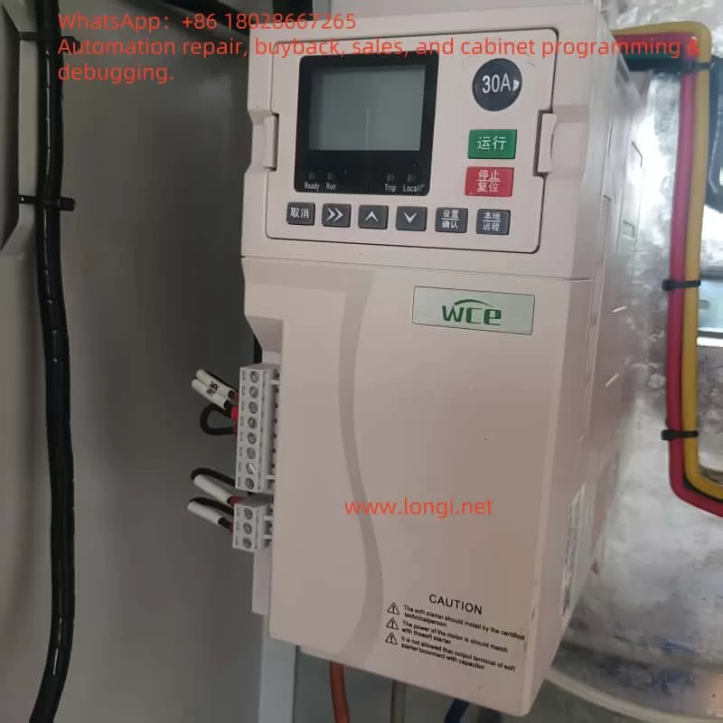
The operation panel (HMI) of the SCKR1 series soft starter is the core interface for user interaction, offering parameter configuration, status monitoring, and fault diagnosis. Below are its main functions (refer to PAGE16, 6.1 Operation Panel):
- Display Screen:
- Shows real-time status (e.g., current, power, motor temperature) and programming details.
- Parameter 8D allows selection between real-time current or motor power display.
- The bottom half of the screen can switch between options like soft starter status, motor temperature, current, and power using the “▲” and “▼” buttons.
- Button Functions:
- Menu Navigation Keys (▲/▼): Switch between menu options, parameters, or adjust parameter values.
- MENU Key: Enter menu or parameter editing mode, save parameter changes (includes STORE function).
- EXIT Key: Exit menu or parameter editing, cancel unsaved changes.
- ALT Key: Used with F1/F2 to access function logs or debugging tools.
- F1/F2 Shortcut Keys: Quick access to common tasks (functions defined by parameters 8B and 8C).
- L/R Key: Switch between Local and Remote control modes.
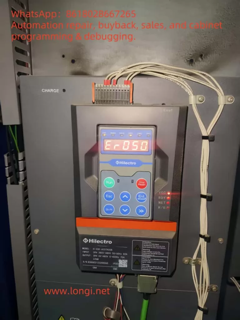
- Status LED Indicators:
- Ready: Steady on indicates motor stopped and starter ready; blinking indicates waiting for restart delay or temperature check.
- Run: Steady on indicates motor running at full voltage; blinking indicates starting or stopping.
- Trip: Steady on indicates starter tripped; blinking indicates warning state.
- Local: Steady on indicates local control mode; off indicates remote control mode.
- If all LEDs are off, it indicates no control voltage.
- Synchronization Function:
- The operation panel syncs with the soft starter’s parameters. If a different panel is inserted, a confirmation message appears, allowing the user to copy parameters from the panel to the starter or vice versa.
2. How to Initialize Parameters
Initializing parameters ensures the soft starter matches the motor (refer to PAGE7, 3.1 Setting Procedure Summary):
- Preparation:
- Ensure no power voltage is applied before connecting cables.
- Complete physical installation and control cable connections (see wiring section).
- Initialization Steps:
- Step 1: Apply control voltage (A1, A2 terminals, 220-440 VAC).
- Step 2: Set date and time:
- Press “ALT” + “TOOL” to enter the “Tool” menu.
- Use “▲/▼” to navigate to the “Date/Time” screen.
- Press “ENTER” to enter edit mode.
- Use “▲/▼” to adjust date and time values, press “ENTER” to save.
- Step 3: Quick setup (for common applications):
- Press “MENU” to enter the main menu.
- Use “▲/▼” to select “Fast Setting,” press “ENTER” to access.
- Find your application in the list, press “ENTER” to start setup.
- Step 4: If no matching application, use the standard menu:
- Return to the main menu, select “Standard Menu.”
- Navigate to “Motor Data 1,” edit parameter 1A (motor rated current) to match the motor nameplate.
- Step 5: Press “EXIT” multiple times to exit the menu.
- Notes:
- For advanced applications, refer to “Extended Menu” (PAGE31) and parameter descriptions (PAGE35).
- Use the built-in simulation tool (3.3 Simulation Tool) to verify wiring and control logic.
3. How to Copy Parameters to Another Soft Starter
The operation panel supports parameter copying for easy configuration of multiple devices (refer to PAGE16, 6.1 Operation Panel):
- Steps:
- Step 1: Save parameters to the operation panel on the source soft starter:
- Press “MENU,” enter “Load/Save Settings” (PAGE35).
- Select “Save to Display,” press “ENTER” to save.
- Step 2: Remove the panel and insert it into the target soft starter.
- Step 3: When the target device detects the new panel, it displays “New Display Detected”:
- Use “▲/▼” to select “Display to Starter.”
- Press “MENU” to confirm; parameters will be copied to the target starter.
- Notes:
- If parameters don’t take effect, the target device loads default values; check compatibility.
- Ensure both devices are of the same model to avoid parameter conflicts.
4. How to Set and Remove a Password
Password protection restricts parameter modifications (refer to PAGE28-29, 9.2 Parameter Write Protection & 9.3 Access Password):
- Set a Password:
- Step 1: Press “MENU,” enter “Programming Menu.”
- Step 2: Navigate to “Access Password” (parameter 15A).
- Step 3: Enter a new password (default is 0000), press “ENTER” to save.
- Step 4: Set “Parameter Write Protection” (parameter 15B) to “Read Only” to restrict changes.
- Remove a Password:
- Step 1: Enter the “Access Password” menu.
- Step 2: Input the current password, press “ENTER” to verify.
- Step 3: Change the password to “0000,” set parameter 15B to “Read/Write” to remove protection.
- Notes:
- If the password is forgotten, contact the supplier for a reset, which may require a factory reset.
5. How to Use External Terminal Start Mode
External terminal start is achieved via remote control inputs (refer to PAGE9, 4.4 Control Cable):
- Configuration:
- The soft starter has 3 fixed remote inputs (e.g., C53, C54), supporting low-voltage, low-current control.
- Press “L/R” to switch to remote mode (Local LED off).
- Wiring:
- Start: Short C53-C54 (start input).
- Stop: Open C53-C54.
- Reset: Short another input pair (configurable, see parameter 6M).
- Parameter Settings:
- In the “Input” menu (PAGE74, 6 Input), configure parameters 6A/6F (input functions) to “Start/Stop/Reset.”
- Notes:
- Ensure correct wiring; test by observing the corresponding LED activation.
6. How to Implement Bypass Control
Bypass control bypasses the soft starter once the motor reaches full speed (refer to PAGE15, 5.2 Bypass Contactor):
- Built-in Bypass:
- Models from 5.5 kW to 500 kW have built-in bypass, requiring no external contactor.
- Automatically switches; no additional operation needed during runtime.
- External Bypass:
- Models without built-in bypass require an external bypass contactor.
- Contactor AC1 rating ≥ motor current.
- Wiring: Connect the bypass contactor in parallel with the soft starter outputs (2/T1, 4/T2, 6/T3).
- Control:
- Configure relay outputs (parameters 7A-7L) to “Bypass,” which close when the motor reaches full voltage, activating the bypass contactor.
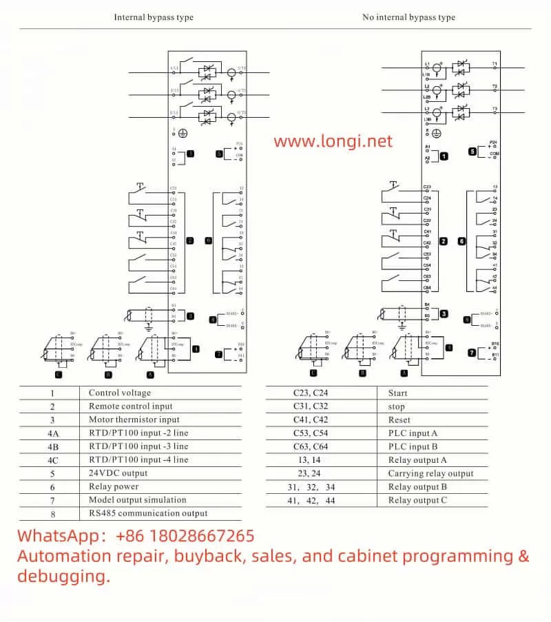
7. Wiring (Main Circuit and Control Circuit)
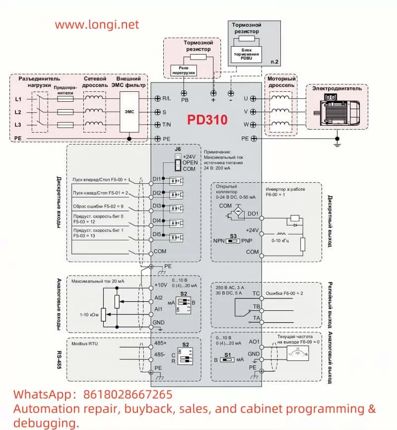
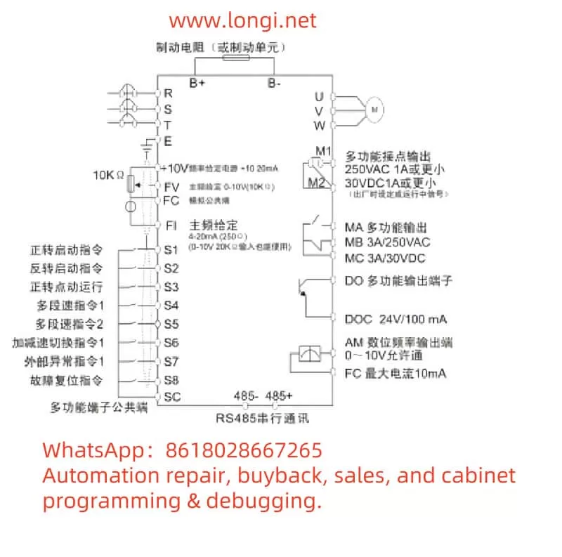
Main Circuit Wiring (refer to PAGE10-11, 4.8-4.9)
- Input Terminals: 1/L1, 3/L2, 5/L3 connect to three-phase power.
- Output Terminals: 2/T1, 4/T2, 6/T3 connect to the motor.
- Grounding: 5.5-55 kW models have 1 ground terminal at the input; 75-500 kW models have 2 (one at input, one at output).
- Schematic (simplified text representation; refer to the manual for actual diagrams):
  [Power L1]---[1/L1]   [2/T1]---[Motor U]
  [Power L2]---[3/L2]   [4/T2]---[Motor V]
  [Power L3]---[5/L3]   [6/T3]---[Motor W]
  [Ground]------[Earth]
Control Circuit Wiring (refer to PAGE8-9, 4.2-4.4)
- Control Voltage: A1, A2 terminals connect to 220-440 VAC.
- Remote Inputs: C53-C54, etc., connect to external switches.
- Schematic:
  [220-440V]---[A1]   [C53]---[Start Switch]---[C54]
               [A2]   [Other Inputs]---[Stop/Reset Switch]
8. Key Parameters
Below are critical parameters (refer to PAGE73-76, 12.2 Parameter Value):
- 1A: Motor rated current, matches the motor nameplate.
- 2A-2D: Start mode, ramp time, initial current, current limit; affect start performance.
- 4A-4F: Protection settings, e.g., start timeout, undercurrent, instantaneous overcurrent.
- 6A-6F: Input functions, define external terminal roles.
- 7A-7L: Relay output functions, e.g., bypass control.
- 15A-15B: Access password and write protection.
9. Fault Codes, Meanings, and Solutions
Below are common fault codes (refer to PAGE81-82, 13.5 Trip Code):
- 1 – Starting Time Limit:
- Meaning: Start time exceeded.
- Solution: Check parameter 4A, extend start time, or adjust load.
- 2 – Motor Overload:
- Meaning: Motor overloaded.
- Solution: Check motor load, adjust parameters 1B-1D, cool down and restart.
- 8 – Power Down/Power Circuit:
- Meaning: Power failure or circuit not energized.
- Solution: Check main contactor and fuses.
- 15 – Starter Communication:
- Meaning: Communication failure.
- Solution: Check interface connections, contact supplier.
For more faults, refer to PAGE81-82. Disconnect power before troubleshooting.