1. Introduction
In industrial automation, PLCs (Programmable Logic Controllers) are core control devices. The Siemens S7-300 PLC series is widely used in various automation production lines and control systems. As system complexity and communication protocols increase, communication issues between the PLC and connected devices have become common faults. This article will detail the common communication faults encountered during the use of Siemens S7-300 PLCs, including error diagnostics, clearing the error buffer, restarting communication, and common network configuration issues, while providing specific troubleshooting steps.
2. Common Communication Faults Analysis
Siemens S7-300 PLCs often need to exchange data with other devices in industrial automation systems, such as HMIs (Human-Machine Interfaces), remote I/O modules, variable frequency drives, sensors, etc. The following are some common types of communication faults and their analysis:
- PROFINET Communication Errors
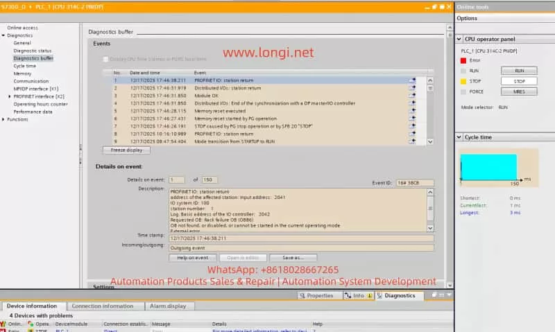
When using PROFINET for device interconnection, communication between the PLC and network devices may be interrupted or erroneous. A common error is “PROFINET: station return,” which typically indicates that the device did not respond as expected, possibly due to incorrect IP address settings, network cable issues, or improper device configuration. - BUS2F Bus Fault
When the SF (System Fault) indicator on the PLC lights up red, it typically indicates a communication issue on the PROFIBUS or PROFINET bus. Common causes include module mismatch, hardware failure, or address conflicts. - I/O Module Unresponsiveness
In complex systems, communication errors between the PLC and I/O modules can prevent the I/O modules from responding correctly. Diagnostic information often shows “Distributed I/O: station return,” indicating that a module failed to synchronize correctly.
3. Diagnostic Steps and Solutions
When encountering communication faults, follow these steps for diagnosis:
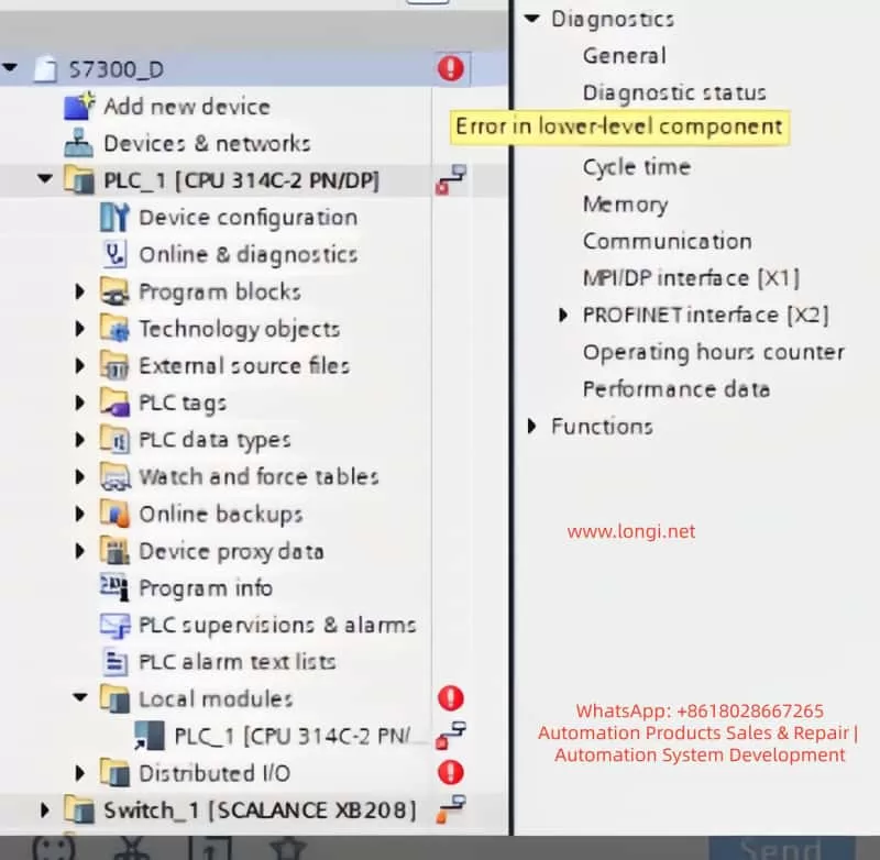
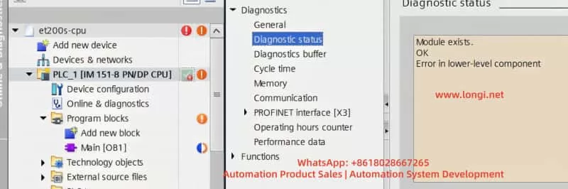
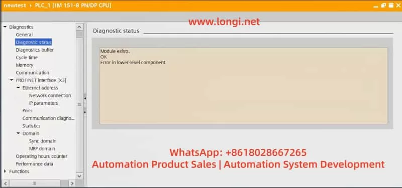
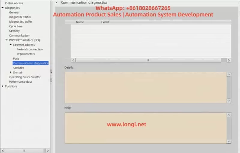
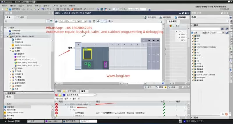
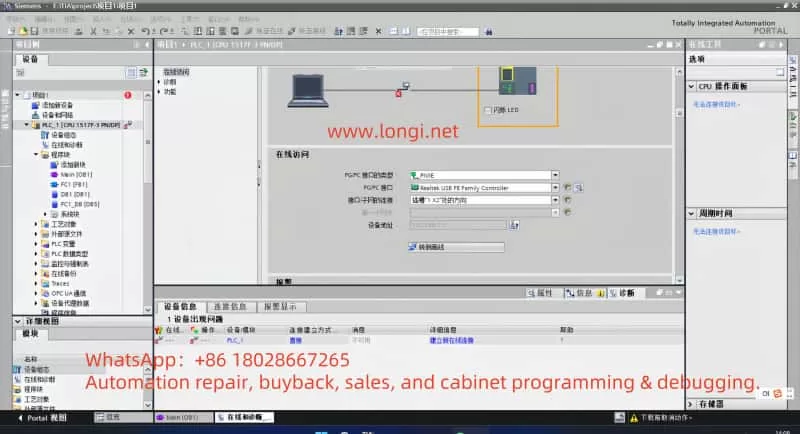
1. Check PLC Diagnostic Information
In TIA Portal, navigate to the Online and Diagnostics tab to view detailed diagnostic information for the PLC. This can help quickly identify fault codes and the affected devices. Key diagnostic steps include:
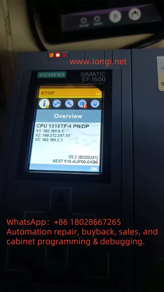
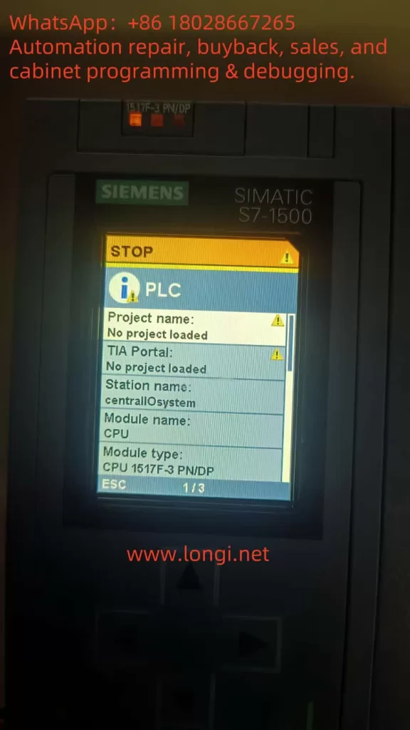
- Open Diagnostic Status and observe the status of Fault LED and Error LED. If the BUS2F or SF indicator is red, it indicates a communication issue.
- Access the Diagnostic Buffer to view detailed event logs. These logs will help pinpoint the root cause, such as network issues, module failures, or configuration errors.
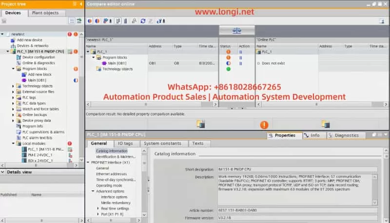
2. Clear the Error Buffer
When communication errors occur, the first step is to clear the error buffer. This prevents the accumulation of obsolete error logs and ensures accurate diagnostics. Follow these steps:
- In TIA Portal, select PLC_1 and navigate to the Diagnostics Buffer section.
- In the diagnostic window, click the Clear button to remove previous error logs. This will clear the error state, making it easier to diagnose the current issue.
3. Restart PLC Communication
If clearing the error buffer doesn’t resolve the issue, try restarting the PLC communication. This can be done in two ways:
- Restart PLC Operation: In TIA Portal, right-click the PLC and select “Restart” or “Stop/Start” options.
- Manual Restart: If restarting from TIA Portal doesn’t work, press the RESET button on the PLC, or power cycle the PLC to restart it.
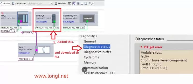
4. Check Device Connections and Network Configuration
The root cause of communication problems is often related to device connections or network configuration errors. Perform the following checks:
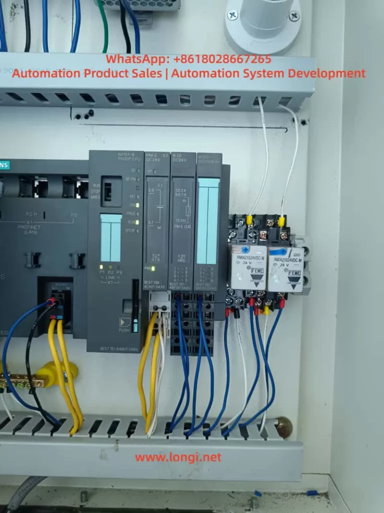
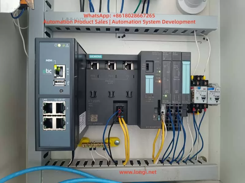
- Check Device Connections: Ensure all devices (e.g., SCALANCE XB208, remote I/O modules, HMI) are correctly connected to the PLC and that network cables are not damaged.
- Check IP Address Settings: Ensure that the PLC and all connected devices have correctly configured IP addresses and subnet masks. Address conflicts or incorrect settings are common causes of communication failures.
- Network Topology: Verify that the network topology is correct, with all devices on the appropriate network segments, and ensure there are no loops or address conflicts.
5. Update Firmware
Firmware mismatches are another common cause of communication faults. After checking the hardware version of the devices, ensure that the firmware on both the SCALANCE XB208 and the PLC is compatible. If the firmware is outdated, update it by following these steps:
- Access Device Management Interface: Log into the device’s web interface to view its firmware version.
- Download and Install Updates: Visit Siemens’ website to download the latest firmware and perform the update. After updating, restart the device to apply the new firmware.
6. Test and Verify the Network
After completing all troubleshooting steps, network communication should be tested to ensure that it has been restored. Use the following methods to verify if the network is functioning properly:
- Use TIA Portal’s diagnostic tools to perform network tests and check whether the communication between the PLC and other devices has been restored.
- Ping the PLC and devices using the ping command to test network connectivity.
4. Conclusion
PLC communication problems are common in industrial automation, especially in systems involving multiple devices and complex networks. Through systematic troubleshooting steps, users can effectively diagnose and resolve common PROFINET and PROFIBUS communication issues. Clearing the error buffer, restarting communication, checking device connections, and updating firmware are key steps in resolving communication faults.
This article provides detailed steps for troubleshooting communication issues in Siemens S7-300 PLCs, and aims to help users restore normal operation and improve system reliability and stability.