Posted on

Understanding and Resolving AL.72.8 Fault in Sanyo Denki SanMotion RS2 Series Servo Drivers

Introduction

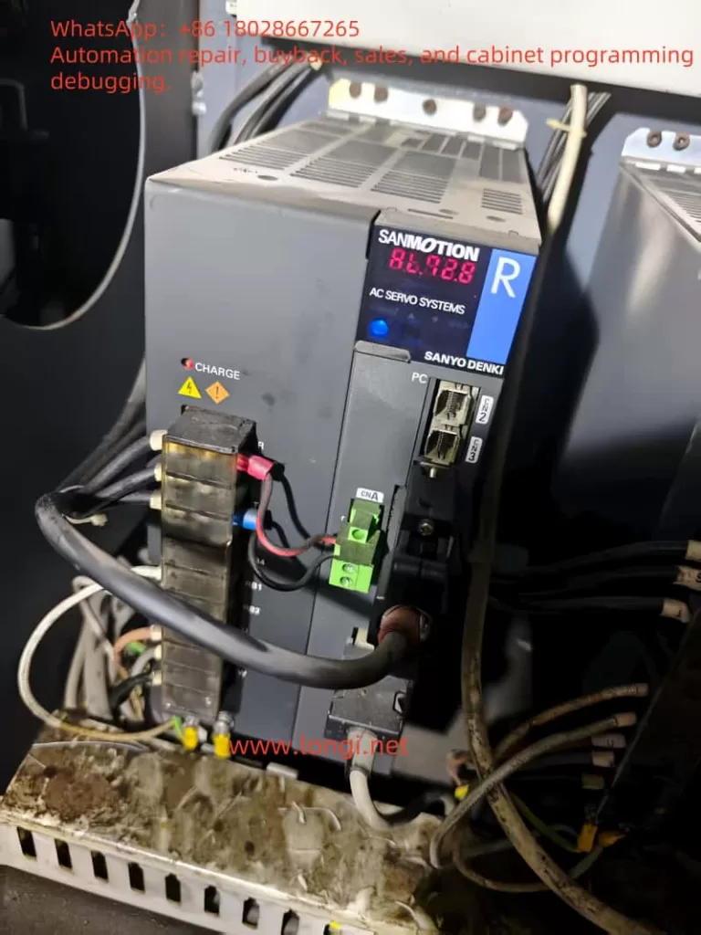
Sanyo Denki’s SanMotion RS2 series servo drivers are renowned for their precision and reliability in industrial automation applications, such as robotics, CNC machines, and automated manufacturing systems. These drivers are designed to deliver high-performance motion control, but like any sophisticated electronic system, they can encounter faults that disrupt operations. One such fault is the AL.72.8 error code, which, based on available information, likely indicates a ±12V power supply abnormality. This fault can halt critical operations, making it essential for technicians and engineers to understand its causes, troubleshooting steps, and preventive measures. This article provides a comprehensive guide to diagnosing and resolving the AL.72.8 fault, ensuring minimal downtime and sustained system performance.

Understanding the AL.72.8 Fault Code

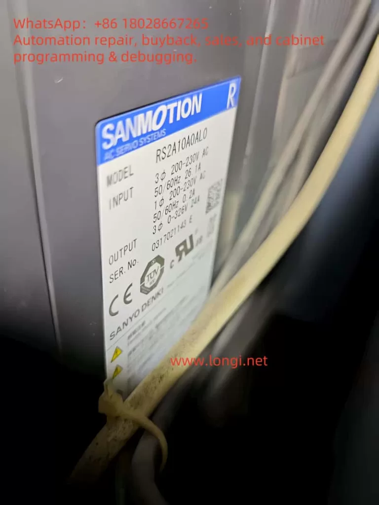
The AL.72.8 fault code, sometimes displayed as “72H” in hexadecimal format, is believed to indicate an abnormality in the ±12V power supply within the Sanyo Denki SanMotion RS2 series servo driver. The ±12V supply is a critical component that powers various control circuits, including:

  • Encoder Interfaces: For precise motor position feedback.
  • Communication Ports: Such as RS-485 or CANopen, used for interfacing with control systems.
  • Logic Circuits: For processing control signals and ensuring proper operation.

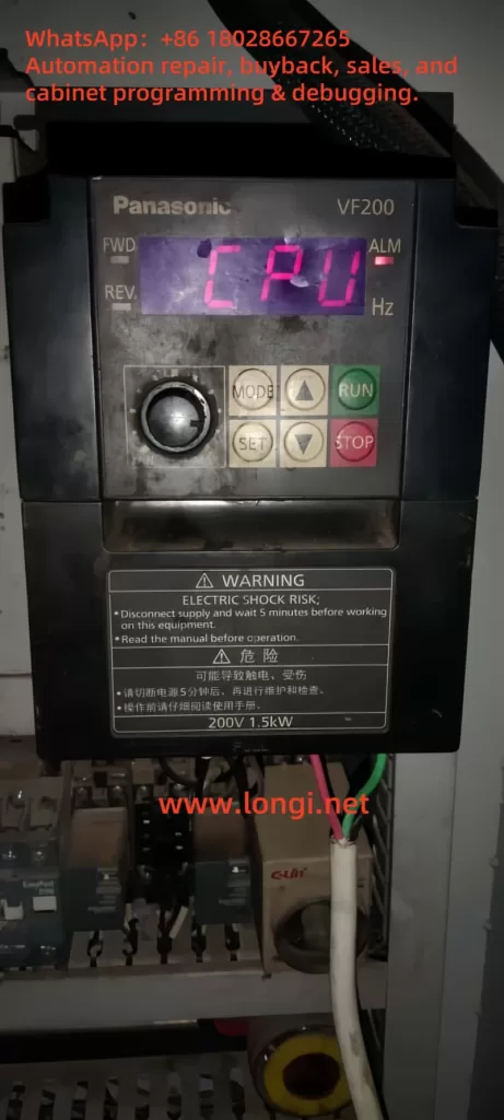
When the ±12V supply deviates from its nominal range (typically ±12V ±10%) or fails entirely, it can lead to erratic behavior, loss of control, or complete system shutdown. The fault is displayed prominently on the driver’s digital panel, as observed in user-provided images, signaling the need for immediate troubleshooting.

Potential Causes of AL.72.8

Several factors can trigger the AL.72.8 fault. Understanding these causes is the first step toward effective resolution:

  1. Internal Power Supply Failure:
    • The servo driver relies on an internal DC-DC converter to generate the ±12V supply from the main AC input (typically 200-240V AC). Failures in this converter, due to component wear, overheating, or manufacturing defects, can result in unstable or absent ±12V output.
    • Symptoms may include intermittent faults, random resets, or loss of communication with the motor or controller.
  2. Short Circuit or Open Circuit:
    • A short circuit in the ±12V line can cause excessive current draw, triggering protective circuits or damaging components.
    • An open circuit, conversely, prevents voltage from reaching critical components, leading to operational failures.
  3. Damaged Components:
    • Components on the control board, such as operational amplifiers, logic ICs, or microcontrollers powered by the ±12V supply, may fail due to overvoltage, overheating, or prolonged use.
    • Visual signs include burnt, discolored, or swollen components, particularly electrolytic capacitors.
  4. Incorrect Wiring:
    • While the ±12V supply is typically internal, external modifications or incorrect wiring during maintenance can introduce faults.
    • Unauthorized changes or loose connections can disrupt the power supply chain.
  5. Main Power Supply Issues:
    • The main AC input voltage must remain within 200-240V AC (±10%) for proper operation. Fluctuations, spikes, or sags can stress the internal DC-DC converter, affecting the ±12V supply.
    • Phase imbalances or power quality issues can exacerbate this problem.
  6. Aging Components:
    • Electrolytic capacitors, commonly used in power supply circuits, degrade over time, losing capacitance or increasing equivalent series resistance (ESR). This can destabilize the ±12V supply, especially under load.
    • Other components, such as voltage regulators, may also deteriorate with prolonged use.

The following table summarizes the potential causes and their impacts:

CausePotential Impact
Internal Power Supply FailureUnstable or missing ±12V supply, system shutdown
Short Circuit/Open CircuitExcessive current or no voltage to circuits
Damaged ComponentsAbnormal voltage behavior, circuit failure
Incorrect WiringDisrupted power supply, erratic operation
Main Power Supply IssuesStress on internal converter, voltage instability
Aging ComponentsReduced performance, intermittent faults

Troubleshooting the AL.72.8 Fault

Resolving the AL.72.8 fault requires a systematic approach to identify and address the root cause. Below are detailed troubleshooting steps:

  1. Verify Main Power Supply:
    • Use a true RMS multimeter to measure the input AC voltage at the driver’s power terminals, ensuring it is within 200-240V AC (±10%).
    • Check for voltage stability using a power quality analyzer if fluctuations are suspected.
    • Ensure the power source is free from phase imbalances or excessive noise.
  2. Inspect Internal and External Wiring:
    • With the power off and proper safety precautions (e.g., wearing ESD-safe gear), open the servo driver.
    • Visually inspect internal wiring for loose connections, burnt wires, or signs of overheating.
    • Check external connections, such as those to the motor or controller, for damage or improper wiring.
  3. Measure ±12V Supply:
    • Locate the ±12V test points on the control board, as specified in the RS2 series service manual.
    • With the driver powered on (in a safe, servo-off state), measure the voltage using a multimeter. The reading should be close to ±12V with minimal ripple (<1% of nominal voltage).
    • If the voltage is out of range, trace the ±12V lines to identify the point of failure.
  4. Check for Short Circuits:
    • Disconnect the driver from power.
    • Use a multimeter in continuity mode to check for shorts between the ±12V lines and ground or other circuits.
    • Measure resistance across the ±12V lines; it should be high (open circuit) unless intentional loads are present.
  5. Inspect Components:
    • Examine the control board for visible damage, such as bulging capacitors, discolored resistors, or burnt ICs.
    • If possible, measure the resistance or capacitance of suspect components and compare with expected values.
  6. Use Diagnostic Tools:
    • Utilize Sanyo Denki’s SANMOTION R Setup Software to access fault logs and additional error codes.
    • Monitor parameters related to power supply status to gain further insight into the fault.
  7. Consult Manufacturer’s Documentation:
    • Refer to the RS2 series manual for specific troubleshooting flowcharts or procedures for AL.72.8.
    • Check for service bulletins or known issues related to this fault code.
  8. Contact Technical Support:
    • If the issue persists, contact Sanyo Denki’s technical support or an authorized service center. Provide the model number, serial number, fault code, and detailed observations from your troubleshooting efforts.
    • Support contact details include:

    The following table outlines the troubleshooting steps and their objectives:

    StepObjective
    Verify Main Power SupplyEnsure input voltage is within specifications
    Inspect WiringIdentify loose or damaged connections
    Measure ±12V SupplyConfirm voltage stability and range
    Check for Short CircuitsDetect electrical faults in ±12V lines
    Inspect ComponentsIdentify damaged or faulty components
    Use Diagnostic ToolsAccess detailed fault logs and parameters
    Consult DocumentationFollow manufacturer’s troubleshooting guide
    Contact Technical SupportObtain expert assistance for unresolved issues

    Preventive Measures

    Preventing the AL.72.8 fault and similar issues requires proactive maintenance and careful system design. Here are key preventive measures:

    1. Regular Maintenance:
      • Schedule inspections every 6-12 months, depending on the operating environment.
      • Clean the driver to remove dust and debris, which can cause overheating or electrical issues.
      • Replace aging components, such as electrolytic capacitors, as per the manufacturer’s maintenance schedule.
    2. Stable Power Supply:
      • Install voltage stabilizers or uninterruptible power supply (UPS) systems to protect against power fluctuations.
      • Ensure the electrical panel includes overcurrent protection and surge suppression devices.
    3. Proper Installation:
      • Mount the servo driver vertically to optimize cooling and ensure adequate airflow.
      • Install in a clean, dry, and well-ventilated environment to prevent overheating and contamination.
    4. Monitor System Performance:
      • Use the driver’s built-in monitoring functions or diagnostic software to log temperatures, voltages, and other parameters.
      • Set up alerts for abnormal conditions, such as voltage deviations or temperature increases.
    5. Training and Documentation:
      • Train maintenance personnel on the specific RS2 series model and its fault codes.
      • Maintain up-to-date documentation, including service manuals and wiring diagrams, for quick reference.

    Conclusion

    The AL.72.8 fault code in Sanyo Denki SanMotion RS2 series servo drivers likely indicates a ±12V power supply abnormality, which can disrupt critical control functions. Potential causes include internal power supply failures, short circuits, damaged components, or main power supply issues. By following a systematic troubleshooting approach—verifying the main power supply, inspecting wiring, measuring voltages, and consulting technical support—technicians can effectively diagnose and resolve the issue. Preventive measures, such as regular maintenance, stable power supply, and proper installation, are essential for minimizing the occurrence of this fault and ensuring the longevity of the servo system. For further assistance, refer to the official Sanyo Denki documentation or contact their technical support team.

    Posted on

    Panasonic VF200 Series Inverter “CPU” Fault and ALARM Light Resolution Guide

    1. Introduction

    The Panasonic VF200 series inverter is a widely used device in industrial automation, known for its efficiency, reliability, and versatility. This series supports single-phase 200V (0.2kW to 2.2kW) and three-phase 400V (0.75kW to 15kW) power supplies, making it suitable for various motor control applications. However, users may encounter issues during operation, one of the most common and troubling being the “CPU” fault code displayed on the inverter’s screen accompanied by the ALARM light. This fault indicates an abnormality in the inverter’s core control system, potentially causing the device to stop functioning and disrupting production efficiency. This article will provide a detailed analysis of the “CPU” fault, its possible causes, and a systematic approach to troubleshooting and resolving the issue to help users quickly restore normal operation.

    CPU ALARM

    2. Meaning of the “CPU” Fault

    In the Panasonic VF200 series inverter, when the display shows the “CPU” fault code and the ALARM light is on, it typically indicates a problem with the inverter’s Central Processing Unit (CPU). The CPU is the “brain” of the inverter, responsible for executing control algorithms, processing input and output signals, and coordinating the overall operation of the device. When the CPU detects an abnormality in itself or related systems, the inverter enters protection mode, stops operation, and alerts the user by displaying the “CPU” code and lighting the ALARM lamp.

    According to the VF200 series user manual and technical documentation, the “CPU” fault may be associated with other anomalies such as instantaneous overcurrent (OC1-3) or temperature abnormalities (OH). This suggests that the “CPU” error may not solely be a hardware issue with the CPU but could also be triggered indirectly by external conditions or system operational states. Therefore, understanding the potential causes of this fault is crucial.

    3. Possible Causes of the “CPU” Fault

    The occurrence of the “CPU” fault can be triggered by various factors. Below are detailed analyses of several common causes:

    1. Power Supply Issues

    • Voltage Instability: The VF200 series inverter has strict requirements for input power. If the power supply voltage exceeds the rated range (single-phase 200V or three-phase 400V) or fluctuates, it may lead to insufficient power or overvoltage damage to the CPU.
    • Power Interference: Surges or electromagnetic interference (EMI) in the power supply can disrupt the normal operation of the CPU, especially in industrial environments with poor power quality.

    2. Overheating Issues

    • Temperature Abnormality (OH): If the internal temperature of the inverter is too high, it may be due to poor ventilation, high ambient temperature, or a malfunctioning cooling fan (FAn). High temperatures can affect the stability of the CPU and even trigger faults.
    • Overloading: Operating under high load conditions for extended periods can lead to inadequate heat dissipation, further exacerbating temperature increases.

    3. Overcurrent Issues

    • Instantaneous Overcurrent (OC1-3): Motor failures, sudden load changes, or wiring errors can cause the current to exceed the inverter’s rated value. This situation may place excessive stress on the CPU, triggering the protection mechanism and displaying the “CPU” error.
    • Improper Parameter Settings: If the current limit parameters are set incorrectly, it may fail to effectively prevent overcurrent conditions.

    4. Firmware or Software Issues

    • Firmware Corruption: Firmware is the software foundation for CPU operation. If the firmware is corrupted during an update or due to electrical interference, the CPU may not function properly.
    • Parameter Errors: Parameters set by the user that do not match the actual application may cause the CPU to execute abnormal instructions.

    5. Hardware Failures

    • CPU or Control Board Damage: Long-term use, manufacturing defects, or physical damage can lead to hardware failures in the CPU or its control board, such as circuit board burnout or component aging.
    • Connection Issues: Loose or poor internal connections may disrupt data communication between the CPU and other modules.

    6. External Interference

    • Electromagnetic Interference: High-power equipment commonly found in industrial environments can generate strong electromagnetic interference, affecting the CPU’s signal processing capabilities.
    • Poor Grounding: High grounding resistance can lead to the accumulation of electrical noise, interfering with CPU operation.
    VF200

    4. Steps to Troubleshoot and Resolve the “CPU” Fault

    To effectively resolve the “CPU” fault, users should follow these systematic steps for troubleshooting and resolution:

    1. Initial Checks and Safety Preparations

    • Power Off: According to the warning labels on the inverter, disconnect the power and wait at least 5 minutes to ensure the internal capacitors are discharged, avoiding the risk of electric shock.
    • Record Status: Note the operating conditions when the “CPU” fault occurred (such as load, ambient temperature, etc.) to provide clues for subsequent diagnosis.

    2. Check Power Supply Conditions

    • Measure Voltage: Use a multimeter to measure the input power voltage, ensuring it is within the rated range for single-phase 200V (0.2kW to 2.2kW) or three-phase 400V (0.75kW to 15kW) and free from significant fluctuations.
    • Check Grounding: Confirm that the grounding resistance is less than 10 ohms to eliminate interference caused by poor grounding.

    3. Check for Overheating Issues

    • Ambient Temperature: Ensure the operating environment temperature is between 0°C and 40°C, and check if the ventilation openings are blocked.
    • Cooling Fan: Verify if the fan is operating normally; replace it if faulty.
    • Clean the Device: Use compressed air to remove dust from inside the inverter to ensure proper heat dissipation.

    4. Check for Overcurrent Issues

    • Load Check: Ensure the motor load does not exceed the inverter’s rated capacity and check for motor short circuits or mechanical jams.
    • Wiring Check: Inspect the wiring between the inverter and the motor to ensure it is correct and secure.
    • Parameter Adjustment: Use the “MODE,” “SET,” “UP,” and “DOWN” keys to access parameter settings and check the current limit parameters, ensuring they are within 1% to 200% of the rated output current.

    5. Reset and Firmware Check

    • Power Reset: After powering off and waiting 5 minutes, power on again to see if the “CPU” error disappears.
    • Restore Factory Settings: If the issue persists, follow the user manual to restore factory settings and then reconfigure necessary parameters.
    • Firmware Update: Contact technical support to obtain the latest firmware and follow the instructions to update it.

    6. Hardware Inspection

    • Visual Inspection: Open the inverter casing and check the control board for signs of burning, odors, or damaged components.
    • Connection Repair: If loose connections are found, secure them with insulating tape and re-tighten.
    • Component Replacement: If hardware damage is severe, contact Panasonic after-sales service to replace the original control board.

    7. Reduce External Interference

    • Isolate Interference Sources: Separate the inverter from high-power equipment or install shielding covers.
    • Use Shielded Cables: Ensure that control signal lines and power lines use shielded cables to reduce electromagnetic interference.

    8. Testing and Verification

    • Operation Test: After completing the above steps, restart the inverter and observe if the “CPU” error is resolved.
    • Diagnostic Function: Use the inverter’s error log function to check for other related fault codes (such as OC1-3, OH, etc.).

    9. Seek Professional Support

    • If the issue remains unresolved, contact Panasonic technical support, providing detailed fault information, model (VF200), and troubleshooting records for remote diagnosis or on-site repair.

    5. Preventive Measures for “CPU” Faults

    To prevent the recurrence of “CPU” faults, users can take the following preventive measures:

    1. Regular Maintenance
    • Clean dust every 6 months, check wiring and fan status to ensure proper heat dissipation and electrical connections.
    1. Power Optimization
    • Install voltage stabilizers or UPS to ensure stable power supply and avoid voltage spikes.
    1. Environmental Management
    • Keep the operating environment clean, dry, and avoid high temperatures and humidity, ensuring good ventilation.
    1. Firmware Management
    • Regularly check firmware versions, back up parameters before updating to ensure software stability.
    1. Standardized Operation
    • Train operators to set parameters correctly according to the user manual to avoid malfunctions caused by incorrect operations.

    6. Conclusion

    The “CPU” fault displayed on the Panasonic VF200 series inverter, accompanied by the ALARM light, is a serious issue that requires prompt attention. It can be caused by power instability, overheating, overcurrent, firmware issues, hardware failures, or external interference. By following the systematic troubleshooting steps provided in this article, users can start with checking power and environmental conditions, then delve into hardware and firmware aspects to identify the root cause and apply targeted solutions. Additionally, regular maintenance and optimizing the operating environment are key to preventing faults. If self-troubleshooting fails, contacting Panasonic’s official support is advisable. Through these methods, users can not only resolve the current “CPU” fault but also enhance the long-term stability and lifespan of the equipment, ensuring reliable support for industrial production.


    Posted on

    Detailed Explanation and Troubleshooting of SC1 Fault in Panasonic VF0 Inverter

    In industrial automation, the inverter plays a crucial role in motor speed regulation and energy saving. Its stability directly affects the efficiency and reliability of the entire system. This article focuses on the SC1 fault code commonly seen in the Panasonic VF0 series inverter, analyzing its meaning, root causes, and practical troubleshooting steps.

    1. What Does SC1 Fault Indicate?

    According to the Panasonic VF0C Inverter Manual, the SC1 code signifies an overcurrent or abnormal heat generation at the heatsink during acceleration. It is a protective mechanism to prevent IGBT modules or internal circuits from damage caused by excessive current or temperature spikes.

    • SC1: Overcurrent or overheating during motor acceleration phase
    • Main protection target: IGBT modules, bus capacitors, cooling fans
    • Trigger timing: During the acceleration ramp-up of the motor

    2. Common Causes of SC1 Fault

    SC1 faults can arise due to issues in power electronics, load mechanics, thermal conditions, or control parameters. The most frequent causes include:

    a) Output Short Circuit or Ground Fault

    Faulty motor cables or incorrect wiring (e.g., shorted U/V/W terminals or ground leakage) can cause surge currents during motor start-up.

    b) Heavy or High-Inertia Load

    Excessive mechanical load, locked rotor, or applications with high inertia (e.g., conveyor belts, compressors) may draw high start-up current, exceeding inverter ratings.

    c) Cooling System Failure

    Fan failure, clogged heatsinks, or poor cabinet ventilation can lead to temperature rise and SC1 alarm.

    d) Improper Parameter Settings

    A too-short acceleration time (e.g., 0.1~1 sec) will force the inverter to ramp up frequency quickly, resulting in high current output.

    e) Input Voltage Instability

    Low input voltage increases the output current demand, especially during acceleration, potentially triggering overcurrent faults.

    sc1_fault_diagram

    3. Troubleshooting and Solution Steps

    Here are practical steps to diagnose and resolve SC1 alarms:

    Step 1: Check Output Wiring and Motor Load

    • Use a multimeter to test U/V/W terminals for shorts or ground leakage.
    • Inspect motor cables for damage or poor connections.
    • Rotate the motor shaft manually to ensure it’s not mechanically jammed.

    Step 2: Inspect Cooling Fan and Heat Dissipation

    • Open the inverter cover and check if the cooling fan is running.
    • Clean dust on the heatsink with compressed air.
    • Ensure the electrical cabinet has proper ventilation, especially in summer.

    Step 3: Optimize Parameter Settings

    Access parameter setting mode (MODE → SET), then adjust:

    Parameter No.FunctionSuggested Setting
    Pr.01Acceleration time3~5 seconds
    Pr.13Overcurrent limitMid or wide range
    Pr.90Heatsink temperature limitAvoid low threshold

    Tip: Always record the original settings before making changes.

    Step 4: Measure Input Voltage

    • Check the input voltage on the terminal block to ensure it is within the rated range (200~230V).
    • If voltage is low, consider improving incoming power cable thickness or stability.

    Step 5: Evaluate Load Application

    • For high-inertia loads, use S-curve acceleration or external soft-start mechanisms.
    • Reduce frequency of frequent starts/stops if possible.

    4. Real-World Case Study

    A Panasonic VF0 inverter (model BFV00152GK, 1.5kW) experienced frequent SC1 faults. On-site checks revealed:

    • Internal fan failure
    • Acceleration time set to only 0.5 seconds
    • Enclosure internal temperature reached over 45°C

    Fixes Applied:

    • Replaced fan and cleaned heatsink
    • Adjusted Pr.01 (acceleration time) to 3.0 seconds
    • Added top exhaust fan to the control cabinet

    Result: SC1 alarms were eliminated after these corrections.

    5. Preventive Measures

    To minimize SC1 alarms in the future:

    • Periodically clean inverter and cabinet internals
    • Replace consumables like fans and capacitors every 2–3 years
    • Avoid aggressive acceleration settings
    • Add temperature sensors and alarms for heat monitoring
    • Use external torque/speed ramps for sensitive applications
    VF0

    6. Conclusion

    The SC1 code on Panasonic VF0 inverters is a protection feature for acceleration-related overcurrent or thermal overload. It indicates a potential risk that should not be ignored. With proper diagnostics and control parameter tuning, SC1 alarms can be resolved efficiently, ensuring reliable and long-term operation of your automation system.


    Posted on

    Panasonic Inverter VF200 Series User Manual Guide

    Introduction

    The Panasonic Inverter VF200 series is a powerful and flexible variable frequency drive (VFD) equipment widely used in the industrial automation field. This document aims to provide users with a detailed user guide to help them better understand and efficiently operate the VF200 series inverter.


    Function diagram of Panasonic VF200 series inverter operation panel

    1. Operation Panel Function Introduction, Parameter Upload, and Download

    1.1 Operation Panel Function Introduction

    The operation panel of the Panasonic Inverter VF200 series serves as the primary interface for user interaction. It features various functions and indicators to facilitate ease of use and monitoring.

    • Display Section: Displays output frequency, current, linear speed, set frequency, communication station number, abnormality content, various mode displays, and function setting data.
    • FWD/REV Indicators: Green indicators that show the forward/reverse operation status.
    • Panel Potentiometer: Used to set the operating frequency via the operation panel.
    • Alarm (ALM) Indicator: Red indicator that lights up in case of abnormalities or alarms.
    • RUN/STOP Buttons: Buttons to start/stop the inverter.
    • MODE Button: Toggles between various modes such as operation status display, frequency setting, rotation direction setting, control status monitoring, custom settings, function settings, and built-in memory settings.
    • SET Button: Used to switch modes, display data, and store settings.
    • ▲(UP) and ▼(DOWN) Buttons: Used to change data, output frequency, and set the rotation direction when operating via the panel.
    VF200 picture

    1.2 Uploading and Downloading Parameters

    • Uploading Parameters (CPY1): To upload the inverter’s functional parameters to the operation panel’s built-in memory, follow these steps:
      1. Stop the inverter.
      2. Press the MODE button four times to enter the function setting mode.
      3. Press the SET button.
      4. Use the ▲/▼ buttons to select “CPY1”.
      5. Press the SET button and set the value to “UPL”.
      6. Press the SET button again to start the upload process.
    • Downloading Parameters (CPY2): To download the parameters from the operation panel’s built-in memory to the inverter, follow these steps:
      1. Stop the inverter.
      2. Press the MODE button four times to enter the function setting mode.
      3. Press the SET button.
      4. Use the ▲/▼ buttons to select “CPY2”.
      5. Press the SET button and set the value to “dOL”.
      6. Press the SET button again to start the download process.

    1.3 Setting and Eliminating Passwords

    • Setting a Password:
      1. Stop the inverter.
      2. Press the MODE button four times to enter the function setting mode.
      3. Use the ▲/▼ buttons to navigate to parameter P150.
      4. Press the SET button to display the current password.
      5. Use the ▲/▼ buttons to set a new password (range: 0000-9999).
      6. Press the SET button to save the password.
    • Eliminating a Password:
      1. Stop the inverter.
      2. Press the MODE button four times to enter the function setting mode.
      3. Use the ▲/▼ buttons to navigate to parameter P150.
      4. Press the SET button to display the current password.
      5. Set the password to “0000” using the ▲/▼ buttons.
      6. Press the SET button to eliminate the password.

    1.4 Restoring Parameter Initialization

    To restore the inverter’s parameters to their factory default settings, follow these steps:

    1. Stop the inverter.
    2. Press the MODE button four times to enter the function setting mode.
    3. Use the ▲/▼ buttons to navigate to parameter P151.
    4. Press the SET button to display the current setting.
    5. Set the value to “3” using the ▲/▼ buttons.
    6. Press the SET button to restore the parameters to their factory defaults.
    Panasonic VF200 inverter control terminal wiring diagram

    2. External Terminal Control for Forward/Reverse Rotation and PWM Frequency Control

    2.1 Forward/Reverse Rotation Control via External Terminals

    To achieve forward/reverse rotation control via external terminals, connect the relevant control signals to the designated terminals on the inverter.

    • Terminal Configuration:
      • SW1-SW5 (Control Circuit Terminals 4-8): These terminals can be configured to control forward/reverse rotation, start/stop, and other functions.
      • Configuration Steps:
        1. Stop the inverter.
        2. Enter the function setting mode by pressing the MODE button four times.
        3. Navigate to parameters P036-P040 using the ▲/▼ buttons.
        4. Set the desired function (e.g., forward/reverse, start/stop) to the corresponding terminal using the ▲/▼ buttons.
        5. Press the SET button to save the settings.

    2.2 PWM (Pulse) Frequency Control

    To control the inverter’s output frequency via PWM signals, follow these steps:

    • Terminal Configuration:
      • Terminal 7 (SW4) and Terminal 8: These terminals are used to receive PWM frequency control signals.
      • Configuration Steps:
        1. Stop the inverter.
        2. Enter the function setting mode by pressing the MODE button four times.
        3. Navigate to parameter P087 using the ▲/▼ buttons.
        4. Set the value to “1” to enable PWM frequency control.
        5. Press the SET button to save the setting.
        6. Connect the PWM signal source to terminals 7 and 8 according to the wiring diagram provided in the manual.
    • Additional Settings:
      • P088: Sets the number of PWM cycles to average for frequency calculation.
      • P089: Sets the PWM signal period.

    By following this guide, users can effectively utilize the Panasonic Inverter VF200 series, leveraging its advanced features and flexible control options to meet various industrial automation needs.