Introduction
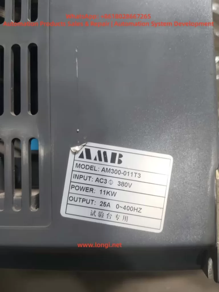
The AMB300 series of Ampower inverters are high-performance, multifunctional inverters widely used in the field of industrial automation. This article will provide a detailed introduction to the operation panel functions, password setting and removal, parameter access restrictions, setting parameters back to factory defaults, as well as how to achieve external terminal forward/reverse rotation control and external potentiometer speed regulation for this series of inverters. Additionally, it will explore common fault codes and their solutions to help users better use and maintain the AMB300 series inverters.
I. Introduction to Operation Panel Functions
1.1 Overview of the Operation Panel
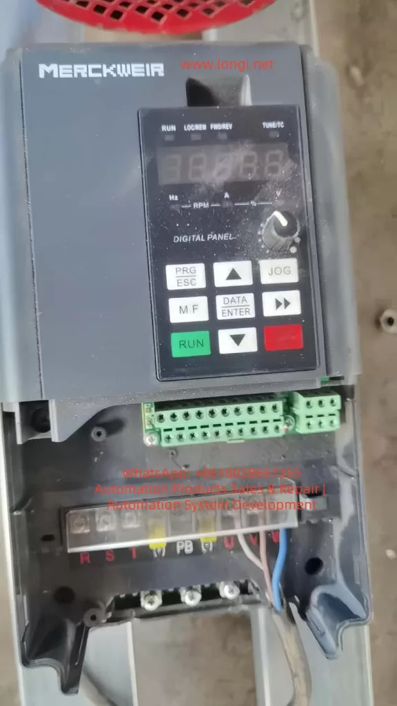
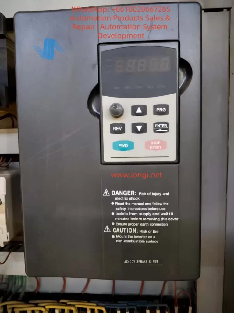
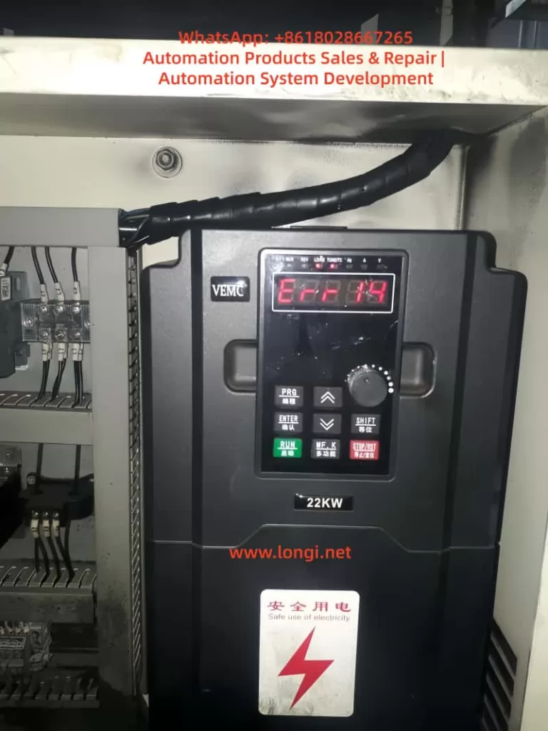
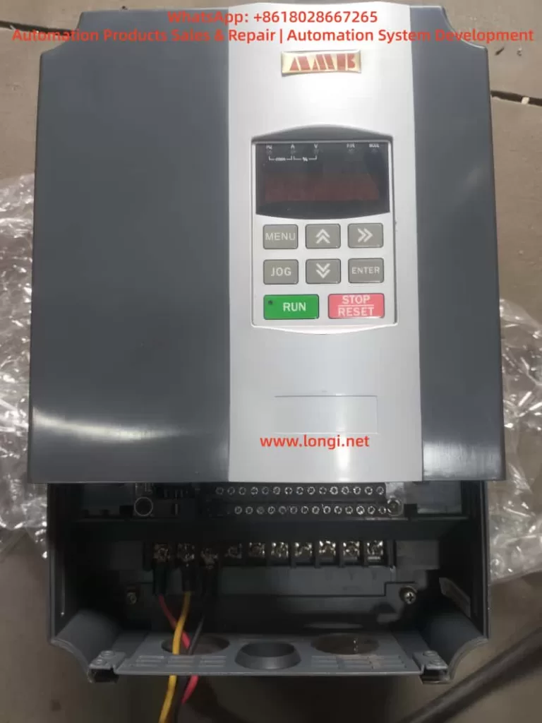
The operation panel of the AMB300 series inverters integrates functional modules such as a five-digit LED digital tube monitor, light-emitting diode (LED) indicators, and operation buttons, providing an intuitive operation interface and rich display information.
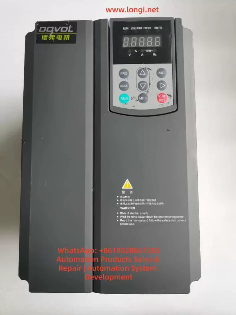
1.2 Functions of Operation Buttons
- RUN Button: Starts the inverter operation.
- STOP/RESET Button: Stops the inverter operation or resets faults.
- Shift Buttons (<< and >>): Used for shifting operations during parameter setting, as well as for switching between operation monitoring and fault monitoring displays.
- Increase (▲) and Decrease (▼) Buttons: Used for increasing or decreasing numerical values during parameter setting.
- OK Button: Confirms parameter settings or enters the next-level menu.
- MENU Button: Programming/exit button, used to enter or exit the programming state.
- JOG Button: Jog operation button, used for jog operation or multifunctional operations.
1.3 Display Information
The operation panel displays function codes, set parameters, operating parameters, and fault information through the LED digital tube. Users can view different display contents using the shift buttons and the increase/decrease buttons.
II. Password Setting and Removal
2.1 Password Setting
To protect the inverter parameters from being arbitrarily modified, users can set a user password.
- Enter Programming State: Press the MENU button to enter the programming state.
- Select Parameter: Use the shift buttons and the increase/decrease buttons to locate the F7.00 (User Password) parameter.
- Set Password: Input the desired password (any number between 0 and 65535) using the increase/decrease buttons.
- Confirm Setting: Press the OK button to save the password setting.
2.2 Password Removal
To remove an already set password, follow these steps:
- Enter Programming State: Press the MENU button to enter the programming state.
- Select Parameter: Use the shift buttons and the increase/decrease buttons to locate the F7.00 (User Password) parameter.
- Clear Password: Set the password value to 0.
- Confirm Setting: Press the OK button to save the setting, and the password protection function will be disabled.
III. Parameter Access Restrictions
To prevent unauthorized personnel from modifying key parameters, the AMB300 series inverters provide a parameter access restriction function.
- Enter Programming State: Press the MENU button to enter the programming state.
- Select Parameter Group: Use the shift buttons and the increase/decrease buttons to locate the parameter group for which access restrictions are to be set.
- Set Access Permissions: Set access permissions (such as read-only or requiring a password for access) through relevant parameters (such as an unspecified parameter beside the F7.01 LCD Display Language Selection, but there is usually a similar function).
- Confirm Setting: Press the OK button to save the setting.
IV. Setting Parameters Back to Factory Defaults
If you need to restore the inverter parameters to their factory default values, follow these steps:
- Enter Programming State: Press the MENU button to enter the programming state.
- Select Restore Factory Defaults Parameter: Use the shift buttons and the increase/decrease buttons to locate the F0.12 (Restore Factory Defaults) parameter.
- Set Restore Option: Set F0.12 to 1 (Restore Factory Defaults) or 2 (Clear Fault Records, depending on the model).
- Confirm Setting: Press the OK button, and the inverter will begin restoring the factory default settings and automatically restart upon completion.
V. External Terminal Forward/Reverse Rotation Control
5.1 Wiring Method
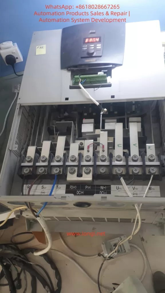
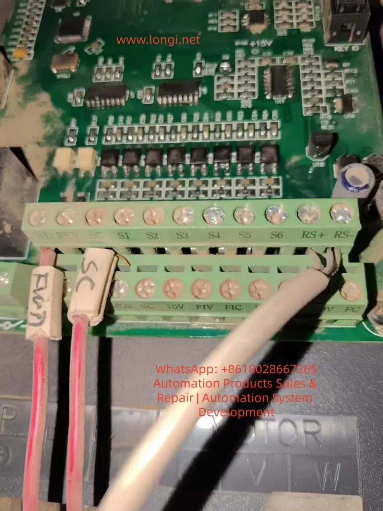
To achieve external terminal forward/reverse rotation control, the forward (FWD) and reverse (REV) control terminals need to be connected to an external control circuit.
- Confirm Terminal Positions: Locate the FWD and REV terminals on the inverter’s control loop terminal block.
- Connect Control Signals: Connect the forward and reverse rotation signals from the external control circuit to the FWD and REV terminals, respectively.
- Connect Common Terminal: Connect the common terminal (COM) of the FWD and REV terminals to the common ground of the external control circuit.
5.2 Parameter Settings
To make the external terminal forward/reverse rotation control effective, the following parameter settings are required:
- Operation Command Selection: Set F0.04 (Operation Command Selection) to 1 (Terminal Command Channel).
- Forward/Reverse Terminal Functions: Ensure that at least one of the X1-X6 multifunctional terminals is set to the forward (FWD) and reverse (REV) functions (set through F1.00-F1.05).
- Other Relevant Parameters: Set parameters such as acceleration time (F0.02) and deceleration time (F0.03) according to actual needs.
VI. External Potentiometer Speed Regulation
6.1 Wiring Method
To achieve external potentiometer speed regulation, the potentiometer needs to be connected to the analog input terminals of the inverter.
- Confirm Terminal Positions: Locate the AI1 (or AI2) and GND terminals on the inverter’s control loop terminal block.
- Connect Potentiometer: Connect the two ends of the potentiometer to the AI1 (or AI2) and GND terminals, respectively, with the middle tap serving as the speed regulation signal input.
- Power Connection: If necessary, provide external power (usually +10V, which can be obtained from the inverter’s control terminal block) for the potentiometer.
6.2 Parameter Settings
To make the external potentiometer speed regulation effective, the following parameter settings are required:
- Frequency Source Selection: Set F0.05 (Frequency Source Selection) to 1 (Analog AI1 Setting) or 2 (Analog AI2 Setting).
- Analog Input Range: Set the lower limit value (F1.09/F1.13) and upper limit value (F1.11/F1.17) of AI1 (or AI2) according to the output range of the potentiometer (usually 0-10V or 0-20mA).
- Other Relevant Parameters: Set parameters such as maximum output frequency (F0.06), upper frequency limit (F0.07), and lower frequency limit (F0.08) according to actual needs.
VII. Fault Codes and Solutions
7.1 Common Fault Codes
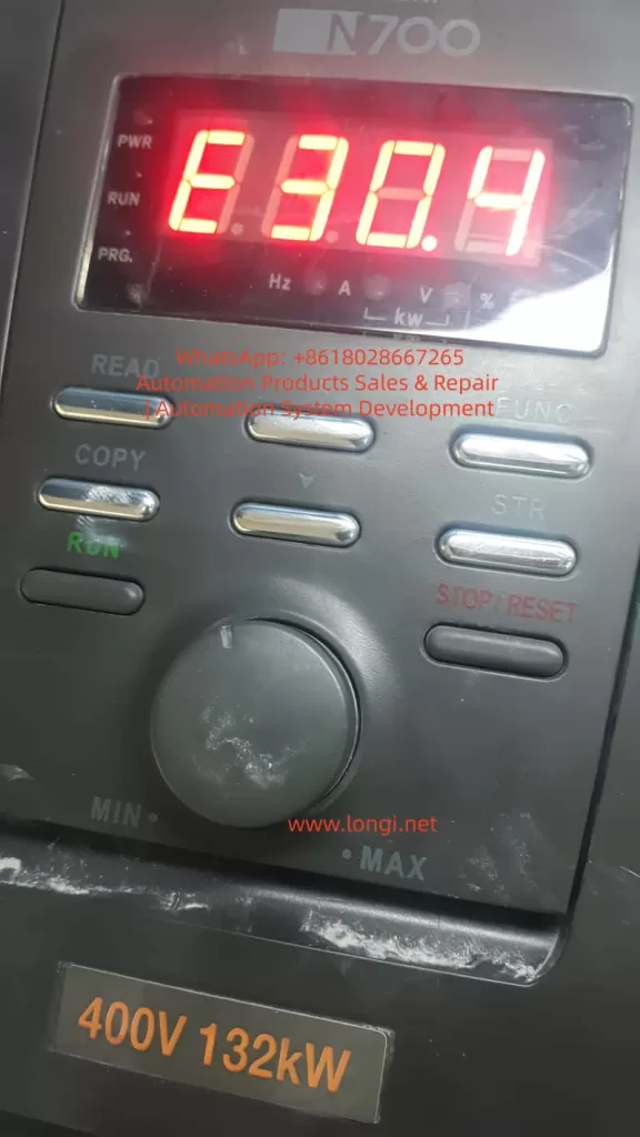
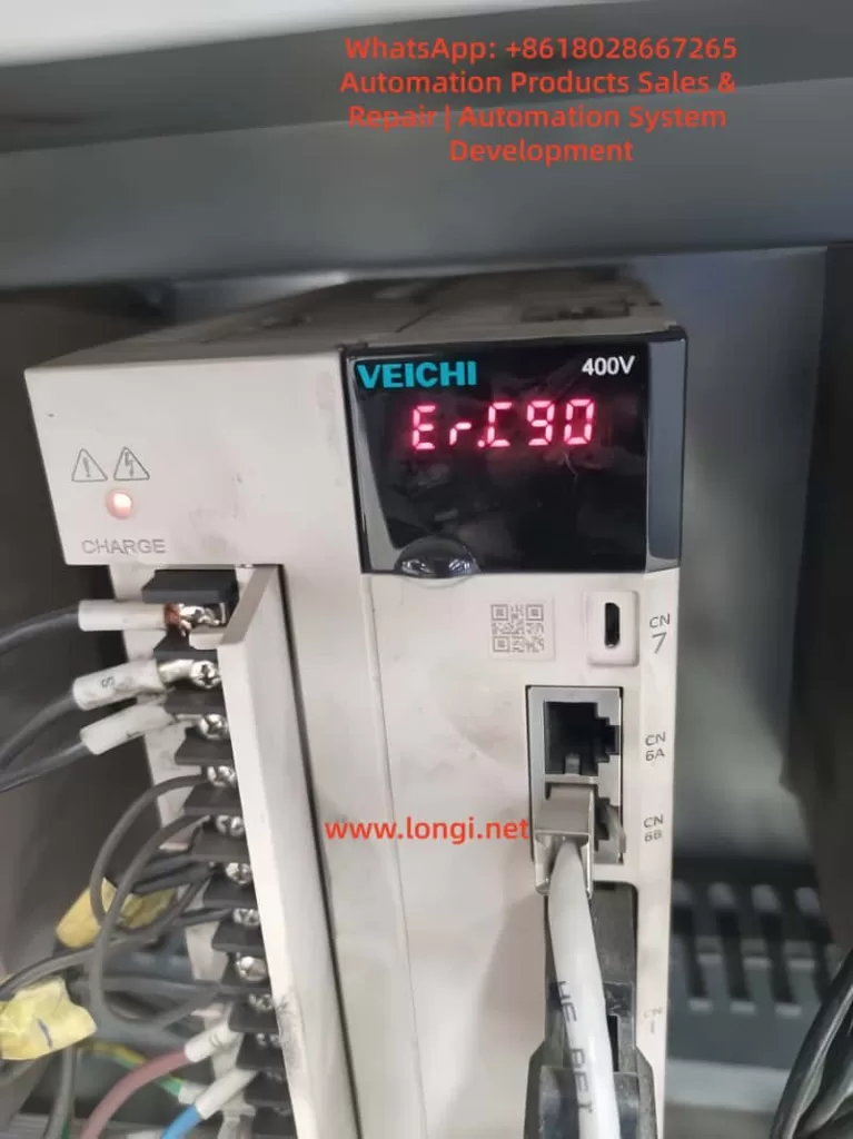
The AMB300 series inverters may encounter various faults during operation. Common fault codes and their causes are as follows:
- E.SC: Drive circuit fault, possibly caused by a short circuit between phases or to ground on the inverter’s three-phase output, a direct connection between the same bridge arms of the power module, or module damage.
- E.OCA: Acceleration overcurrent, possibly caused by a short circuit on the inverter’s output side, excessive load, or too short an acceleration time.
- E.OCd: Deceleration overcurrent, possibly caused by too short a deceleration time or excessive regenerative energy from the motor.
- E.OUA: Acceleration overvoltage, possibly caused by restarting a rotating motor or significant changes in the input power supply.
- E.LU: Undervoltage, possibly caused by a missing phase in the input power supply or significant changes in the input power supply.
- E.OL1: Motor overload, possibly caused by inaccurate motor parameters or motor stalling.
- E.OH1/E.OH2: Module overheating, possibly caused by high ambient temperature, poor ventilation of the inverter, or a faulty cooling fan.
7.2 Solutions
For different fault codes, the following solutions can be adopted:
- E.SC: Check for short circuits on the inverter’s output side and replace damaged power modules.
- E.OCA/E.OCd: Extend the acceleration/deceleration time, check if the load is too heavy, and adjust the torque boost setting value.
- E.OUA: Avoid restarting a stopped motor and check if the input power supply is stable.
- E.LU: Check if the input power supply is normal and ensure there are no missing phases.
- E.OL1: Reset the motor parameters and check if the load is abnormal.
- E.OH1/E.OH2: Improve the ventilation environment, replace the cooling fan, and check the temperature detection circuit.
Conclusion
The AMB300 series of Ampower inverters have been widely used in the field of industrial automation due to their high performance, multifunctionality, and ease of operation. This article has provided a detailed introduction to the operation panel functions, password setting and removal, parameter access restrictions, setting parameters back to factory defaults, as well as how to achieve external terminal forward/reverse rotation control and external potentiometer speed regulation for this series of inverters. Additionally, it has explored common fault codes and their solutions. It is hoped that this article can provide useful reference and guidance for a wide range of users.