Introduction
In modern machining systems, tool setters serve as the critical link between “tool preparation” and “CNC machining.” By precisely measuring tool parameters (length, diameter, position) and transmitting data to CNC systems in real time, they enable automatic tool compensation adjustment—this step directly determines part dimensions, surface quality, and production efficiency. Statistics show that approximately 30% of machining errors stem from tool setting mistakes, making the stability and reliability of tool setters paramount.
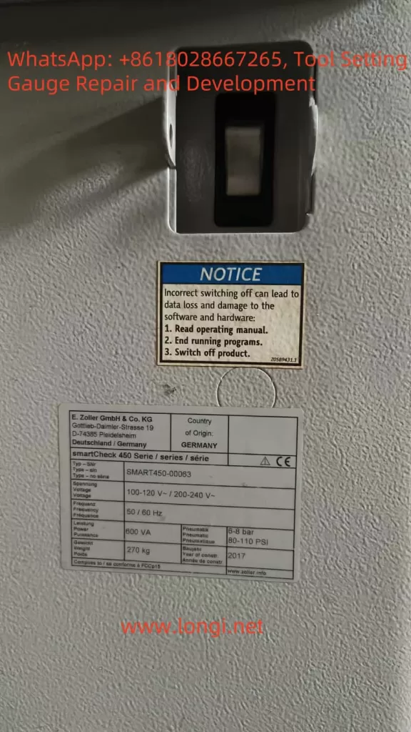
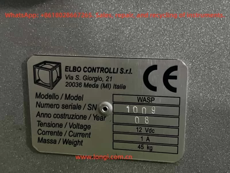
Italian ELBO CONTROLLI S.r.l., a globally renowned manufacturer of industrial measurement equipment, has gained widespread adoption for its WASP series tool setters in turning, milling, grinding, and other processes across automotive, aerospace, and mold industries. Renowned for high precision (±0.001mm), compatibility with mainstream CNC systems (Fanuc, Siemens, Heidenhain), and durability, the WASP series is a cornerstone of high-end manufacturing. However, in long-term industrial use, equipment may experience faults such as coordinate fluctuation, measurement deviation, and communication failure due to improper maintenance, component aging, or operational errors—impacting efficiency and quality.
This article delves into the core principles of tool setters, analyzes the product architecture of the WASP series, and provides a systematic guide to fault diagnosis, troubleshooting, and full-lifecycle maintenance—empowering users to achieve “zero-failure” operation and enhance manufacturing precision.
Chapter 1 Core Principles and Product Architecture of WASP Series
To understand tool setter failures, we first clarify their working logic: a closed-loop process of “measurement-calculation-transmission.”
1.1 Fundamental Working Principle of Tool Setters
The core function of a tool setter is to obtain precise tool position relative to the machine coordinate system. The process involves three steps:
- Tool Positioning: Secure the tool in a dedicated chuck (e.g., ER collet, turning tool holder) to ensure no looseness.
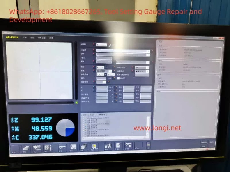
- Measurement Detection: Use an optical measurement head (camera + image recognition algorithm) or contact measurement head (high-precision probe + sensor) to capture tool轮廓 features (e.g., endpoint, diameter) and calculate X (radial) and Z (axial) coordinates.
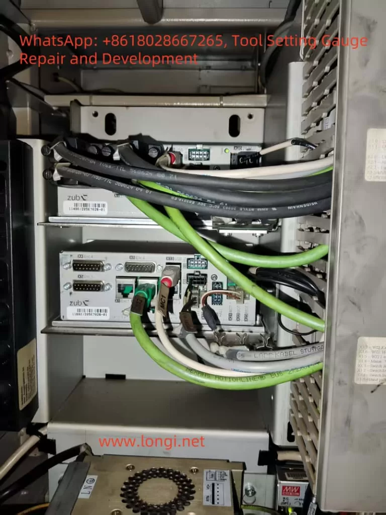
- Data Transmission: Send results to the CNC system via RS232, Ethernet, or fieldbus (e.g., Profibus). The system automatically updates tool length compensation (G43/G44) or radius compensation (G41/G42), enabling seamless “tool setting-machining” integration.
1.2 Product Positioning and Differentiated Features of WASP Series
The WASP series is designed for industrial mass production and includes three models: WASP Touch (entry-level), WASP Plus (mainstream), and WASP Pro (high-end). Key differences lie in functionality and application scenarios:
- WASP Touch: Entry-level with a 7-inch color touchscreen, manual measurement trigger—ideal for small-batch, low-precision parts (e.g., general mechanical components).
- WASP Plus: Mainstream model with automatic measurement (triggers automatically after tool loading), compatibility with 10+ CNC systems—suited for automotive parts, molds, and medium-high precision machining.
- WASP Pro: High-end with multi-axis linkage measurement (X/Z/C-axis synchronization), AI image recognition (automatic tool wear detection), and remote monitoring (cloud-based status tracking)—perfect for aerospace, medical devices, and precision machining.
Shared design advantages:
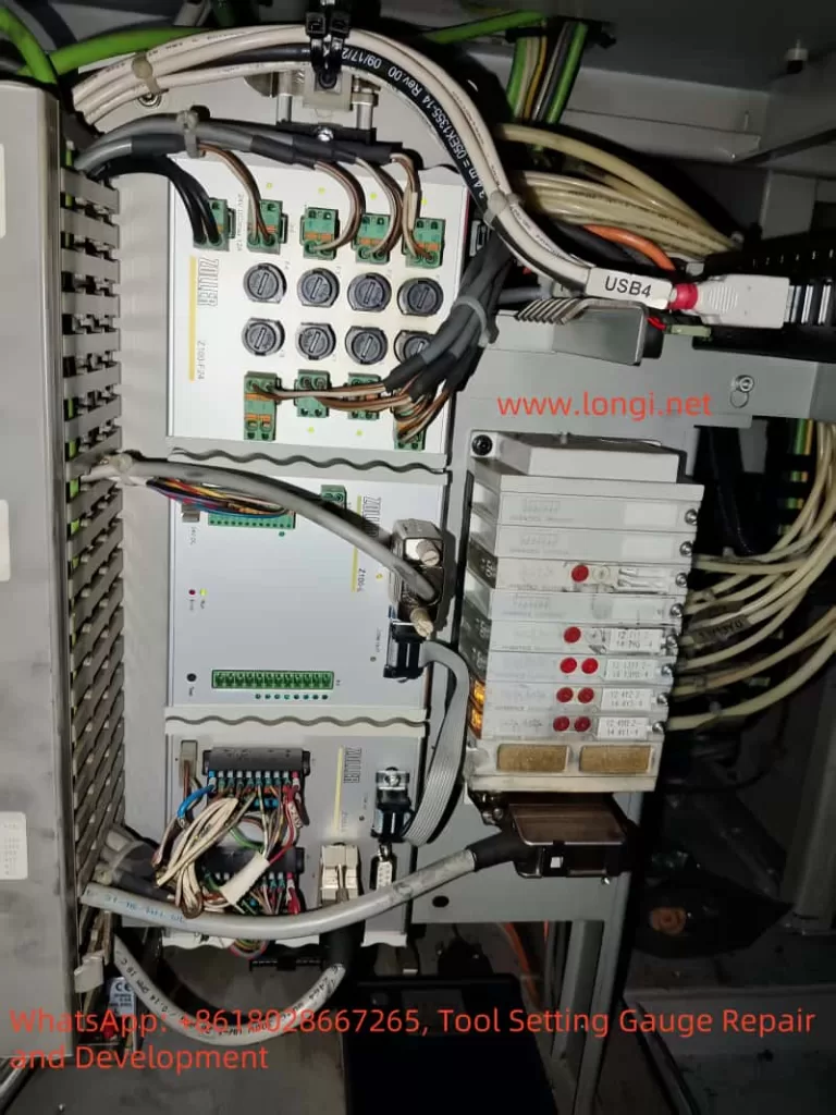
- Modular Structure: Quick-disassembly components (measurement head, control board, guide rail) reduce maintenance time by 50%.
- Anti-Interference Design: Metal-shielded housing + shielded cables resist electromagnetic interference (EMI) from machine tools (e.g., motors, inverters).
- Human-Machine Interaction Optimization: Touchscreen with “tool轮廓 preview” and “measurement history traceability”—operators require no professional training.
Chapter 2 Fault Diagnosis and Troubleshooting for WASP Series
Tool setter failures stem from breaks in the “measurement chain”—any anomaly from “tool clamping” to “data transmission” causes coordinate deviation or function failure. Below are solutions for five high-frequency faults:
2.1 Measurement Accuracy Failure: Coordinate Fluctuation and Poor Repeatability
Symptoms:
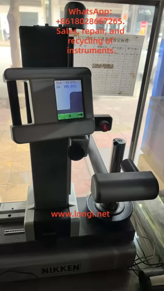
- Single measurement: Coordinates fluctuate (e.g., Xad jumps from 20.061mm to 20.080mm, then back to 20.065mm).
- Multiple measurements of the same tool: Results vary by >0.005mm (e.g., Za = 179.980mm first, 180.020mm second).
Root Causes:
Accuracy failure arises from measurement head contamination or calibration offset:
- Measurement Head Contamination:
Optical heads (lens) or contact heads (probe) are coated with chips, oil, or dust, causing signal collection errors:- Optical heads: Oil scatters light, blurring images and preventing accurate tool edge detection.
- Contact heads: Oxidized or dirty probes increase resistance, delaying or interrupting signals.
- Calibration Failure:
Long-term lack of calibration shifts the coordinate zero point (e.g., Z-axis zero moves due to machine vibration) or uses worn gauge blocks (e.g., a 100mm block wears 0.003mm after 1 year), leading to measurement deviations.
Troubleshooting Steps:
- Step 1: Clean the Measurement Head (80% of accuracy issues stem from this):
- Optical heads: Wipe the lens with a lint-free cloth + isopropyl alcohol (≥99.5%). For stubborn dirt, use lens cleaning paper (avoid scratching the coating).
- Contact heads: Polish the probe with 1000-grit sandpaper to remove oxidation, then wipe with alcohol to ensure a bright surface.
- Step 2: Recalibrate the Equipment:
- Prepare grade 0 standard gauge blocks (e.g., 100mm, 50mm, error ≤0.001mm).
- Enter “Settings” → “Calibration Mode,” place the block on the measurement table, and input its actual size.
- The device adjusts the coordinate system automatically. After calibration, measure the same block 3 times—if results vary by ≤0.002mm, calibration is valid.
2.2 Mechanical Motion Anomaly: Coordinate Jump and Stuttering
Symptoms:
- Sudden large coordinate jumps (e.g., Xad from 20.061mm to 20.100mm).
- “Clicking” sounds or stuttering during mechanical movement; manual pushing requires force.
Root Causes:
Motion anomalies stem from increased transmission system resistance, primarily affecting guide rails, lead screws, and bearings:
- Guide Rail/Lead Screw Jamming:
Chips and oil accumulate in guide rail gaps or lead screw threads, causing “slip” (screw rotates but guide rail does not move), leading to coordinate jumps. - Bearing Lubrication Deficiency:
X/Z-axis bearings (e.g., deep groove ball bearing 608ZZ) wear due to lack of oil, causing “jerky” coordinate changes.
Troubleshooting Steps:
- Clean Transmission Components:
- Power off and remove the device housing. Use a brush + compressed air to clear chips/oil from guide rails.
- Wash the lead screw with kerosene to remove old grease, then dry with a lint-free cloth.
- Apply lithium-based grease (recommended by ELBO) evenly (fill 1/3–1/2 of the guide rail gap).
- Inspect Bearing Condition:
Rotate the bearing manually—if “stuck” or “noisy,” replace it with the same model (align during installation to avoid deformation).
2.3 Communication Failure: Data Not Transmitted to CNC System
Symptoms:
- No “tool setting complete” feedback from the CNC system after measurement.
- Device prompts “communication timeout” or “data error.”
Root Causes:
Communication failure is a signal chain break, often due to:
- Loose Interfaces: RS232/Ethernet ports loosen from vibration or frequent plugging.
- Protocol Mismatch: The tool setter’s protocol (e.g., ELBO custom) does not match the CNC system’s (e.g., Fanuc’s “Tool Setter Protocol”).
- Damaged Cables: Communication cables are crushed by machine tool components, breaking internal wires.
Troubleshooting Steps:
- Check Physical Interfaces:
Plug/unplug communication cables (e.g., RS232 DB9, Ethernet RJ45) to ensure tightness. Use a multimeter to test cable continuity (RS232 pins 2 (TX), 3 (RX), 5 (GND) should conduct). Replace with shielded cables if damaged (shielding layer must be grounded to reduce EMI). - Configure Communication Protocol:
- Enter “Settings” → “Communication Settings” on the tool setter and select the same protocol as the CNC system (e.g., “Fanuc Protocol” for Fanuc).
- Set matching parameters on the CNC system (e.g., baud rate 9600, no parity, 8 data bits).
2.4 Power Interference: Frequent Reboots or Coordinate Chaos
Symptoms:
- Frequent automatic reboots or “low voltage” prompts on the screen.
- Unpredictable coordinate fluctuations (e.g., Xad jumps from 20.061mm to 19.950mm, then to 20.100mm).
Root Causes:
Power anomalies destabilize the control board:
- Voltage Fluctuation: Unstable industrial power (e.g., 12Vdc output varies by >±5%) causes CPU/memory errors.
- Electromagnetic Interference (EMI): Communication cables near motors/inverters pick up noise, “contaminating” coordinate data.
Troubleshooting Steps:
- Stabilize Power Supply:
Use a regulated power supply (e.g., 12Vdc/5A switching power supply, output variation ≤±1%) instead of direct industrial grid connection. Test output voltage with a multimeter regularly. - Eliminate EMI:
- Keep communication cables ≥1 meter away from motors/inverters.
- Ground the device’s grounding terminal (resistance ≤4Ω) to divert interference to earth.
- Add ferrite beads to communication cables for severe interference.
2.5 Tool/Workpiece Clamping Issues: Measurement vs. Actual Value Mismatch
Symptoms:
- Machined part dimensions deviate significantly (e.g., part thickness should be 20mm but is 19.8mm).
- Tool shaking during measurement; “blurred” tool轮廓 on the screen.
Root Causes:
Clamping issues disconnect “measurement value from actual value”:
- Loose Tool Clamping: Using non-dedicated chucks (e.g., ordinary chucks instead of ER collets) causes tool shaking, leading to inaccurate轮廓 capture.
- Inaccurate Workpiece Positioning: The workpiece is not placed on the tool setter’s datum plane (e.g., flat locating block), causing incorrect tool-workpiece coordinates.
Troubleshooting Steps:
- Standardize Tool Clamping:
Use appropriate chucks (e.g., ER32 for milling cutters, special holders for turning tools) and tighten screws to the specified torque (e.g., 15–20N·m for ER collets). Check for looseness by hand. - Calibrate Workpiece Position:
Place the workpiece on the tool setter’s datum plane and secure it with pressure plates. Use the CNC system’s “workpiece coordinate system” (e.g., Fanuc G54–G59) and a dial indicator to verify workpiece-tool setter coordinate alignment.

Chapter 3 Full-Lifecycle Maintenance for WASP Series
Tool setter precision is “maintained, not fixed.” Daily care + periodic maintenance reduces failure rates by 70% and extends service life to 5–8 years.
3.1 Daily Maintenance (Per Shift)
- Cleaning: Wipe the device (screen, measurement head, guide rail) with a lint-free cloth to remove dust/oil.
- Inspection: Check communication/power cables for tightness and guide rails for chips before startup.
- Documentation: Fill out the Equipment Maintenance Log to record shift status (e.g., “measurement head cleaned,” “guide rail lubricated”).
3.2 Periodic Maintenance (Quarterly/Semi-Annually)
- Calibration: Calibrate with standard gauge blocks quarterly (monthly for precision parts).
- Lubrication: Clean guide rails/lead screws semi-annually and reapply grease (use ELBO-recommended grease).
- Component Inspection: Annually check measurement heads, bearings, and control boards—replace scratched lenses, noisy bearings, or bulging capacitors.
3.3 Long-Term Storage (Shutdown >1 Month)
- Environment: Store in a dry, ventilated room (10–30°C, humidity ≤70%) away from direct sunlight.
- Protection: Cover with a dust cover to prevent dust ingress.
- Battery Maintenance: Replace the built-in CMOS battery every 2 years to avoid leakage and control board damage.
Chapter 4 Application Case: Troubleshooting in an Auto Parts Factory
Case Background:
A factory using a 2018 WASP Plus for engine block milling faced Z-axis coordinate fluctuation (0.05mm variation in repeated measurements), causing “cylinder bore depth” out of tolerance (±0.02mm) and increasing defect rates from 1% to 5%.
Troubleshooting & Resolution:
- Step 1: Clean the Measurement Head:
Removed the head cover and found oil on the optical lens (from coolant splashes). After wiping with isopropyl alcohol, fluctuation reduced to 0.02mm—still non-compliant. - Step 2: Calibrate:
Used a 100mm gauge block and found the device showed 100.03mm (actual: 100.00mm). Adjusted the “Z-axis offset” from +0.03mm to 0, restoring accuracy. - Step 3: Clean Guide Rails:
Removed the housing and found aluminum chips on the Z-axis guide rail. Cleaned and lubricated—mechanical movement became smooth. - Validation:
Re-measured the same tool: Za stabilized at 180.00mm ±0.002mm. Defect rate dropped to <0.5%, resuming normal production.
Conclusion
The ELBO CONTROLLI WASP series is a “guardian of precision” in industrial machining. Most failures stem from neglect of details—a single uncleaned measurement head or unlubricated guide rail can compromise accuracy. By following the fault diagnosis logic and maintenance plan in this article, users can quickly resolve issues and maintain optimal performance through full-lifecycle care.
As Industry 4.0 advances, tool setters will evolve toward intelligence (AI tool wear detection) and automation (robot integration for automatic tool changing/setting). However, “precision” remains the core value—and proper use and maintenance are the foundation of this value.
For manufacturers, “zero-failure” tool setter operation enhances efficiency, reduces defects, and lays the groundwork for “smart manufacturing”—the very mission of the ELBO WASP series.