Introduction
In the development and production of electronic products, Electromagnetic Compatibility (EMC) testing is a crucial step to ensure product quality and reliability. Electrostatic Discharge (ESD) immunity testing, as an important part of EMC testing, is used to evaluate the anti-interference ability of electronic products when subjected to electrostatic discharges. The Noisken Electrostatic Discharge Simulator ESS-B3011A series is a high-performance, multi-functional ESD testing device widely used for ESD testing of various electronic equipment. This guide will provide a detailed introduction to the usage of the ESS-B3011A series simulator, helping users better understand and operate the equipment.
1. Product Overview
1.1 Product Introduction
The Noisken Electrostatic Discharge Simulator ESS-B3011A series is a computer-controlled electrostatic discharge generator that complies with international standards such as IEC 61000-4-2 and ISO 10605. It can simulate electrostatic discharge phenomena generated when a human body or object comes into contact with or approaches electronic equipment. By connecting different electrostatic discharge guns, this device can achieve various testing modes, including contact discharge and air discharge, helping users comprehensively evaluate the ESD immunity of electronic products.
1.2 Key Features
- High Compatibility: Supports multiple electrostatic discharge guns, such as GT-30R/GT-30RA, TC-815R, TC-815S, etc., meeting different testing requirements.
- Standardized Testing: Complies with international standards like IEC 61000-4-2 and ISO 10605, ensuring the authority and comparability of test results.
- Easy Operation: The inclined front panel design facilitates operation, with well-arranged knobs and switches for convenient setting of test conditions.
- Multi-functional Testing: Provides one-key setting of IEC standard test levels, discharge detection functions, pre-check functions, etc., supporting multiple testing modes and trigger methods.
- Safe and Reliable: Equipped with multiple safety protection mechanisms to ensure the safety of equipment and personnel during the testing process.
2. Safety Precautions
2.1 User Restrictions
The ESS-B3011A series simulator is only intended for use by professional technicians who have received EMC testing training.
Untrained personnel operating this device may lead to serious consequences such as electric shocks or fires.
Individuals with electronic medical devices (such as pacemakers) are not allowed to use this device or enter the testing site.
2.2 Usage Environment
Do not use the ESS-B3011A series simulator in places where smoking is prohibited or where there is a risk of explosion.
Ensure good ventilation at the testing site and avoid running the device for extended periods in high-temperature, high-humidity, or corrosive environments.
2.3 Electrical Safety
Before use, check whether the device’s power cord is intact and properly grounded.
Do not arbitrarily replace the device’s power plug or use non-standard power cords.
When connecting or disconnecting device cables, ensure that the device is turned off and the power plug is disconnected.
2.4 Operational Safety
During operation, do not touch the discharge tip of the discharge gun.
The discharge gun must not be aimed at personnel or flammable items for discharge testing.
If any abnormalities (such as smoking or strange odors) are detected during the testing process, immediately stop the test, disconnect the power plug, and contact professionals for maintenance.
3. Detailed Explanation of Product Functions and Features
3.1 Compatible Standards and Discharge Guns
The ESS-B3011A series simulator supports multiple electrostatic discharge guns, each of which complies with specific international standards.
Users can select the appropriate discharge gun according to their testing needs.
- GT-30R/GT-30RA Discharge Guns: Comply with IEC 61000-4-2 and ISO 10605 standards and are suitable for most ESD testing scenarios.
- TC-815R/TC-815S Discharge Guns: These are existing discharge guns from Noisken that can also be used for testing with the ESS-B3011A series simulator.
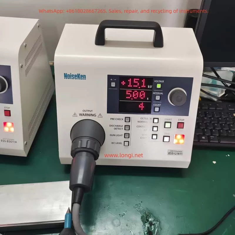
3.2 Operation Panel and Switches
- Display Screen: Displays information such as current test conditions, test modes, and test results.
- Knob: Used to adjust the values of test parameters. Rotating the knob changes the parameter value, and pressing the knob switches the currently edited digit.
- Function Switches: Include the power switch, test mode selection switch, trigger method selection switch, etc. Users can select the appropriate test mode and trigger method through these switches.
3.3 Convenient Functions
- One-key Setting of IEC Standard Test Levels: By pressing the [IEC LEVEL] key, users can quickly set the test voltage levels that comply with the IEC 61000-4-2 standard.
- Discharge Detection Function: In air discharge mode, the device can detect actual discharge situations and notify the user. This function helps users confirm whether the discharge has occurred successfully.
- Pre-check Function: Performs a pre-check of the internal high-voltage power supply of the device before testing to ensure normal output voltage. This function helps reduce the failure rate during the testing process.
3.4 Radiation Level Modes
- Extra Mode (EXTRA): Reduces the radiation noise generated by the discharge gun, suitable for testing scenarios sensitive to radiation noise.
- Normal Mode (NORMAL): The radiation noise level is similar to that of previous models, suitable for general testing scenarios.
Users can switch between radiation level modes using the [EXTRA / NORMAL] switch on the operation panel.

4. Basic Testing Process
4.1 Device Connection
- Connect the AC Power Cord: Insert the AC power cord provided with the device into the AC inlet interface on the rear of the device and the other end into a power socket with a protective grounding terminal.
- Connect the Discharge Gun: Align the high-voltage input connector of the discharge gun with the high-voltage output connector on the device and insert it. Then, rotate the safety ring on the discharge gun clockwise to secure the connector.
4.2 Test Planning
Determine the test mode (contact discharge or air discharge) and test conditions (polarity, voltage, discharge interval, and number of discharges) according to testing requirements.
- Contact Discharge Testing: Use a conical discharge tip and place the tip in contact with the test point of the Equipment Under Test (EUT) for discharge testing. It is suitable for evaluating the ESD immunity of the EUT’s housing or coupling plane.
- Air Discharge Testing: Use a circular discharge tip, move the discharge gun a certain distance away from the EUT, and then quickly approach and make contact with the EUT for discharge testing. It is suitable for evaluating the ESD immunity of the EUT’s insulating coating or insulating housing.
4.3 Basic Settings
- Set Polarity: Select the polarity (positive or negative) of the output voltage by pressing the [+/−] switch on the operation panel.
- Set Voltage, Discharge Interval, and Number of Discharges: Press the corresponding switches ([VOLTAGE], [INTERVAL], [COUNT]) and rotate the knob to set the values of these parameters. The voltage setting range is from 0.20 kV to 30.0 kV, the discharge interval setting range is from 0.05 seconds to 99.9 seconds, and the number of discharges setting range is from 1 to 999 times or continuous discharge.
4.4 Execute the Test
- Start the Test: Press the [START] switch on the operation panel to start the test. The device will output high voltage and wait for a trigger signal for discharge testing.
- Input Trigger Signal: Select the appropriate trigger method (gun trigger or controller trigger) according to the test mode. In contact discharge mode, press the trigger switch on the discharge gun for discharge; in air discharge mode, press the [TRIG] switch on the main unit for discharge.
- Observe Test Results: During the testing process, observe the test results and the status of the warning lights on the display screen. If any abnormalities (such as discharge failure or device alarms) are found, immediately stop the test and check the device status.
4.5 End the Test
- Stop the Test: Press the [STOP] switch on the operation panel to stop the test. The device will turn off the high-voltage power supply output and stop the discharge testing.
- Disconnect Device Connections: After the test is completed, first disconnect the connection between the discharge gun and the EUT, and then disconnect the AC power cord. Ensure that the device is turned off before performing these operations.
5. Advanced Functions and Settings
5.1 Automatic Identification of CR Units and Discharge Cups
The ESS-B3011A series simulator has the function of automatically identifying whether the types of CR units and discharge cups and their combinations comply with standards. When the user replaces the CR unit or discharge cup and restarts the device, the device will automatically perform identification and display the compliance standards (such as IEC 61000-4-2 Ed1.2 & Ed2.0, ISO 10605 2nd Ed., etc.). This function helps users ensure the compliance of test conditions.
5.2 Sensitivity Setting of Discharge Detection Function
In air discharge mode, the discharge detection function may fail to detect the discharge due to factors such as the impedance of the discharge channel and the charged state of the tested object. At this time, users can improve the detection success rate by adjusting the sensitivity of the discharge detection function. Press and hold the [DISCHARGE DETECT] switch for more than one second to enter the sensitivity setting mode, and then rotate the knob to select low (Lo), medium (Mid), or high (Hi) sensitivity levels.
5.3 Pre-check Function
The pre-check function is used to check whether the output voltage of the internal high-voltage power supply of the device is normal. Performing a pre-check before testing ensures that the device is in good condition and reduces the failure rate during the testing process. Place the discharge gun on an insulator and away from the device body, press the [PRE CHECK] switch to display [Chk Rdy] (check ready), and then press the [START] switch to start the pre-check. The pre-check process takes about 20 seconds. After completion, the display screen will show [Chk +OK –OK] (check successful) or error information.
6. Maintenance and Troubleshooting
6.1 Daily Maintenance
- Clean the Device: Regularly use a dry cloth to wipe off dust and dirt on the device housing and operation panel. Avoid using chemical cleaners or solvents to prevent damage to the device’s surface coating or markings.
- Check Power Cords and Connectors: Regularly check whether the power cords and connectors are intact and properly grounded. If any damage or looseness is found, replace or tighten them in a timely manner.
- Storage Environment: Store the device in a dry, well-ventilated environment without corrosive gases. Avoid exposing the device to high temperatures, high humidity, or direct sunlight for extended periods.
6.2 Troubleshooting
- ERROR 1: Discharge Gun Interlock Error
- Cause: There is an interlock signal on the high-voltage output connector.
- Solution: Press the [STOP] switch to clear the error and correctly connect the high-voltage connector of the discharge gun.
- ERROR 3: Trigger Error
- Cause: The trigger switch is stuck in the input position.
- Solution: Press the [STOP] switch to clear the error and stop the trigger switch from remaining in the input position. Try changing the trigger selection (e.g., from gun trigger to controller trigger).
- ERROR 6: High-voltage Power Supply Output Error
- Cause: The output of the high-voltage power supply cannot be confirmed.
- Solution: Press the [STOP] switch to clear the error and check whether the device is faulty. If the problem persists, contact professionals for maintenance.
- ERROR 8: CR Unit or Discharge Cup Identification Error
- Cause: The CR unit or discharge cup is not connected, or the GT-30R/GT-30RA discharge gun is faulty.
- Solution: Press the [STOP] switch to clear the error and correctly connect the CR unit and discharge cup. If the problem persists, check whether the CR unit and discharge cup are faulty and contact professionals for maintenance.
7. Specifications and Parameters
7.1 Main Parameters
- Output Polarity: Positive or negative
- Output Voltage: 0.20 kV to 30.0 kV (maximum 30.5 kV), with step settings varying according to the voltage range (0.20 kV to 10.00 kV: 0.01 kV step; 10.0 kV to 30.0 kV: 0.1 kV step)
- Repetition Period: 0.05 seconds to 99.9 seconds (±10%), manually settable (0.05 seconds to 9.99 seconds: 0.01 second step; 10.0 seconds to 99.9 seconds: 0.1 second step)
- Number of Discharges: 1 to 999 times (step of 1), or continuous discharge setting (set by further reducing the lower limit [1], displayed as [Cnt])
- Electrostatic Discharge Modes: Contact discharge mode or air discharge mode
- Radiation Level Modes: Extra mode or normal mode
- Trigger Modes: Gun trigger or controller trigger
7.2 Recommended Discharge Guns
- GT-30R/GT-30RA
- TC-815R
- TC-815S
- TC-815-330/2K
- TC-815S-330/2K
7.3 Electrical Parameters
- Charging Resistance: 10 MΩ
- Power Supply: AC100 V to AC240 V (±10%), 50 Hz/60 Hz
- Power Consumption: 75 VA
- Operating Temperature Range: +15°C to +35°C
- Operating Humidity Range: 25% RH to 75% RH (no condensation)
- Storage Temperature Range: -10°C to +50°C
- Storage Humidity Range: 0% RH to 85% RH (no condensation)
- External Dimensions: (Width) 270 mm x (Height) 263 mm x (Depth) 200 mm
- Weight: Approximately 4.6 kg
8. Warranty and Maintenance Services
8.1 Warranty Period
The Noisken Electrostatic Discharge Simulator ESS-B3011A series comes with a one-year warranty service from the date of delivery. During the warranty period, if the device fails due to non-human damage, Noise Laboratory Co., Ltd. will provide free repair or replacement services.
8.2 Maintenance Services
Noise Laboratory Co., Ltd. offers professional technical maintenance services, including fault repair, component replacement, and internal adjustments. Users can contact the nearest distributor/agent or Noise Laboratory technical support for assistance.