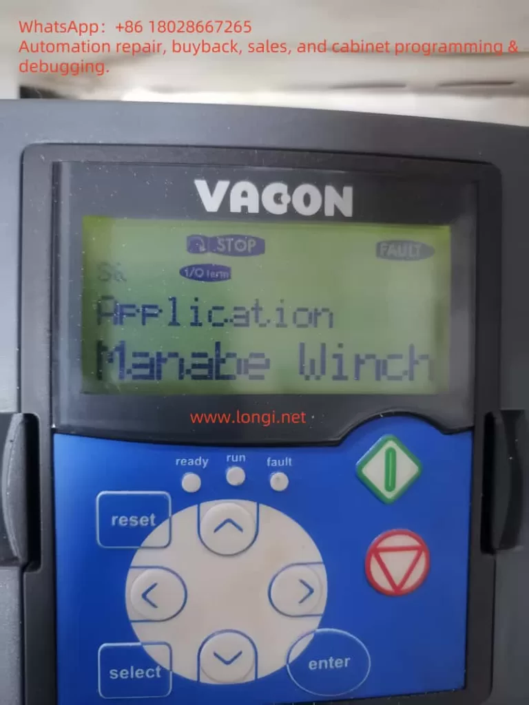
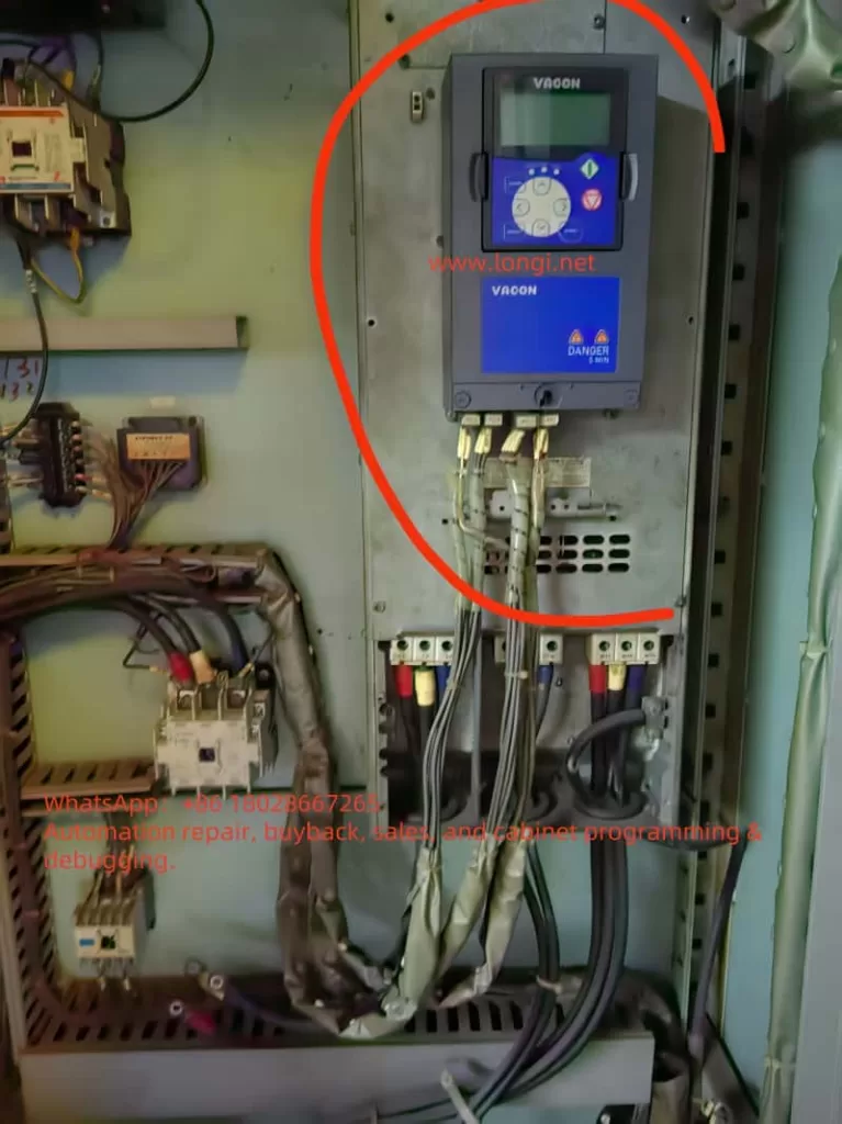
According to the “Vacon NXP Programming Manual” (APFIFF08 ADVANCE), to configure the Vacon NXP inverter for use with a general asynchronous motor and employ a simple V/F (Voltage/Frequency) control mode, key parameters and steps must be set. These parameters primarily focus on motor control mode, basic motor parameters, and V/F control settings. Below is a detailed guide:

1. Set Motor Control Mode to V/F Control
According to Page 143 of the manual, set the motor control mode to V/F control.
- Parameter: P2.8.1 Motor Control Mode (Motor Ctrl Mode, ID600)
- Path: Control Panel Menu M2 -> G2.8.1
- Setting Value: 0 (“Frequency Control”, indicating V/F control mode)
- Explanation: Selecting V/F control mode allows the inverter to control the motor through a fixed ratio of voltage to frequency, without using closed-loop control (such as speed or torque control).
2. Set Basic Motor Parameters
To ensure proper motor operation in V/F control mode, correctly set the motor’s rated parameters, which are typically found on the motor nameplate. The following parameters are described on Pages 63-65 of the manual:
- P2.1.1 Motor Rated Voltage (Nominal Voltage, ID110)
- Path: Control Panel Menu M2 -> G2.1
- Setting Value: According to the rated voltage on the motor nameplate (e.g., 380V, 400V, etc.)
- Explanation: Set the motor’s rated voltage to ensure the inverter outputs the correct voltage.
- P2.1.2 Motor Rated Frequency (Nominal Frequency, ID111)
- Path: Control Panel Menu M2 -> G2.1
- Setting Value: According to the rated frequency on the motor nameplate (e.g., 50Hz or 60Hz)
- Explanation: Set the motor’s rated operating frequency.
- P2.1.3 Motor Rated Speed (Nominal Speed, ID112)
- Path: Control Panel Menu M2 -> G2.1
- Setting Value: According to the rated speed on the motor nameplate (e.g., 1470 rpm, etc.)
- Explanation: Used to calculate the motor’s pole pairs and slip.
- P2.1.4 Motor Rated Current (Nominal Current, ID113)
- Path: Control Panel Menu M2 -> G2.1
- Setting Value: According to the rated current on the motor nameplate (e.g., 10A, 20A, etc.)
- Explanation: Ensure the inverter does not operate overloaded.
- P2.1.5 Motor Power Factor (Cos Phi, ID120)
- Path: Control Panel Menu M2 -> G2.1
- Setting Value: According to the power factor on the motor nameplate (e.g., 0.85)
- Explanation: Used to optimize motor efficiency calculations.
- P2.1.11 Magnetizing Current (Magnetizing Current, ID612) (Optional)
- Path: Control Panel Menu M2 -> G2.1
- Setting Value: According to the magnetizing current on the motor nameplate (if provided), or automatically identified through “ID No Run” (see Page 158).
- Explanation: If unsure, run “ID No Run” (without rotating the motor) to automatically identify the magnetizing current.
3. Set V/F Curve Parameters
The V/F control mode requires defining the relationship curve between voltage and frequency to ensure the motor receives the appropriate voltage at different frequencies. These parameters are described in detail on Page 144 of the manual:
- P2.8.1.1 V/F Curve Type (V/f Curve, ID108)
- Path: Control Panel Menu M2 -> G2.8.1
- Setting Value: 0 (“Linear”, linear V/F curve, suitable for general asynchronous motors)
- Explanation: The linear V/F curve is the simplest control method, suitable for most general asynchronous motor applications.
- P2.8.1.2 Field Weakening Point (Field Weakening Point, ID602)
- Path: Control Panel Menu M2 -> G2.8.1
- Setting Value: Typically set to the motor’s rated frequency (e.g., 50Hz)
- Explanation: The field weakening point defines the frequency at which the motor enters the field weakening region, usually consistent with the rated frequency.
- P2.8.1.3 Voltage at Field Weakening Point (Voltage at Field Weakening Point, ID603)
- Path: Control Panel Menu M2 -> G2.8.1
- Setting Value: Typically set to 100% (i.e., the motor’s rated voltage)
- Explanation: Ensure the motor receives the rated voltage at the field weakening point.
- P2.8.1.4 V/F Midpoint Frequency (V/f Midpoint Frequency, ID604) (Optional)
- Path: Control Panel Menu M2 -> G2.8.1
- Setting Value: Typically set to half of the rated frequency (e.g., 25Hz)
- Explanation: Used to optimize the V/F curve during low-frequency operation, usually not requiring adjustment.
- P2.8.1.5 V/F Midpoint Voltage (V/f Midpoint Voltage, ID605) (Optional)
- Path: Control Panel Menu M2 -> G2.8.1
- Setting Value: Typically set to the percentage of voltage at the midpoint frequency (e.g., 50%)
- Explanation: Used with the midpoint frequency to define a non-linear V/F curve; the default value can be maintained for general applications.
4. Set Frequency Range
According to Pages 10 and 130 of the manual, set the range of the output frequency:
- P2.1.6 Minimum Frequency (Minimum Frequency, ID101)
- Path: Control Panel Menu M2 -> G2.1
- Setting Value: Typically set to 0 Hz or the lowest frequency required by the application (e.g., 5 Hz)
- Explanation: Defines the lowest frequency output by the inverter.
- P2.1.7 Maximum Frequency (Maximum Frequency, ID102)
- Path: Control Panel Menu M2 -> G2.1
- Setting Value: Set according to application requirements (e.g., 50Hz, 60Hz, or higher, up to a maximum of 599Hz)
- Explanation: Defines the highest frequency output by the inverter, ensuring it does not exceed the motor’s design range.
- P2.6.4.1 Negative Frequency Limit (Negative Frequency Limit, ID1286) (Optional)
- Path: Control Panel Menu M2 -> G2.6.4
- Setting Value: If reverse operation is not required, set to 0 Hz
- Explanation: Limits the frequency at which the motor can operate in reverse; typically not required for general asynchronous motor applications.

5. Set Acceleration and Deceleration Times
Acceleration and deceleration times affect the smoothness of motor startup and shutdown. These parameters are described on Pages 90-91 of the manual:
- P2.3.3 Acceleration Time 1 (Acceleration Time 1, ID103)
- Path: Control Panel Menu M2 -> G2.3
- Setting Value: Set according to application requirements (e.g., 5 seconds, 10 seconds, etc.)
- Explanation: Defines the time required to accelerate from 0 Hz to the maximum frequency.
- P2.3.4 Deceleration Time 1 (Deceleration Time 1, ID104)
- Path: Control Panel Menu M2 -> G2.3
- Setting Value: Set according to application requirements (e.g., 5 seconds, 10 seconds, etc.)
- Explanation: Defines the time required to decelerate from the maximum frequency to 0 Hz.
6. Input Signal Settings (Startup/Stop and Frequency Reference)
V/F control typically requires defining the sources of startup/stop signals and frequency reference signals. The following parameters are described on Pages 94-97 of the manual:
- P2.4.1.1 Startup/Stop Logic (Start/Stop Logic, ID300)
- Path: Control Panel Menu M2 -> G2.4.1
- Setting Value: 0 (“Start/Stop”, simple two-wire control, closed to start, open to stop)
- Explanation: Select simple startup/stop logic suitable for general applications.
- P2.2.2 I/O Frequency Reference Selection 1 (I/O Reference Selection 1, ID117)
- Path: Control Panel Menu M2 -> G2.2
- Setting Value: 0 (“Analogue Input 1”, analog input 1) or 3 (“Keypad”, control panel)
- Explanation: Select the source of the frequency reference, such as through an external analog signal (0-10V or 4-20mA) or the control panel.
- P2.4.3.1 Analog Input 1 Signal Selection (AI1 Signal Selection, ID377)
- Path: Control Panel Menu M2 -> G2.4.3
- Setting Value: Select according to actual wiring (e.g., “AI1” for analog input 1)
- Explanation: If using an external analog signal to control the frequency, configure the correct input channel.
7. Run Identification (Optional)
To optimize V/F control performance, it is recommended to run a motor parameter identification once. According to Page 158 of the manual:
- P2.8.8.1 Identification (Identification, ID631)
- Path: Control Panel Menu M2 -> G2.8.8
- Setting Value: 1 (“ID No Run”, identification without rotating the motor)
- Explanation: Run “ID No Run” to automatically identify motor parameters (such as magnetizing current) without rotating the motor, suitable for initial setup.
8. Inspection and Verification
- Check Wiring: Ensure the motor is wired correctly and control signals (such as startup/stop and frequency reference) are connected to the correct terminals (refer to the Control I/O section on Page 11 of the manual).
- Monitor Values: Check output frequency (V1.1, ID1), motor current (V1.23.1, ID1113), etc., in the control panel menu M1 to ensure normal operation (refer to Pages 16-19 of the manual).
- Fault Checking: If a fault occurs (such as overcurrent F1, undervoltage F9, etc.), refer to the fault code table on Pages 210-221 of the manual for troubleshooting.
9. Summary
Below is the minimum parameter set for configuring the V/F control mode for a general asynchronous motor:
- P2.8.1 Motor Control Mode: 0 (Frequency Control)
- P2.1.1 Motor Rated Voltage: Set according to the nameplate (e.g., 380V)
- P2.1.2 Motor Rated Frequency: Set according to the nameplate (e.g., 50Hz)
- P2.1.3 Motor Rated Speed: Set according to the nameplate (e.g., 1470 rpm)
- P2.1.4 Motor Rated Current: Set according to the nameplate (e.g., 10A)
- P2.1.5 Motor Power Factor: Set according to the nameplate (e.g., 0.85)
- P2.8.1.1 V/F Curve Type: 0 (Linear)
- P2.8.1.2 Field Weakening Point: Rated frequency (e.g., 50Hz)
- P2.8.1.3 Voltage at Field Weakening Point: 100% (rated voltage)
- P2.1.6 Minimum Frequency: 0 Hz or application requirements
- P2.1.7 Maximum Frequency: 50Hz or application requirements
- P2.3.3 Acceleration Time 1: e.g., 5 seconds
- P2.3.4 Deceleration Time 1: e.g., 5 seconds
- P2.4.1.1 Startup/Stop Logic: 0 (Start/Stop)
- P2.2.2 I/O Frequency Reference Selection 1: 0 (Analogue Input 1) or 3 (Keypad)
It is recommended to run “ID No Run” identification (P2.8.8.1 = 1) after setting up to optimize motor parameters. If further adjustments are needed (such as low-speed torque compensation or prohibited frequencies), refer to Page 85 (Prohibited Frequencies) or Page 144 (U/f Settings) of the manual.
