Posted on Leave a comment

Troubleshooting and Resolving the A.43 Fault in ZSMC K-Series Servo Drives

Introduction

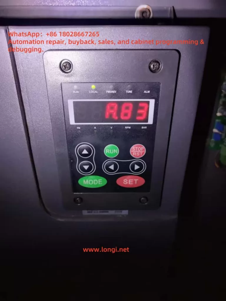
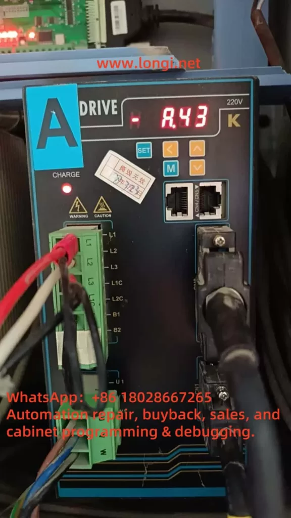
Servo drives are the backbone of precision control in industrial automation, powering applications ranging from CNC machining to robotic assembly lines. The ZSMC K-Series servo drive, renowned for its reliability and efficiency, is no exception. However, even the most robust systems can encounter faults that disrupt operations. One such issue, the A.43 fault, has been reported by a user, with a screenshot showing the fault code displayed on the servo drive. This article delves into the A.43 fault—identified as a “Bus-type encoder cumulative count error”—to provide a comprehensive, step-by-step guide for troubleshooting and resolving it. Drawing from the official user manual (“ZSMC Servo K-Series User Manual Complete Version.pdf,” 2017 Engineering Version V3.0), this guide aims to equip technicians and engineers with the knowledge to address this fault effectively, minimizing downtime and ensuring system reliability.

A.43

Understanding the A.43 Fault

The A.43 fault is explicitly defined in the ZSMC K-Series servo drive manual under “Appendix C: Alarm Display List” (Page 191). It is described as “Bus-type encoder cumulative count error.” The accompanying note states, “Encoder cumulative count or encoder motor cumulative circuit connection is damaged.” This fault is classified as a high-priority (H-level) alarm, indicating its potential to significantly impact system performance, yet it is resettable, suggesting that it can often be cleared once the underlying issue is resolved.

At its core, the A.43 fault points to an issue with the bus-type encoder, a critical component that provides feedback on the motor’s position and speed. The “cumulative count” refers to the aggregated position data transmitted over a bus communication protocol (likely RS-485, as hinted in the manual’s communication sections). When this count becomes erroneous—due to hardware failure, wiring issues, or communication disruptions—the servo drive loses its ability to accurately track the motor’s position. This can result in erratic motor behavior, loss of precision, or complete system shutdown, making swift resolution essential.

Possible Causes of the A.43 Fault

To address the A.43 fault, we must first identify its root cause. The manual’s troubleshooting section (Chapter 7, “Fault Diagnosis and Troubleshooting,” Page 135) and practical engineering insights suggest several potential culprits:

  1. Encoder Hardware Failure
    The encoder itself may be faulty due to physical damage, wear from prolonged use, or internal component failure. A damaged encoder can send incorrect or no data, leading to cumulative count errors.
  2. Wiring Issues
    Faulty connections between the encoder and the servo drive—such as loose terminals, broken cables, or improper grounding—can interrupt signal transmission, triggering the A.43 fault.
  3. Communication Interference
    Since the encoder operates over a bus system, electromagnetic interference (EMI) from nearby equipment (e.g., motors or inverters) or inadequate shielding can corrupt the data, causing count discrepancies.
  4. Power Supply Instability
    An unstable or insufficient power supply to the encoder can impair its operation, resulting in erratic count data. The manual hints at power-related considerations in its wiring sections (Chapter 3, Page 17).
  5. Configuration Errors
    Incorrect parameter settings in the servo drive, particularly those related to the encoder (e.g., resolution or communication protocol), may lead to misinterpretation of the encoder’s output, as noted in Chapter 5 (Page 54).

Each of these causes requires a distinct approach to diagnosis and resolution, which we will explore in the following sections.

Troubleshooting the A.43 Fault

A systematic troubleshooting process is key to isolating the cause of the A.43 fault. Below is a detailed, step-by-step guide based on the manual and standard servo system practices.

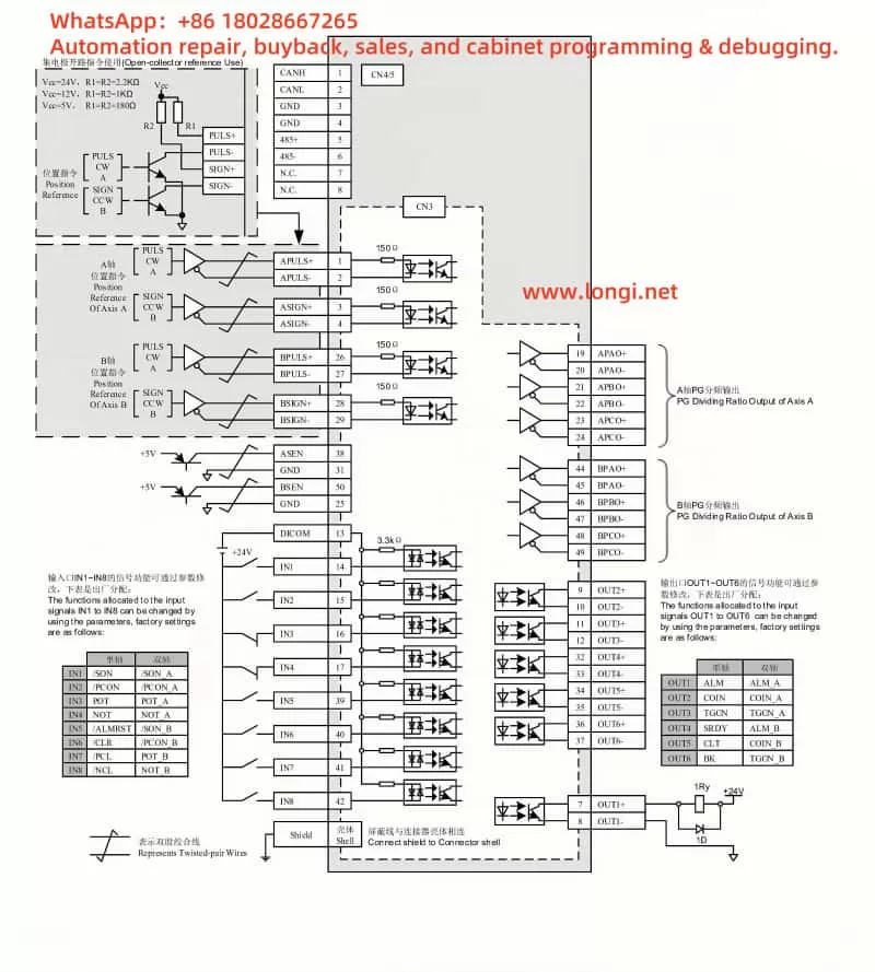
Step 1: Inspect Encoder Wiring

  • Action: Refer to Section 3.4, “Encoder Operation Guide Wiring” (Page 27), to verify the encoder cable connections.
  • Procedure:
    • Check that all connections to the encoder port (e.g., CN1 or CN2) are secure and free of corrosion or damage.
    • Ensure the cable shield is properly grounded, as recommended in Section 3.5 (Page 34), to minimize interference.
    • Use a multimeter to test the continuity of each wire in the encoder cable, identifying any breaks or shorts.
  • Outcome: If wiring issues are found, they must be corrected before proceeding.

Step 2: Test the Encoder Hardware

  • Action: Assess the encoder’s functionality, as suggested in Section 7.2, “Servo Drive Maintenance and Inspection” (Page 139).
  • Procedure:
    • Visually inspect the encoder for physical damage (e.g., cracked housing or burnt components).
    • If possible, swap the suspect encoder with a known working unit of the same model to see if the fault persists.
    • For advanced diagnostics, use an oscilloscope to monitor the encoder’s output signals, checking for irregularities in the waveform.
  • Outcome: A faulty encoder will require replacement.

Step 3: Evaluate Communication Environment

  • Action: Investigate potential interference, referencing Section 6.3, “MODBUS Communication Protocol” (Page 107).
  • Procedure:
    • Ensure the communication cable length complies with RS-485 standards (typically under 1200 meters).
    • Identify and mitigate EMI sources near the servo system, such as high-power machinery, by relocating them or adding shielding.
    • Verify that the cable routing avoids parallel runs with power lines, as advised in Section 3.8 (Page 36).
  • Outcome: Improved shielding or rerouting may resolve communication-related errors.

Step 4: Verify Power Supply Stability

  • Action: Check the power supply to the encoder and drive, per Section 3.2, “Typical Main Circuit Wiring Example” (Page 20).
  • Procedure:
    • Measure the input voltage to the servo drive (typically 220V ±10%) using a multimeter to ensure it’s within spec.
    • Monitor the encoder’s power supply voltage (often 5V or 24V) for stability, using an oscilloscope if available to detect fluctuations.
  • Outcome: Power instability may necessitate a regulated power source or additional filtering.

Step 5: Review Parameter Settings

  • Action: Validate encoder-related parameters, as outlined in Section 5.4.5, “Absolute Encoder Settings” (Page 69).
  • Procedure:
    • Access the servo drive’s parameter menu via the panel (Section 4.1, Page 38) and check settings like F[009] and F[010], which define encoder data formats.
    • Compare these settings against the encoder’s specifications and the manual’s recommendations.
    • If uncertain, reset to factory defaults (Section 4.2.6, Page 43) and reconfigure carefully.
  • Outcome: Corrected settings should eliminate configuration-induced errors.

Resolving the A.43 Fault

Once the cause is pinpointed, apply the appropriate fix:

  • Faulty Encoder: Replace it with a compatible unit, ensuring proper installation per Section 1.2, “Motor Model Naming” (Page 9).
  • Wiring Issues: Repair or replace damaged cables, secure connections, and enhance grounding as needed.
  • Communication Interference: Install noise filters (Section 4, Page 34), use ferrite cores, or adjust cable paths to reduce EMI.
  • Power Supply Problems: Add a voltage stabilizer or filter to ensure consistent power delivery.
  • Configuration Errors: Adjust parameters to match the encoder, save changes, and restart the drive.

After resolution, reset the fault via the panel (Section 4.1, Page 38) and test the system under normal operating conditions to confirm the fix.

ZSMC servo K standard wiring diagram

Preventive Measures

Preventing future A.43 faults requires proactive maintenance and optimization:

  • Routine Inspections: Regularly check the encoder, wiring, and connections for wear or damage (Section 7.2, Page 139).
  • Environmental Optimization: Maintain an operating environment within 0–40°C and <90% humidity, avoiding EMI sources.
  • Parameter Management: Document correct settings and verify them after any system changes.
  • Staff Training: Educate operators on proper handling and maintenance to avoid accidental damage.

Conclusion

The A.43 fault in the ZSMC K-Series servo drive, while disruptive, is manageable with a structured approach. By understanding its meaning—a bus-type encoder cumulative count error—and systematically addressing potential causes like hardware failure, wiring issues, or interference, users can restore functionality efficiently. The detailed manual provides a solid foundation for this process, supplemented by practical troubleshooting steps and preventive strategies. With diligent maintenance and adherence to best practices, the reliability of the ZSMC K-Series servo system can be upheld, ensuring seamless performance in demanding industrial applications.

Posted on Leave a comment

In-depth Analysis and Solutions for ERR14 Error in INDVS Y300 Series Variable Frequency Drive


Introduction

In modern industrial automation, variable frequency drives (VFDs) are pivotal for motor control, widely utilized across industries such as manufacturing, energy, and transportation. The INDVS Y300 series VFD stands out for its exceptional performance and reliability, making it a preferred choice for many businesses. However, users may occasionally encounter the ERR14 error, which indicates module overheating. This error can interrupt production and potentially damage equipment if not addressed promptly. This article offers an in-depth exploration of the ERR14 error, covering its technical basis, causes, solutions, and preventive strategies to help users maintain stable and efficient operations.

ERR14

Definition and Impact of ERR14 Error

According to the INDVS Y300 series VFD user manual, the ERR14 error is a safety feature triggered when the power module’s temperature exceeds a predetermined safe limit. The power module, a vital component, converts input power into the specific frequency and voltage needed to drive the motor. Overheating prompts the VFD to shut down automatically, protecting the system from further harm. While this protective mechanism is effective, repeated incidents can lower production efficiency and, in extreme cases, destabilize entire production lines. Addressing the ERR14 error is thus critical for operational continuity.

The consequences of overheating are far-reaching. Sustained high temperatures can accelerate the degradation of the power module, reducing its lifespan. Moreover, the downtime caused by such errors can lead to significant economic losses, especially in continuous-operation settings. Identifying and resolving the underlying issues quickly is therefore a key priority for users.

Potential Causes of ERR14 Error

Understanding the root causes of the ERR14 error is the first step toward effective resolution. Based on the user manual and practical insights, the following factors are commonly responsible:

1. Excessive Ambient Temperature

The VFD operates optimally within a temperature range of -10°C to 40°C, as specified in the manual. When ambient temperatures exceed this limit—such as during hot seasons or in confined spaces—heat dissipation becomes less efficient, resulting in module overheating.

2. Poor Ventilation

The VFD depends on internal fans and heat sinks to manage heat. Dust and debris buildup can block airflow, impairing the cooling system’s performance. The manual emphasizes regular cleaning to ensure effective ventilation.

3. Overloading

Prolonged operation under heavy loads causes the power module to generate excessive heat. Incorrect parameter settings, such as insufficient current limits, can worsen this problem. The manual links load levels to heat output, urging users to configure settings carefully.

4. Improper Installation

The VFD’s installation site and surrounding space affect heat dissipation. The manual advises maintaining adequate clearance around the unit and avoiding proximity to heat sources or stacked equipment. Non-compliance with these guidelines can lead to heat buildup.

Y300

Diagnosis and Solutions for ERR14 Error

When the ERR14 error occurs, immediate action is necessary. Below is a step-by-step guide to diagnose and resolve the issue:

1. Safe Power-Down and Cooling

Upon receiving the overheating alert, disconnect the power supply and let the VFD cool down to a safe temperature. The manual suggests using a soft brush or compressed air to clean the cooling system, cautioning against liquids to avoid damaging components.

2. Inspect the Cooling System

Open the VFD casing to check the fans for proper operation and the heat sinks for dust accumulation. Replace faulty fans and ensure clear airflow paths.

3. Parameter Adjustment

Access the control panel to confirm that current limits and thermal protection settings are appropriate. The manual provides guidance on adjusting these parameters, recommending that users save the original settings beforehand.

4. Motor and Wiring Inspection

Use an insulation tester to detect short circuits or insulation issues in the motor and wiring. Such faults can cause abnormal currents, indirectly contributing to overheating.

Preventive Measures and Long-Term Solutions

Fixing the ERR14 error is only part of the solution; preventing its recurrence is equally vital. Here are some proactive steps:

1. Regular Maintenance

Set up a routine maintenance plan, including monthly cleaning of the cooling system and quarterly reviews of fans and settings. The manual’s suggested intervals can guide this schedule.

2. Environmental Optimization

Install the VFD in a well-ventilated, temperature-regulated area. In hot environments, consider adding external cooling solutions like fans or air conditioning.

3. Operator Training

Provide thorough training on the manual’s operational guidelines, ensuring staff can adjust parameters and perform inspections competently, thus improving equipment oversight.

4. Smart Monitoring

Utilize the Modbus communication protocol outlined in the manual to implement a temperature monitoring system. This allows real-time observation of module conditions and early warnings of potential issues.

Technical Principles and Application Scenario Analysis

To fully grasp the ERR14 error, it helps to examine its technical origins. The power modules in VFDs typically employ Insulated Gate Bipolar Transistors (IGBTs), which produce heat during operation. This heat is proportional to the square of the current and the switching frequency. High loads or overly permissive parameter settings increase heat buildup. If the cooling system cannot dissipate this heat effectively, the temperature exceeds the safety threshold, activating the ERR14 error.

In real-world scenarios—like pump control in petrochemical plants or spindle drives in textile production—VFDs often face sustained high loads. These applications demand robust cooling designs and precise parameter tuning. During selection and setup, users must evaluate operational needs carefully to prevent problems arising from poor planning.

Conclusion

The ERR14 error in the INDVS Y300 series VFD, though a frequent challenge, can be managed systematically. By understanding its causes, applying targeted fixes, and adopting preventive measures, users can minimize overheating risks, ensuring the equipment’s long-term reliability and performance. This article has offered a detailed roadmap—from technical details to actionable steps—to empower users in mastering industrial automation challenges with confidence.

Posted on Leave a comment

Analysis and Solutions for ERR10 Fault in CANWORLD CDE300 Series Inverter

Introduction

The CANWORLD CDE300 series inverter is a high-performance variable frequency drive (VFD) designed for three-phase motor control, widely used in industrial automation. Its primary functions include adjusting motor speed, improving energy efficiency, and ensuring smooth equipment operation. However, in practical applications, inverters may encounter faults due to various reasons. Among these, the ERR10 fault—indicating module overheating—is a common alarm that requires prompt attention to prevent equipment damage or downtime.

This article is based on the “CDE300 CANWORLD Three-Phase User Manual V1.10.pdf” and the provided fault screenshot. It provides an in-depth discussion of the ERR10 fault, including its meaning, potential causes, troubleshooting steps, and preventive measures. Through a clear structure and logical analysis, this article aims to offer practical guidance to help users quickly resolve module overheating issues and ensure long-term stable operation of the equipment.

ERR10

Meaning of ERR10 Fault

The ERR10 fault in the CANWORLD CDE300 series inverter specifically indicates “module overheating.” The power module of the inverter, typically composed of core components such as Insulated Gate Bipolar Transistors (IGBTs), is responsible for converting the input power into the appropriate output voltage and frequency for motor operation. During operation, these components generate significant heat due to energy losses. To protect the equipment, the inverter is equipped with temperature sensors that monitor the power module’s temperature in real time. When the temperature exceeds a safe threshold, the system triggers the ERR10 fault alarm and may automatically shut down to prevent further thermal damage.

The consequences of module overheating should not be underestimated. Prolonged high temperatures can lead to IGBT aging, performance degradation, and even permanent damage to the power module. Therefore, accurately understanding the ERR10 fault and taking effective measures are crucial.

Possible Causes of ERR10 Fault

Module overheating is usually caused by a combination of factors. Based on the design features of the CDE300 series inverter, the user manual, and common issues in industrial applications, the following are the main potential causes of the ERR10 fault:

  1. High Ambient Temperature
    According to the “Installation Site” section in Chapter 3 (PAGE22) of the user manual, the operating ambient temperature for the CDE300 series inverter should typically be between -10°C and 40°C. If the installation environment exceeds this range, the inverter’s cooling system may be unable to effectively reduce the module temperature, triggering the ERR10 fault.
  2. Poor Ventilation
    The inverter requires adequate airflow for heat dissipation. The manual mentions the need for sufficient space around the inverter during installation (PAGE13, Section 2.5.1 “Product Installation Dimensions”). If the installation location is too confined or near other heat sources, heat accumulation may occur, affecting cooling efficiency.
  3. Cooling System Failure or Blockage
    The CDE300 series inverter relies on built-in fans and heat sinks for thermal management. If the fan stops working, operates at reduced speed, or if the heat sink is clogged with dust or grease, cooling efficiency will significantly decrease. This is particularly common in industrial environments where the air may contain a high concentration of particulates.
  4. Overloaded Condition
    When the load driven by the inverter exceeds its rated capacity, the power module will bear higher current and thermal stress. The manual’s Section 2.3 “CDE300 Series Inverter Models” (PAGE9) lists the rated power for each model, such as CDE300-4T7R5G/011P. If the actual load exceeds the specifications, it may lead to module overheating.
  5. Wiring Issues
    Incorrect electrical installation (such as loose or poor connections) can increase resistance, generating additional heat. Section 3.2 “Electrical Installation” (PAGE25) and the “Main Contents of the Distribution Room” on PAGE30 emphasize the importance of proper wiring and grounding. Wiring errors may indirectly cause the ERR10 fault.
  6. High Switching Frequency
    A higher switching frequency in IGBTs results in increased heat generation. If the switching frequency is set too high in the inverter’s parameters, it may exacerbate the thermal load on the module, leading to overheating.
  7. Hardware Failure
    If all external factors are normal, the issue may lie with the power module or temperature sensor itself, such as a damaged IGBT or a malfunctioning sensor reporting false high temperatures.
CDE300

Troubleshooting and Solutions for ERR10 Fault

To resolve the ERR10 fault and restore the inverter to normal operation, users can follow these step-by-step troubleshooting procedures:

1. Power Off and Cool Down the Equipment

Upon detecting the ERR10 fault, immediately turn off the inverter’s power and allow the equipment to cool naturally. The “Safety Markings” section in Chapter 1.1 (PAGE4) recommends waiting at least 10 minutes after powering off to ensure internal components have cooled and to avoid safety risks.

2. Check Ambient Temperature

Use a thermometer to measure the temperature around the inverter, ensuring it is within the -10°C to 40°C range. If the temperature is too high, improve environmental conditions by adding ventilation equipment (such as fans or air conditioning) or relocating the inverter.

3. Assess Ventilation and Installation

Refer to Section 2.5 “Product Type Diagram and Installation Hole Dimensions” (PAGE11-13) in the manual to check if there is sufficient space around the inverter (e.g., clearances in front, back, left, and right). Remove any objects that may obstruct airflow and ensure the inverter is not near other heat sources.

4. Clean the Cooling System

Inspect whether the fan is operating normally and clean any dust or debris from the fan blades and heat sink. Use compressed air or a soft brush for cleaning to ensure unobstructed airflow. If the fan is faulty, test its electrical connections and consider replacement.

5. Verify Load Matching

Check if the load parameters match the inverter’s rated capacity (see PAGE9). If the load is too high, reduce the operating load or upgrade to a higher power model. Additionally, inspect the motor for abnormalities (such as short circuits or mechanical jams) that could cause excessive current.

6. Inspect Electrical Connections

Follow the requirements in Section 3.2 “Electrical Installation” (PAGE25) to check the main circuit connections (R, S, T, U, V, W) and grounding (P, P+, P-) for secure and intact connections without looseness or aging. Ensure the input voltage is within the specified range to avoid overcurrent.

7. Adjust Switching Frequency

Using the keypad operation (Chapter 4, PAGE37), access the parameter settings interface to check and reduce the switching frequency (if the application allows). This can decrease the heat generated by the IGBTs, but be cautious not to affect motor performance.

8. Monitor Operation and Test

After completing the above adjustments, restart the inverter and observe its operating status. If the equipment provides temperature display functionality, monitor the module temperature in real time. If the ERR10 fault persists, it may indicate a hardware issue, and it is recommended to contact CANWORLD technical support for further inspection.

Preventive Measures for ERR10 Fault

To prevent the recurrence of the ERR10 fault, users can implement the following preventive measures:

  1. Regular Maintenance
    Conduct a comprehensive inspection of the inverter every 3-6 months, cleaning the fan and heat sink to ensure the cooling system functions properly. In industrial environments, maintenance intervals may need to be shortened.
  2. Optimize Installation Environment
    Choose a well-ventilated installation location away from heat sources, avoiding direct sunlight or high-temperature areas, in accordance with Section 3.1 of the manual.
  3. Proper Load Management
    Monitor load conditions in real time to avoid prolonged overload operation. Utilize the inverter’s built-in diagnostic functions or external devices to track current and temperature.
  4. Parameter Optimization
    Adjust operating parameters based on actual application needs, such as switching frequency and acceleration/deceleration times, to minimize unnecessary heat generation.
  5. Personnel Training
    Train operators to familiarize them with the safety and installation guidelines in the manual and to equip them with basic troubleshooting skills.
  6. Enhanced Cooling Measures
    In high-temperature environments, install additional external fans or air conditioning to further improve heat dissipation.

Conclusion

The ERR10 fault (module overheating) in the CANWORLD CDE300 series inverter is a critical protective alarm that may be triggered by high ambient temperatures, poor ventilation, cooling system failures, overloaded conditions, wiring issues, or hardware malfunctions. Through systematic troubleshooting—from checking the environment to adjusting parameters and performing maintenance—users can typically identify and resolve the issue quickly. Additionally, by implementing regular maintenance and optimizing the operating environment, the likelihood of ERR10 faults can be significantly reduced.

The CDE300 series inverter is renowned for its reliability, but its performance depends on proper installation and maintenance. By following the guidelines in the user manual and the solutions and preventive suggestions provided in this article, users can not only address current module overheating issues but also enhance the overall lifespan and efficiency of the equipment, ensuring stability and safety in industrial applications. For complex issues, it is advisable to contact CANWORLD’s official technical support for professional assistance.

Posted on

Panasonic VF200 Series Inverter “CPU” Fault and ALARM Light Resolution Guide

1. Introduction

The Panasonic VF200 series inverter is a widely used device in industrial automation, known for its efficiency, reliability, and versatility. This series supports single-phase 200V (0.2kW to 2.2kW) and three-phase 400V (0.75kW to 15kW) power supplies, making it suitable for various motor control applications. However, users may encounter issues during operation, one of the most common and troubling being the “CPU” fault code displayed on the inverter’s screen accompanied by the ALARM light. This fault indicates an abnormality in the inverter’s core control system, potentially causing the device to stop functioning and disrupting production efficiency. This article will provide a detailed analysis of the “CPU” fault, its possible causes, and a systematic approach to troubleshooting and resolving the issue to help users quickly restore normal operation.

CPU ALARM

2. Meaning of the “CPU” Fault

In the Panasonic VF200 series inverter, when the display shows the “CPU” fault code and the ALARM light is on, it typically indicates a problem with the inverter’s Central Processing Unit (CPU). The CPU is the “brain” of the inverter, responsible for executing control algorithms, processing input and output signals, and coordinating the overall operation of the device. When the CPU detects an abnormality in itself or related systems, the inverter enters protection mode, stops operation, and alerts the user by displaying the “CPU” code and lighting the ALARM lamp.

According to the VF200 series user manual and technical documentation, the “CPU” fault may be associated with other anomalies such as instantaneous overcurrent (OC1-3) or temperature abnormalities (OH). This suggests that the “CPU” error may not solely be a hardware issue with the CPU but could also be triggered indirectly by external conditions or system operational states. Therefore, understanding the potential causes of this fault is crucial.

3. Possible Causes of the “CPU” Fault

The occurrence of the “CPU” fault can be triggered by various factors. Below are detailed analyses of several common causes:

1. Power Supply Issues

  • Voltage Instability: The VF200 series inverter has strict requirements for input power. If the power supply voltage exceeds the rated range (single-phase 200V or three-phase 400V) or fluctuates, it may lead to insufficient power or overvoltage damage to the CPU.
  • Power Interference: Surges or electromagnetic interference (EMI) in the power supply can disrupt the normal operation of the CPU, especially in industrial environments with poor power quality.

2. Overheating Issues

  • Temperature Abnormality (OH): If the internal temperature of the inverter is too high, it may be due to poor ventilation, high ambient temperature, or a malfunctioning cooling fan (FAn). High temperatures can affect the stability of the CPU and even trigger faults.
  • Overloading: Operating under high load conditions for extended periods can lead to inadequate heat dissipation, further exacerbating temperature increases.

3. Overcurrent Issues

  • Instantaneous Overcurrent (OC1-3): Motor failures, sudden load changes, or wiring errors can cause the current to exceed the inverter’s rated value. This situation may place excessive stress on the CPU, triggering the protection mechanism and displaying the “CPU” error.
  • Improper Parameter Settings: If the current limit parameters are set incorrectly, it may fail to effectively prevent overcurrent conditions.

4. Firmware or Software Issues

  • Firmware Corruption: Firmware is the software foundation for CPU operation. If the firmware is corrupted during an update or due to electrical interference, the CPU may not function properly.
  • Parameter Errors: Parameters set by the user that do not match the actual application may cause the CPU to execute abnormal instructions.

5. Hardware Failures

  • CPU or Control Board Damage: Long-term use, manufacturing defects, or physical damage can lead to hardware failures in the CPU or its control board, such as circuit board burnout or component aging.
  • Connection Issues: Loose or poor internal connections may disrupt data communication between the CPU and other modules.

6. External Interference

  • Electromagnetic Interference: High-power equipment commonly found in industrial environments can generate strong electromagnetic interference, affecting the CPU’s signal processing capabilities.
  • Poor Grounding: High grounding resistance can lead to the accumulation of electrical noise, interfering with CPU operation.
VF200

4. Steps to Troubleshoot and Resolve the “CPU” Fault

To effectively resolve the “CPU” fault, users should follow these systematic steps for troubleshooting and resolution:

1. Initial Checks and Safety Preparations

  • Power Off: According to the warning labels on the inverter, disconnect the power and wait at least 5 minutes to ensure the internal capacitors are discharged, avoiding the risk of electric shock.
  • Record Status: Note the operating conditions when the “CPU” fault occurred (such as load, ambient temperature, etc.) to provide clues for subsequent diagnosis.

2. Check Power Supply Conditions

  • Measure Voltage: Use a multimeter to measure the input power voltage, ensuring it is within the rated range for single-phase 200V (0.2kW to 2.2kW) or three-phase 400V (0.75kW to 15kW) and free from significant fluctuations.
  • Check Grounding: Confirm that the grounding resistance is less than 10 ohms to eliminate interference caused by poor grounding.

3. Check for Overheating Issues

  • Ambient Temperature: Ensure the operating environment temperature is between 0°C and 40°C, and check if the ventilation openings are blocked.
  • Cooling Fan: Verify if the fan is operating normally; replace it if faulty.
  • Clean the Device: Use compressed air to remove dust from inside the inverter to ensure proper heat dissipation.

4. Check for Overcurrent Issues

  • Load Check: Ensure the motor load does not exceed the inverter’s rated capacity and check for motor short circuits or mechanical jams.
  • Wiring Check: Inspect the wiring between the inverter and the motor to ensure it is correct and secure.
  • Parameter Adjustment: Use the “MODE,” “SET,” “UP,” and “DOWN” keys to access parameter settings and check the current limit parameters, ensuring they are within 1% to 200% of the rated output current.

5. Reset and Firmware Check

  • Power Reset: After powering off and waiting 5 minutes, power on again to see if the “CPU” error disappears.
  • Restore Factory Settings: If the issue persists, follow the user manual to restore factory settings and then reconfigure necessary parameters.
  • Firmware Update: Contact technical support to obtain the latest firmware and follow the instructions to update it.

6. Hardware Inspection

  • Visual Inspection: Open the inverter casing and check the control board for signs of burning, odors, or damaged components.
  • Connection Repair: If loose connections are found, secure them with insulating tape and re-tighten.
  • Component Replacement: If hardware damage is severe, contact Panasonic after-sales service to replace the original control board.

7. Reduce External Interference

  • Isolate Interference Sources: Separate the inverter from high-power equipment or install shielding covers.
  • Use Shielded Cables: Ensure that control signal lines and power lines use shielded cables to reduce electromagnetic interference.

8. Testing and Verification

  • Operation Test: After completing the above steps, restart the inverter and observe if the “CPU” error is resolved.
  • Diagnostic Function: Use the inverter’s error log function to check for other related fault codes (such as OC1-3, OH, etc.).

9. Seek Professional Support

  • If the issue remains unresolved, contact Panasonic technical support, providing detailed fault information, model (VF200), and troubleshooting records for remote diagnosis or on-site repair.

5. Preventive Measures for “CPU” Faults

To prevent the recurrence of “CPU” faults, users can take the following preventive measures:

  1. Regular Maintenance
  • Clean dust every 6 months, check wiring and fan status to ensure proper heat dissipation and electrical connections.
  1. Power Optimization
  • Install voltage stabilizers or UPS to ensure stable power supply and avoid voltage spikes.
  1. Environmental Management
  • Keep the operating environment clean, dry, and avoid high temperatures and humidity, ensuring good ventilation.
  1. Firmware Management
  • Regularly check firmware versions, back up parameters before updating to ensure software stability.
  1. Standardized Operation
  • Train operators to set parameters correctly according to the user manual to avoid malfunctions caused by incorrect operations.

6. Conclusion

The “CPU” fault displayed on the Panasonic VF200 series inverter, accompanied by the ALARM light, is a serious issue that requires prompt attention. It can be caused by power instability, overheating, overcurrent, firmware issues, hardware failures, or external interference. By following the systematic troubleshooting steps provided in this article, users can start with checking power and environmental conditions, then delve into hardware and firmware aspects to identify the root cause and apply targeted solutions. Additionally, regular maintenance and optimizing the operating environment are key to preventing faults. If self-troubleshooting fails, contacting Panasonic’s official support is advisable. Through these methods, users can not only resolve the current “CPU” fault but also enhance the long-term stability and lifespan of the equipment, ensuring reliable support for industrial production.


Posted on

User Guide for the JLS Inverter E Series Manual

Introduction

The JLS Inverter E Series is a high-performance motor control device widely used in industrial automation. Its user manual provides comprehensive guidance on installation, configuration, and maintenance, enabling users to operate the inverter efficiently. This article, based on the manual, offers a detailed guide on the operation panel functions, terminal-based forward/reverse control, external potentiometer frequency adjustment, and common fault codes with their solutions. The goal is to provide users with a practical and thorough reference for utilizing the JLS Inverter E Series effectively.


Functional Diagram of the Operation Panel for Julishen (or Julishen Brand) E-series Frequency Inverter

1. Operation Panel Functions

The operation panel is the primary interface for interacting with the JLS Inverter E Series, allowing users to configure parameters, monitor operations, and diagnose faults. Below is an overview of its key functions and usage instructions.

1.1 Display and Function Buttons

  • Display Screen: The LCD screen displays real-time information such as parameter values, operating frequency, output current, and fault codes. It supports multiple language options for user convenience.
  • Function Buttons:
    • PRG/ENTER Key: Enters parameter programming mode or confirms parameter changes.
    • Up/Down Keys (▲/▼): Navigate through parameter lists or adjust parameter values.
    • Left/Right Keys (◄/►): Switch between parameter groups or move the cursor during parameter editing.
    • RUN Key: Starts the inverter, initiating motor operation.
    • STOP/RESET Key: Stops the inverter or resets it during a fault condition.
  • DIP Switch: Located inside the operation panel, used to set parameter access restrictions.

1.2 Restoring Factory Settings

To reset the inverter to its default configuration, follow these steps to restore factory settings:

  1. Press the PRG/ENTER Key to enter programming mode.
  2. Use the ▲/▼ Keys to select the parameter group “F0” (Basic Function Group).
  3. Use the ◄/► Keys to locate parameter “F0.00” (Restore Factory Settings).
  4. Set “F0.00” to “1” (indicating a factory reset).
  5. Press the PRG/ENTER Key to confirm.
  6. The inverter will restart automatically, restoring all parameters to their factory defaults.

1.3 Setting and Clearing Passwords

To prevent unauthorized parameter modifications, the inverter supports password protection. Below are the steps to set and clear a password:

  • Setting a Password:
    1. Enter programming mode by pressing the PRG/ENTER Key.
    2. Select the “F0” parameter group.
    3. Navigate to parameter “F0.01” (Password Setting).
    4. Enter a 4-digit password (e.g., “1234”).
    5. Press the PRG/ENTER Key to save the password.
  • Clearing a Password:
    1. Enter programming mode.
    2. Input the current password to unlock parameter access.
    3. Navigate to parameter “F0.01”.
    4. Set “F0.01” to “0” (to disable the password).
    5. Press the PRG/ENTER Key to confirm.

1.4 Parameter Access Restrictions

Parameter access can be restricted using the DIP switch inside the operation panel. Follow these steps:

  1. Open the operation panel to access the internal DIP switch.
  2. Set the switch position based on the desired access level:
    • Position 1 (ON): Allows access to all parameters.
    • Position 2 (OFF): Restricts access to advanced parameters, allowing only basic parameters to be modified.
  3. Close the panel and restart the inverter to apply the settings.

Standard Wiring Diagram for Julishen E-series Frequency Inverter

2. Terminal-Based Forward/Reverse Control and External Potentiometer Frequency Adjustment

The JLS Inverter E Series supports motor forward/reverse control via terminals and frequency adjustment using an external potentiometer. Below are the detailed steps for implementation.

2.1 Wiring Configuration

  • Forward/Reverse Control:
    • Connect an external switch or PLC output to the inverter’s “FWD” (forward) and “REV” (reverse) terminals.
    • Connect the control signal’s common terminal to the “COM” terminal.
  • External Potentiometer Frequency Adjustment:
    • Connect the potentiometer’s middle tap to the “AI1” terminal (Analog Input 1).
    • Connect the potentiometer’s two ends to the “+10V” (power supply) and “GND” (ground) terminals.

2.2 Parameter Settings

  • Forward/Reverse Control:
    1. Enter programming mode.
    2. Select parameter group “F1” (Operation Control Group).
    3. Set “F1.00” (Operation Command Source) to “1” (Terminal Control).
    4. Set “F1.01” (Forward Control) to “0” (FWD terminal controls forward rotation).
    5. Set “F1.02” (Reverse Control) to “1” (REV terminal controls reverse rotation).
  • External Potentiometer Frequency Adjustment:
    1. Enter programming mode.
    2. Select parameter group “F2” (Frequency Setting Group).
    3. Set “F2.00” (Frequency Reference Source) to “2” (AI1 Analog Input).
    4. Based on the potentiometer’s characteristics, configure parameters “F2.01” (AI1 Minimum Input) to “F2.04” (AI1 Maximum Input) to calibrate the frequency range.
      • Example: Set “F2.01” to 0V corresponding to 0Hz and “F2.04” to 10V corresponding to 50Hz.

3. Fault Codes and Troubleshooting

The JLS Inverter E Series manual lists common fault codes and their troubleshooting methods. Below are typical faults and their solutions:

  • E001: Overcurrent Fault
    • Cause: Excessive motor load, overly short acceleration time, or output short circuit.
    • Solution:
      • Check and reduce motor load.
      • Extend acceleration time (adjust parameter “F3.01”).
      • Inspect output wiring to ensure no short circuits.
  • E002: Overvoltage Fault
    • Cause: High supply voltage, overly short deceleration time, or faulty braking resistor.
    • Solution:
      • Verify power supply voltage stability.
      • Extend deceleration time (adjust parameter “F3.02”).
      • Check the braking resistor for damage or poor connection.
  • E003: Undervoltage Fault
    • Cause: Low supply voltage or poor wiring connections.
    • Solution:
      • Ensure the power supply voltage is within the specified range.
      • Check wiring connections for secure contacts.
  • E004: Overheat Fault
    • Cause: Poor heat dissipation, high ambient temperature, or faulty fan.
    • Solution:
      • Improve ventilation to enhance heat dissipation.
      • Reduce ambient temperature.
      • Inspect fan operation and replace if necessary.
  • E005: Motor Overload
    • Cause: Excessive load or incorrect motor parameter settings.
    • Solution:
      • Reduce motor load.
      • Verify that motor parameters match the actual motor specifications.

Conclusion

The JLS Inverter E Series is a versatile and robust solution for industrial motor control, offering flexible configuration options and reliable performance. Mastering the user manual’s instructions is critical for ensuring stable operation and extending the equipment’s lifespan. This article has provided a comprehensive guide to the operation panel functions, terminal control setup, and fault troubleshooting, serving as a practical reference for users. In practice, adhere strictly to the manual’s guidelines and perform regular maintenance to ensure the inverter’s safety and reliability.

Posted on

User Guide for the Yuxin L Series Inverter Manual

Introduction

A Variable Frequency Drive (VFD) is an electronic device that controls the speed of an AC motor by adjusting the power supply’s frequency and voltage. It is widely used in industrial automation, energy management, and mechanical equipment control. The Yuxin L Series Inverter is a high-performance product known for its reliability and user-friendliness. This guide provides detailed instructions on using the inverter, covering the operation panel functions, terminal-based forward/reverse control, external potentiometer frequency adjustment, fault codes, and troubleshooting methods. The aim is to help users quickly master the device and utilize it effectively.


Structural Schematic Diagram of Yuxin L-series Frequency Inverter

Part 1: Operation Panel Functions

The operation panel is the primary interface for interacting with the Yuxin L Series Inverter, enabling parameter configuration, status monitoring, and fault resetting. This section details the panel’s functionalities and specific settings.

1.1 Panel Layout and Button Functions

The Yuxin L Series Inverter’s operation panel typically features an LCD display and several function buttons. The display shows operational status, parameter numbers, parameter values, and fault codes. Common buttons and their functions include:

  • MENU/ESC: Enter or exit the parameter setting menu.
  • UP/DOWN: Navigate the menu or adjust parameter values.
  • ENTER: Confirm selections or save parameter settings.
  • RUN: Start the inverter’s operation.
  • STOP/RESET: Stop the inverter or reset a fault condition.

Users are advised to familiarize themselves with the panel layout and refer to the manual’s panel diagram to ensure accurate operation.

1.2 Restoring Factory Settings

In cases such as incorrect parameter configurations or the need for reinitialization, restoring the inverter to factory settings may be necessary. Follow these steps:

  1. Press the MENU/ESC button to access the main menu.
  2. Use the UP/DOWN buttons to locate the “Parameter Management” or similar option (refer to the manual for the exact name).
  3. Press ENTER to enter the submenu.
  4. Select the “Restore Factory Settings” option.
  5. Press ENTER to confirm. The inverter will reset all parameters to their default values.
  6. Wait for the display to indicate completion, typically taking a few seconds.

Note: Restoring factory settings will erase all custom parameters. Back up important data beforehand.

1.3 Setting and Clearing a Password

To prevent unauthorized parameter changes, the Yuxin L Series Inverter supports password protection. Below are the steps to set and clear a password:

Setting a Password

  1. Navigate to the “Parameter Management” menu.
  2. Locate the “Password Setting” option.
  3. Press ENTER and input a 4-digit password (e.g., “1234”).
  4. Press ENTER to save. The password will take effect.
  5. The next time you access parameter settings, the password will be required.

Clearing a Password

  1. Enter the “Password Setting” menu.
  2. Input the current password for verification.
  3. Set the password value to “0000” or leave it blank (check the manual for specifics).
  4. Press ENTER to save, and the password will be cleared.

Tip: If you forget the password, restoring factory settings may be required, but this will also reset other parameters.

1.4 Parameter Access Restrictions

Parameter access restrictions allow locking specific parameters to prevent accidental or unauthorized modifications. The process is as follows:

  1. Access the “Parameter Management” menu.
  2. Select the “Parameter Lock” or similar option.
  3. Specify the parameter group to lock (e.g., advanced parameters or specific function parameters).
  4. Set the lock status (typically “1” for locked, “0” for unlocked).
  5. Press ENTER to save.
  6. If a password is set, it will be required to modify locked parameters.

This feature allows flexible control over parameter accessibility, ensuring safe operation.


Standard Wiring Diagram for Yuxin L-series Frequency Inverter

Part 2: Terminal-Based Forward/Reverse Control and External Potentiometer Frequency Adjustment

The Yuxin L Series Inverter supports terminal-based control and frequency adjustment, enabling precise motor control. This section explains how to implement forward/reverse control and frequency adjustment using an external potentiometer, including wiring and parameter settings.

2.1 Terminal-Based Forward/Reverse Control

Terminal-based forward/reverse control is a common method for applications requiring external switches or PLC control.

Wiring Method

  • Connect the forward switch to the digital input terminal DI1 and the common terminal COM.
  • Connect the reverse switch to the digital input terminal DI2 and the common terminal COM.
  • Ensure secure connections and refer to the manual’s terminal layout diagram to confirm terminal positions.

Parameter Settings

  1. Set parameter P0.01 (Control Mode) to “1” to select terminal control mode.
  2. Set parameter P4.00 (DI1 Function) to “1” to designate DI1 as the forward run command.
  3. Set parameter P4.01 (DI2 Function) to “2” to designate DI2 as the reverse run command.
  4. Save the settings. Closing the DI1 switch initiates forward rotation, and closing the DI2 switch initiates reverse rotation.

Note: Parameter numbers may vary by model. Refer to the manual’s parameter table for accuracy.

2.2 External Potentiometer Frequency Adjustment

Using an external potentiometer for frequency adjustment allows smooth speed control, ideal for applications requiring manual adjustments.

Wiring Method

  • Connect the potentiometer’s center tap to the analog input terminal AI1.
  • Connect one end of the potentiometer to the +10V terminal (provides reference voltage).
  • Connect the other end to the GND terminal (ground).
  • Use an appropriate potentiometer (typically 10kΩ) and ensure correct wiring.

Parameter Settings

  1. Set parameter P0.03 (Frequency Reference Source) to “2” to select analog input AI1 for frequency setting.
  2. Verify parameter P4.10 (AI1 Input Range) matches the potentiometer’s voltage range (typically 0-10V).
  3. Save the settings. Rotating the potentiometer adjusts the output frequency.

Tip: If the frequency adjustment range is not as expected, adjust related parameters (e.g., maximum frequency P0.11).


Part 3: Fault Codes and Troubleshooting

During operation, the inverter may encounter faults, displayed as fault codes on the screen. This section lists common fault codes and their solutions, but refer to the manual’s fault list for specific codes.

3.1 Common Fault Codes and Solutions

  • E001: Overcurrent
    • Possible Causes: Excessive motor load, short acceleration time, or incorrect motor wiring.
    • Solutions:
      1. Check motor wiring for short circuits or poor connections.
      2. Reduce the load or increase the acceleration time (parameter P0.12).
      3. Restart the inverter to check if the issue resolves.
  • E002: Overvoltage
    • Possible Causes: High input voltage, short deceleration time, or braking unit failure.
    • Solutions:
      1. Verify the power supply voltage is within the specified range.
      2. Extend the deceleration time (parameter P0.13).
      3. If frequent, check the braking resistor for proper function.
  • E003: Undervoltage
    • Possible Causes: Low power supply voltage or unstable power.
    • Solutions:
      1. Ensure the input power voltage is stable.
      2. For multiple devices, confirm adequate power supply capacity.
  • E004: Motor Overload
    • Possible Causes: Excessive load or incorrect motor parameter settings.
    • Solutions:
      1. Reduce the load or select a motor with higher power capacity.
      2. Verify motor parameters (P1 group) match the actual motor.
  • E005: Inverter Overheating
    • Possible Causes: High ambient temperature or blocked/faulty cooling fan.
    • Solutions:
      1. Improve ventilation and reduce ambient temperature.
      2. Clean the fan and heatsink to ensure proper cooling.

3.2 General Troubleshooting Steps

  1. Record the fault code and consult the manual for its specific meaning.
  2. Inspect wiring, power supply, and load conditions to rule out external issues.
  3. Press STOP/RESET to attempt a reset. If unsuccessful, power cycle the inverter.
  4. If the issue persists, contact technical support with detailed fault information.

Conclusion

The Yuxin L Series Inverter offers robust functionality and flexible configuration, making it an excellent choice for motor control applications. This guide has detailed the operation panel’s usage, terminal-based control and frequency adjustment methods, and fault troubleshooting procedures. Due to model variations and application complexity, users should always refer to the official Yuxin L Series Inverter Manual for precise details. By mastering these foundational skills, you can fully leverage the inverter’s capabilities, enhance equipment efficiency, and address potential issues promptly.

Posted on

AnyHz FST-650 Inverter Err13 Output Phase Loss Fault Analysis and Troubleshooting

1. Introduction

In industrial applications, inverters play a crucial role in motor speed control. Their performance directly affects system efficiency and reliability. The AnyHz (Anyi) FST-650 series inverter is widely used in fans, pumps, and compressors. Among its common faults, “Err13” is frequently encountered, indicating output phase loss. This article provides a comprehensive analysis of Err13, including its causes, diagnosis steps, parameter tuning, and long-term solutions.


ERR13

2. Meaning of Err13

According to the official user manual and display panel codes:

Fault Code: Err13
Fault Description: Power output phase loss

“Output phase loss” means that the inverter detects one of the output phases (U, V, or W) is missing or the current is significantly abnormal, triggering a protective shutdown.


3. Common Causes of Err13

1. Loose or poor motor terminal connections

Caused by vibrations, poor tightening, corrosion, or wear, leading to poor contact on U/V/W terminals.

2. Damaged output cables

Aging insulation, rodents, mechanical stress, or improper bending could break one phase of the cable.

3. Motor winding failure

One phase of the stator coil is open due to burnout or manufacturing defects.

4. Inverter output module failure

The internal IGBT or current sensing circuit of the FST-650 is damaged, causing abnormal or missing output.

5. Output fuse blown (if used externally)

Some systems use fuses on each output phase. A blown fuse on one phase can cause Err13.


4. On-Site Troubleshooting Steps

Step 1: Confirm if it’s a false alarm

  • Use a clamp meter to measure U, V, W phase currents.
  • Use a multimeter to check motor winding resistance symmetry.

Step 2: Inspect output cables

  • Check all wiring terminals for secure connection and signs of overheating.
  • Inspect cable routing for physical damage or moisture ingress.

Step 3: Test motor condition

  • Use a megohmmeter to check insulation.
  • If possible, replace with another working motor to isolate the issue.

Step 4: Inspect inverter internals

  • Check IGBT module, driver board, and current sensors.
  • Observe for damaged components or abnormal heating.

5. Relevant Parameter Settings

The FST-650 inverter detects output phase loss via current monitoring and software logic. The following parameters affect phase loss detection:

Parameter No.NameRecommended SettingDescription
F9.10Phase loss detection enable1 (Enable)Turns on the function
F9.11Detection delay time0.2–2.0sAvoids false alarms
F2.10Torque/current limit≥110%Avoids misjudgment as overcurrent
F0.17 / F0.18Acceleration / deceleration time10–30sPrevents current overshoot

6. Repair Actions

1. Re-tighten U/V/W terminal screws

Ensure all output terminals are properly secured.

2. Replace or test output cable

Swap suspected cables with known good ones to isolate faults.

3. Test or replace the motor

If the motor is suspected, test with a known good motor and observe for recurrence.

4. Repair or replace inverter output module

If all external components are normal, the inverter’s power module or current sensor may need replacement.


7. Prevention and Maintenance Tips

  1. Regular tightening of output terminals, especially in vibrating machinery.
  2. Quarterly insulation testing of cables and motor windings.
  3. Install output phase monitoring relay to detect early signs of failure.
  4. Ensure proper cooling and dust protection for the inverter panel.
  5. For critical systems, consider motor + encoder + phase monitor redundancy setup.

AnyHz FST-650L

8. Conclusion

The Err13 “Output Phase Loss” fault on AnyHz FST-650 inverters is a critical protection mechanism that prevents motor damage. While often caused by external wiring or motor faults, internal inverter failures can also trigger this alarm. Systematic diagnosis and parameter adjustments, along with preventive maintenance, will greatly improve system uptime. If issues persist, consult with qualified service professionals or the manufacturer.

Posted on

Detailed Guide to A.83 Fault (Resolver Signal Failure) in Saice SES800III Servo Drive

Introduction

The Saice SES800III servo drive is a high-performance device widely used in industrial automation, delivering precise control in various applications. Despite its reliability, users may encounter fault codes during prolonged operation or under challenging conditions, with the A.83 fault code being a notable issue. This code specifically indicates a resolver signal failure, pointing to an anomaly in the feedback signal from the resolver, a critical sensor for monitoring motor rotor position. A resolver failure can compromise motor control accuracy and potentially halt system operations, causing significant production disruptions.

This article provides a comprehensive analysis of the A.83 fault, including its causes, detailed troubleshooting steps, and preventive measures. The goal is to equip users with practical, systematic guidance to resolve the issue efficiently and ensure long-term equipment stability.

A.83

Definition of the A.83 Fault

In the Saice SES800III servo drive, the A.83 fault code is designated to indicate a resolver signal failure. A resolver is a robust electromagnetic sensor mounted within the motor, designed to detect the rotor’s angular position and transmit this data to the drive for precise speed and position control. Compared to optical encoders, resolvers are preferred in industrial settings due to their resilience to high temperatures, vibrations, and contaminants.

When the resolver signal is interrupted, distorted, or otherwise abnormal, the drive detects the issue and triggers the A.83 fault code. This typically prompts the system to enter a protective mode, stopping the motor and displaying an alarm on the control panel or monitoring software.

Possible Causes of the A.83 Fault

The A.83 fault is typically linked to the resolver or its signal transmission path. Below are the common causes, spanning hardware, environmental, and installation factors:

1. Wiring Issues

  • Poor Contact: Loose connections between the resolver and drive due to prolonged vibration or improper installation can destabilize signal transmission.
  • Wiring Errors: Incorrect connections of signal lines (e.g., SIN, COS, EXC) to the wrong terminals during initial setup or maintenance can disrupt normal operation.

2. Damaged Signal Cables

  • Physical Damage: Cables may break, short-circuit, or lose insulation due to mechanical friction, compression, or external impacts.
  • Aging: In high-temperature, humid, or corrosive environments, cable insulation may degrade, reducing signal quality over time.

3. Resolver Failure

  • Internal Damage: Defects in the resolver’s coils, magnetic core, or other components, whether from manufacturing or wear, can lead to signal loss.
  • Misalignment: Improper alignment between the resolver and motor shaft can result in distorted position signals.

4. Environmental Factors

  • Temperature Extremes: Operating beyond the recommended temperature range (typically 0-40°C) can impair resolver performance.
  • Vibration Interference: Excessive mechanical vibration may loosen internal components or connections within the resolver.
  • Humidity Effects: High humidity (>90% RH) can cause short circuits or signal interference in electrical components.

5. Electromagnetic Interference (EMI)

  • Poor Grounding: Inadequate grounding of the drive or resolver can expose signals to external electromagnetic noise.
  • External Sources: Nearby high-power devices (e.g., inverters, motors, or radio equipment) may generate electromagnetic radiation that interferes with resolver signals.

Troubleshooting Steps

To quickly identify and resolve the A.83 fault, users should follow these systematic troubleshooting steps:

1. Inspect Wiring Integrity

  • Visual Check: Examine all connections between the resolver and drive, ensuring plugs are secure and free of looseness or detachment.
  • Electrical Testing: Use a multimeter to test the continuity of signal lines (SIN, COS, EXC) for open circuits or shorts.
  • Terminal Verification: Cross-check all connections against the equipment manual to rule out wiring errors.

2. Assess Signal Cable Condition

  • Visual Inspection: Look for signs of wear, breaks, or excessive bending in the signal cables, replacing damaged sections as needed.
  • Cable Routing: Ensure signal lines are routed away from power cables or interference sources, preferably using shielded cables.

3. Test Resolver Performance

  • Signal Analysis: Use an oscilloscope to check the SIN and COS signal waveforms, verifying amplitude, phase, and frequency against standards.
  • Replacement Test: Swap the suspected faulty resolver with a known good unit to determine if the issue lies with the resolver itself.
  • Alignment Adjustment: Check the resolver’s alignment with the motor shaft; recalibrate if misalignment is detected.

4. Improve Operating Environment

  • Temperature Control: Maintain the environment within the recommended temperature range, adding ventilation or cooling if necessary.
  • Vibration Reduction: Install vibration dampers on the equipment base or adjust the layout to minimize vibration.
  • Humidity Management: Use dehumidifiers in high-humidity settings to protect electrical components.

5. Mitigate Electromagnetic Interference

  • Grounding Optimization: Verify that the drive and resolver are properly grounded, with resistance meeting specifications.
  • Shielding: Add shielding to signal lines or use ferrite cores to suppress high-frequency interference.

6. Reset and Test the System

  • Fault Clearance: After repairs, reset the drive according to the manual (e.g., press the RST key) to clear the fault code.
  • Operational Verification: Run the motor in low-speed mode (e.g., set parameter Pr0.26=0) to confirm normal operation.

7. Seek Professional Support

  • If the issue persists after the above steps, it may indicate a complex internal fault in the drive or resolver. Contact Saice technical support or an authorized service center for advanced diagnosis.
SES8000Ⅲ

Preventive Measures

To prevent the A.83 fault and enhance equipment reliability, consider the following proactive steps:

  • Regular Inspections: Conduct comprehensive checks of wiring, signal cables, and the resolver every 3-6 months to catch potential issues early.
  • Environmental Optimization: Keep the operating environment clean, dry, and at a stable temperature to avoid extreme conditions affecting the equipment.
  • Proper Installation: Adhere strictly to manual guidelines during installation and commissioning to ensure correct configuration of the resolver and drive.
  • Staff Training: Train operators and maintenance personnel on troubleshooting procedures and equipment care to improve response capabilities.

Conclusion

The A.83 fault (resolver signal failure) in the Saice SES800III servo drive is a critical issue requiring prompt attention. This guide offers a thorough breakdown of its causes, troubleshooting methods, and preventive strategies, enabling users to address the problem effectively and minimize downtime. Whether the fault stems from wiring issues, cable damage, or environmental factors, a systematic approach can resolve most cases. For complex scenarios, professional assistance from Saice is recommended. This resource aims to support users in maintaining stable, efficient operations over the long term.


Posted on

SEW MOVIMOT MM D Series “ERROR 07” Fault Analysis and Solution

1. Meaning of ERROR 07 Fault Code

When the SEW-EURODRIVE MOVIMOT MM D series servo drive displays “ERROR 07,” it indicates “DC link voltage too high.” This fault typically occurs when the DC link voltage exceeds its rated range. According to the manual, the appearance of ERROR 07 can be caused by several factors, including short ramp times, faulty connections between the braking resistor and brake coil, incorrect internal resistance of the brake coil or braking resistor, thermal overload of the braking resistor, and invalid input voltage.

ERROR 7

1.1 Ramp Time Too Short

If the ramp time is set too short, the voltage in the DC link can rise too quickly, triggering the ERROR 07 fault. The ramp time controls the speed at which the drive accelerates. If the ramp time is too short, it can cause excessive current and voltage variations, leading to this fault.

1.2 Faulty Connection Between Brake Coil and Braking Resistor

The braking resistor and brake coil are crucial for controlling the DC link voltage during braking. If there is a poor connection between the brake coil and braking resistor, energy from braking cannot be absorbed effectively, causing the DC link voltage to rise too high and triggering ERROR 07.

1.3 Incorrect Internal Resistance of Brake Coil/Braking Resistor

The internal resistance of the brake coil or braking resistor must be within specific limits to effectively control braking energy. If the resistance deviates from the required value, the braking system will not function properly, and the DC link voltage may increase, causing ERROR 07.

1.4 Thermal Overload of the Braking Resistor

If the braking resistor is undersized or overloaded, it can overheat, leading to excessive DC link voltage. In such cases, the braking resistor must be properly sized to withstand the required braking torque and power without overheating.

1.5 Invalid Voltage Range of Supply Input Voltage

The input voltage to the drive must remain within its specified range. If the input voltage exceeds this range, it can lead to an excessively high DC link voltage. It is essential to verify that the supply voltage is within the permissible range as specified by the drive.

2. Solutions

Depending on the root cause of the ERROR 07 fault, here are the detailed diagnostic steps and solutions:

2.1 Extend the Ramp Time

If the ramp time is too short, you can extend it to allow the voltage to rise more gradually. Increasing the ramp time helps prevent the voltage from increasing too quickly, which could trigger the fault.

Steps:

  • Enter the drive’s configuration menu.
  • Find the ramp time parameter (typically labeled as “Ramp Time”).
  • Increase the ramp time to a value that allows the voltage to rise at a safe rate.
  • Save the settings and restart the drive to check if the fault is resolved.

2.2 Check the Connection Between the Brake Coil and Braking Resistor

If the connection between the braking resistor and brake coil is faulty, check all connection points to ensure they are secure and not loose or disconnected. If there is a problem, repair or replace the connection.

Steps:

  • Turn off the drive and disconnect the power.
  • Inspect the connections between the brake coil and braking resistor for any loose or broken connections.
  • Reconnect any faulty connections to ensure they are secure.
  • Power on the drive and test if the fault is cleared.

2.3 Check and Adjust the Internal Resistance of the Brake Coil/Braking Resistor

The internal resistance of the brake coil and braking resistor should match the required specifications. Use a multimeter to measure the resistance and compare it with the specifications in the drive’s technical manual.

Steps:

  • Use a multimeter to measure the resistance of the brake coil or braking resistor.
  • Compare the measured resistance with the recommended value in the technical data section of the manual.
  • If the resistance is incorrect, replace the brake coil or braking resistor with a new one that meets the specifications.

2.4 Properly Size the Braking Resistor

If the braking resistor is overloaded or improperly sized, it can cause thermal overload and lead to ERROR 07. The braking resistor should be able to absorb the energy produced during braking without overheating. Replace the braking resistor with one of the correct size.

Steps:

  • Calculate the required power and torque for the braking resistor based on the drive’s load.
  • Choose a braking resistor with sufficient power rating to handle the braking energy without overheating.
  • Install the appropriately sized braking resistor and test the drive to confirm the fault is resolved.

2.5 Check the Input Voltage

If the input voltage exceeds the rated range of the drive, it may cause an excessive DC link voltage. Use a multimeter to check that the supply voltage is within the allowable range. If the voltage is too high, consider adjusting the power supply or replacing it with one that provides the correct voltage.

Steps:

  • Use a multimeter to measure the input voltage to the drive.
  • Ensure the voltage is within the rated range specified for the drive (typically 380V to 500V AC).
  • If the input voltage is too high, check the power supply and adjust or replace it as necessary.

MM07D-503

3. Preventive Measures to Avoid ERROR 07

To prevent ERROR 07 from recurring, the following measures can be taken:

3.1 Regularly Check and Maintain the Braking System

Regularly inspect the braking resistor and brake coil for proper connections and resistance values. Ensure that they meet the required specifications to avoid issues with braking performance.

3.2 Optimize Cooling and Ventilation

Ensure the drive is installed in a well-ventilated area to prevent overheating. Regularly clean the drive’s cooling fins and ensure there are no obstructions blocking airflow. Keeping the drive cool will help avoid thermal overload issues.

3.3 Properly Size the Braking Resistor

Always select the correct size of braking resistor based on the load requirements. Ensure the braking resistor can handle the required braking torque and power without overheating.

3.4 Monitor Input Voltage Stability

Monitor the input voltage to ensure it remains within the permissible range. Using a stable power supply that provides consistent voltage within the rated range will help prevent issues with the DC link voltage.


4. Conclusion

The SEW MOVIMOT MM D series servo drive is an essential component in modern automation systems. The ERROR 07 fault, which occurs due to high DC link voltage, can be caused by several factors such as short ramp times, faulty braking system connections, incorrect internal resistance, thermal overload of the braking resistor, or invalid input voltage. By following the diagnostic steps and solutions outlined above, you can effectively address and resolve this issue. Regular maintenance, proper configuration, and careful monitoring of the drive’s operation will ensure long-term reliability and optimal performance.


Posted on

Detailed Explanation and Troubleshooting of SC1 Fault in Panasonic VF0 Inverter

In industrial automation, the inverter plays a crucial role in motor speed regulation and energy saving. Its stability directly affects the efficiency and reliability of the entire system. This article focuses on the SC1 fault code commonly seen in the Panasonic VF0 series inverter, analyzing its meaning, root causes, and practical troubleshooting steps.

1. What Does SC1 Fault Indicate?

According to the Panasonic VF0C Inverter Manual, the SC1 code signifies an overcurrent or abnormal heat generation at the heatsink during acceleration. It is a protective mechanism to prevent IGBT modules or internal circuits from damage caused by excessive current or temperature spikes.

  • SC1: Overcurrent or overheating during motor acceleration phase
  • Main protection target: IGBT modules, bus capacitors, cooling fans
  • Trigger timing: During the acceleration ramp-up of the motor

2. Common Causes of SC1 Fault

SC1 faults can arise due to issues in power electronics, load mechanics, thermal conditions, or control parameters. The most frequent causes include:

a) Output Short Circuit or Ground Fault

Faulty motor cables or incorrect wiring (e.g., shorted U/V/W terminals or ground leakage) can cause surge currents during motor start-up.

b) Heavy or High-Inertia Load

Excessive mechanical load, locked rotor, or applications with high inertia (e.g., conveyor belts, compressors) may draw high start-up current, exceeding inverter ratings.

c) Cooling System Failure

Fan failure, clogged heatsinks, or poor cabinet ventilation can lead to temperature rise and SC1 alarm.

d) Improper Parameter Settings

A too-short acceleration time (e.g., 0.1~1 sec) will force the inverter to ramp up frequency quickly, resulting in high current output.

e) Input Voltage Instability

Low input voltage increases the output current demand, especially during acceleration, potentially triggering overcurrent faults.

sc1_fault_diagram

3. Troubleshooting and Solution Steps

Here are practical steps to diagnose and resolve SC1 alarms:

Step 1: Check Output Wiring and Motor Load

  • Use a multimeter to test U/V/W terminals for shorts or ground leakage.
  • Inspect motor cables for damage or poor connections.
  • Rotate the motor shaft manually to ensure it’s not mechanically jammed.

Step 2: Inspect Cooling Fan and Heat Dissipation

  • Open the inverter cover and check if the cooling fan is running.
  • Clean dust on the heatsink with compressed air.
  • Ensure the electrical cabinet has proper ventilation, especially in summer.

Step 3: Optimize Parameter Settings

Access parameter setting mode (MODE → SET), then adjust:

Parameter No.FunctionSuggested Setting
Pr.01Acceleration time3~5 seconds
Pr.13Overcurrent limitMid or wide range
Pr.90Heatsink temperature limitAvoid low threshold

Tip: Always record the original settings before making changes.

Step 4: Measure Input Voltage

  • Check the input voltage on the terminal block to ensure it is within the rated range (200~230V).
  • If voltage is low, consider improving incoming power cable thickness or stability.

Step 5: Evaluate Load Application

  • For high-inertia loads, use S-curve acceleration or external soft-start mechanisms.
  • Reduce frequency of frequent starts/stops if possible.

4. Real-World Case Study

A Panasonic VF0 inverter (model BFV00152GK, 1.5kW) experienced frequent SC1 faults. On-site checks revealed:

  • Internal fan failure
  • Acceleration time set to only 0.5 seconds
  • Enclosure internal temperature reached over 45°C

Fixes Applied:

  • Replaced fan and cleaned heatsink
  • Adjusted Pr.01 (acceleration time) to 3.0 seconds
  • Added top exhaust fan to the control cabinet

Result: SC1 alarms were eliminated after these corrections.

5. Preventive Measures

To minimize SC1 alarms in the future:

  • Periodically clean inverter and cabinet internals
  • Replace consumables like fans and capacitors every 2–3 years
  • Avoid aggressive acceleration settings
  • Add temperature sensors and alarms for heat monitoring
  • Use external torque/speed ramps for sensitive applications
VF0

6. Conclusion

The SC1 code on Panasonic VF0 inverters is a protection feature for acceleration-related overcurrent or thermal overload. It indicates a potential risk that should not be ignored. With proper diagnostics and control parameter tuning, SC1 alarms can be resolved efficiently, ensuring reliable and long-term operation of your automation system.