Posted on

Analysis and Solutions for E-30 Fault Code of Andap VCD-2000 Series VFD

Introduction

In the field of modern industrial automation, Variable Frequency Drives (VFDs) are core devices for controlling the speed of AC motors and are widely used in industries such as fans, pumps, packaging machinery, and textile machinery. The Andap VCD-2000 series VFD is favored by users for its high efficiency, stability, and ease of use. However, during operation, the VFD may trigger various fault codes due to different reasons, with E-30 being a common one. This article will delve into the meaning of the E-30 fault code, explore its possible causes, and provide detailed troubleshooting and solutions to help users quickly restore the normal operation of the equipment.

E-30
_cuva

Overview of Andap VCD-2000 Series VFD

The Andap VCD-2000 series VFD is a high-performance vector control VFD launched by Andap. It employs highly intelligent IGBT modules and a 32-bit CPU dual-core processor, supporting current vector control technology to achieve precise torque and frequency regulation. This series of VFDs has the following characteristics:

  • High Efficiency and Energy Saving: By optimizing the Space Vector Pulse Width Modulation (SVPWM) modulation technology, it achieves efficient energy conversion and significant energy-saving effects.
  • Stable and Reliable: It supports sensorless vector control with a starting frequency range of 0.40Hz to 20.00Hz, adapting to various load requirements.
  • Versatile: It offers multiple control methods such as constant torque V/F curves and automatic torque boost, suitable for applications like fans, pumps, and textile machinery.
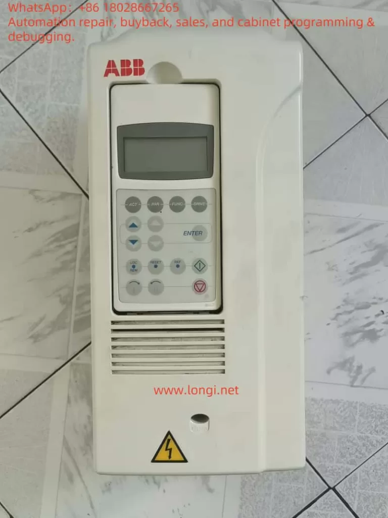
  • User-Friendly: Equipped with a simple operation panel, it supports various parameter settings and real-time monitoring, facilitating user operation and maintenance.

The VCD-2000 series is widely used in industrial scenarios such as constant pressure water supply, wire-cutting machines, and central air conditioning systems. However, even high-performance equipment may trigger fault codes due to external or internal factors, such as E-30.

The Role of VFD Fault Codes

VFD fault codes are an internal diagnostic system of the device, used to issue warnings to users when abnormal conditions are detected. These codes usually correspond to specific fault types, such as overcurrent, overvoltage, overheating, or module failure. By displaying fault codes, the VFD can:

  • Quickly Locate Problems: Help users or technicians identify the cause of the fault promptly.
  • Reduce Downtime: Shorten the troubleshooting and repair time through clear error prompts.
  • Protect Equipment: Trigger protection mechanisms to prevent the fault from escalating and protect the VFD and connected equipment.

For the Andap VCD-2000 series VFD, the E-30 fault code is closely related to the protection mechanism of the power module, indicating that the device has detected an abnormality that may cause serious damage.

Meaning of the E-30 Fault Code

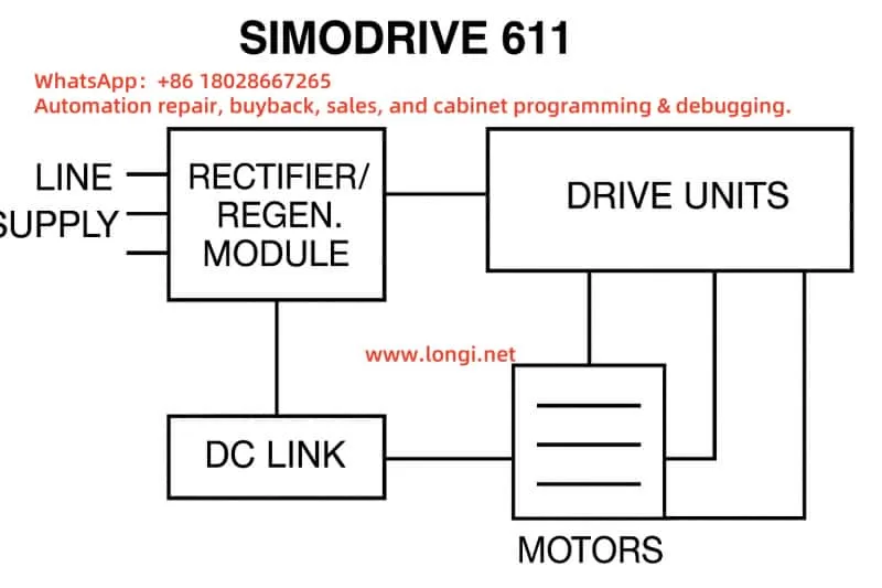
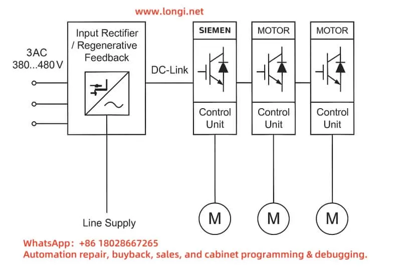
The E-30 fault code represents “Module Drive Protection”. According to the provided documentation, E-30 is triggered when the VFD detects a possible short circuit during the power module drive process. The power module is the core component of the VFD, responsible for converting DC power to AC power to drive the motor. If a short circuit occurs within the module or in the external circuit, it may cause the module to overheat or be damaged. Therefore, the VFD will immediately stop operating and display the E-30 code.

Possible causes of “Module Drive Protection” triggering include:

  • Internal Short Circuit in the Power Module: Damage to IGBTs or other components within the module, leading to a short circuit.
  • External Circuit Short Circuit: Short circuits in the motor coil, connecting cables, or connectors.
  • Abnormal Drive Circuit: Signal abnormalities in the module drive circuit, leading to a false short circuit detection.

Troubleshooting and Solutions for E-30 Fault

When the Andap VCD-2000 series VFD displays the E-30 fault, users can follow these steps for troubleshooting and resolution:

Step 1: Check for Output Short Circuit

  • Operation: Disconnect the VFD from the load (motor) to ensure the VFD is in a no-load state.
  • Test: Attempt to start the VFD and observe if the E-30 fault still appears.
  • Judgment:
    • If the fault disappears, the problem may lie with the motor or the connecting circuit.
    • If the fault persists, the problem may be inside the VFD.
  • Note: Check the motor coil, cables, and connectors for signs of burning, damage, or poor insulation.

Step 2: Check the External Circuit

  • Operation: If the fault disappears in the no-load state, further check the external circuit.
  • Method:
    • Use a multimeter to measure the resistance of the motor coil to confirm if there is a short circuit.
    • Check the connecting cables for damage, aging, or insulation layer peeling.
    • Ensure the connectors are secure, with no looseness or corrosion.
  • Judgment:
    • If a short circuit is found, repair or replace the damaged components.
    • If the external circuit is normal, proceed to the next step.

Step 3: Test and Replace the Motor

  • Operation: Connect a known normal motor to the VFD.
  • Test: Start the VFD and observe if the E-30 fault still occurs.
  • Judgment:
    • If the fault disappears, the original motor may have problems and requires further inspection or replacement.
    • If the fault persists, the problem may be inside the VFD.

Step 4: Check the Internal Module of the VFD

  • Operation: If the above steps cannot solve the problem, check the power module inside the VFD.
  • Method:
    • Contact professional technicians or the Andap official service center to use professional equipment to detect the power module.
    • If the module is damaged, it may need to be replaced or the entire VFD may need to be replaced.
  • Note: The power module involves high-voltage circuits. Non-professional personnel should not attempt to disassemble or repair it to avoid electric shock or further damage to the equipment.

Step 5: Refer to the User Manual

  • Operation: Consult the user manual of the Andap VCD-2000 series VFD to find detailed descriptions of the E-30 fault.
  • Suggestion: The manual usually contains a fault code table and model-specific troubleshooting steps, which may provide additional parameter adjustment suggestions.

Step 6: Contact Technical Support

  • Operation: If the above steps cannot solve the problem, contact the company’s technical support or authorized service provider.
  • Provide Information:
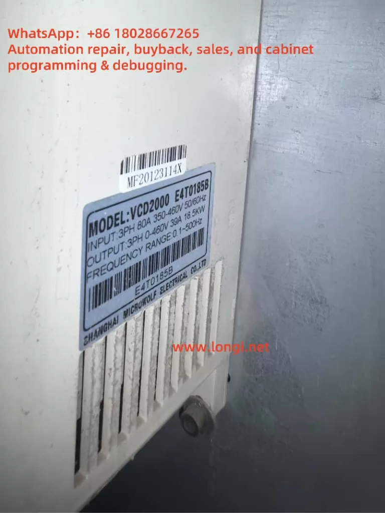
    • VFD model (e.g., VCD2000-A2S0007B).
    • Fault code (E-30).
    • Operating conditions when the fault occurred (e.g., load type, ambient temperature).
    • Troubleshooting steps already attempted.
  • Reference: You can contact us for support.
vcd2000
_cuva

Preventive Measures for E-30 Fault

To reduce the occurrence of the E-30 fault, users can take the following preventive measures:

  • Regular Connection Checks: Inspect the motor and VFD connecting cables monthly to ensure no looseness, damage, or corrosion.
  • Maintain a Good Environment: Install the VFD in a dry, well-ventilated area, avoiding high temperatures (>40℃) or dusty environments.
  • Load Management: Ensure the motor power matches the VFD’s rated power to avoid overloading.
  • Regular Maintenance: Clean the heat sink, check the insulation performance, and update the firmware version according to the manufacturer’s recommendations.
  • Firmware Updates: Check for new firmware versions and upgrade to optimize protection mechanisms and performance.

Conclusion

The E-30 fault code of the Andap VCD-2000 series VFD indicates that the power module drive protection has been triggered, usually caused by internal or external short circuits. Through systematic troubleshooting, including checking for output short circuits, testing the motor, and inspecting the internal module, users can effectively locate the problem and take appropriate measures. Regular maintenance and proper use are key to preventing such faults and ensuring the long-term stable operation of the VFD. If the problem is complex, it is recommended to contact professional technical support promptly to avoid further damage to the equipment.

Fault Troubleshooting Flow Chart

StepOperationJudgmentNext Action
1. Check OutputDisconnect the load and start the VFDFault disappears: External problem; Fault persists: Internal problemCheck the motor and cables
2. Check External CircuitUse a multimeter to check the motor and cablesShort circuit found: Repair; No short circuit: ContinueReplace and test the motor
3. Replace MotorConnect a normal motor and startFault disappears: Original motor problem; Fault persists: VFD problemCheck the power module
4. Check ModuleContact professionals to detect the moduleModule damaged: Replace; Module normal: Check the drive circuitContact technical support
5. Refer to ManualView the user manualSpecific instructions found: Follow the suggestionsContact technical support
6. Contact SupportProvide fault detailsObtain professional guidanceRepair according to the guidance
Posted on

Siemens G120C Inverter F30004 Fault: Analysis and Troubleshooting Strategies


1. Fault Definition and Background

The “F30004” fault is a common error code in the SINAMICS G120C series of Siemens inverters. It indicates:

  • Power unit: Overtemperature heatsink AC inverter

In other words, the temperature of the power module’s heatsink has exceeded the permissible threshold. When the heatsink temperature reaches a warning level (typically around 5°C below the fault threshold), the inverter will raise an alarm (A05000). If the temperature continues to rise, it will escalate into fault F30004, leading to an immediate shutdown.

FAULT 0.F30004

2. Possible Causes of F30004

Based on official documentation and field experience, the core causes of F30004 can be categorized as:

  1. Cooling Fan Failure
    • Internal fans may become jammed, damaged, or run at reduced speed, preventing effective heat dissipation.
  2. Blocked or Poor Heatsink Ventilation
    • Dust accumulation or airflow obstruction can significantly reduce the cooling capacity of the heatsink.
  3. High Ambient Temperature
    • According to the manual, the intake air temperature for air-cooled drives should not exceed 42°C. Exceeding this temperature will increase thermal stress.
  4. Overload or High System Load
    • The drive may be continuously running at high torque or with excessive mechanical load, leading to heat buildup in the power module.
  5. Excessively High Pulse Frequency (Switching Frequency)
    • While high switching frequency improves output wave quality, it also increases internal power loss and heating.
  6. Sensor or Parameter Issues
    • Although rare, a malfunctioning temperature sensor or incorrect settings may lead to false overheating detection.

G120C

3. Diagnostic Steps for F30004

Upon encountering an F30004 fault, follow this step-by-step diagnostic procedure:

1. Check for Preceding Warnings

Use the BOP/IOP panel or engineering software to check if warning A05000 appeared before the F30004 fault. This can confirm if the fault was due to gradual overheating rather than an instant anomaly.

2. Inspect the Cooling Fan

  • Listen for fan noise or visually inspect fan rotation.
  • Remove the fan to check for blockages or dust.
  • Replace the fan module if it shows signs of failure or aging.

3. Evaluate Ambient and Ventilation Conditions

  • Measure the internal cabinet or intake air temperature.
  • Clean all dust and obstruction near the heatsink or vent path.
  • Improve ventilation or consider adding a cabinet cooling fan or air conditioning unit if needed.

4. Check Load Conditions

  • Verify whether the motor is running with excessive load or mechanical resistance.
  • Inspect parameter settings such as p0640 or p1341 (current limits).
  • If operating near thermal limits for extended periods, reduce load or increase cooldown intervals.

5. Reduce Pulse Frequency

  • Use parameter p1800 to lower the switching frequency.
  • Avoid unnecessarily high values that can accelerate heat generation.

6. Validate Temperature Sensor

  • Read diagnostic values such as r2124 and r0037.
  • Replace the sensor or disable overheating fault response if the sensor is faulty.

4. Solutions and Preventive Measures

4.1 Immediate Fixes

  • Let the inverter cool down before clearing the fault.
  • Verify all hardware and environmental factors before restarting.
  • Reset the fault using the control panel or via software tools.

4.2 Long-Term Prevention

  1. Routine Maintenance
    • Clean the inverter regularly, especially the heatsink, fan blades, and air filters.
  2. Temperature Monitoring and Thermal Management
    • Install a cabinet temperature sensor and configure automatic cooling triggers.
  3. Fan Replacement Strategy
    • Implement predictive maintenance based on fan usage hours or set a replacement schedule.
  4. Optimize Load and Parameters
    • Avoid long-term high torque operations.
    • Set appropriate acceleration/deceleration times.
  5. Adjust Switching Frequency Wisely
    • Do not set p1800 too high unless required by motor or application.
  6. Configure Redundant Monitoring (if applicable)
    • Some models support backup temperature detection or allow disabling fault response under certain safety-controlled conditions.

6SL3210-1KE28-4UB1

5. Conclusion and Insights

The F30004 fault in SINAMICS G120C is essentially a protective shutdown triggered by thermal overload. It’s often the result of long-term thermal stress rather than sudden failure. The key principles in addressing it are:

  • Diagnose Systematically: Start from fan, environment, load, parameters, and sensors.
  • Recover Cautiously: Clear the fault only after ensuring proper cooling and safe conditions.
  • Prevent Proactively: Use regular maintenance, parameter tuning, and environmental control.

Unlike faults caused by short circuits or ground failures, thermal faults may seem benign at first, but repeated F30004 events can severely degrade inverter life or lead to power module damage. Preventive measures and automated monitoring are essential to ensure long-term reliable operation.


6. Additional Recommendations

  1. Install a temperature probe in the cabinet to monitor in real-time;
  2. Activate pre-warning thresholds to raise an alarm before reaching F30004;
  3. Monitor for F30035 (intake overtemperature) as it often occurs alongside F30004;
  4. Entrust trained professionals to replace internal fans or disassemble power modules.

This in-depth analysis of fault code F30004 aims to help users not only resolve current errors but also establish best practices in long-term inverter maintenance. For advanced technical assistance, consult Siemens’ certified support service.


Posted on

Comprehensive Guide to Resolving the FF30 Warning “ID MAGN REQ” for ABB ACS800 Inverters

Introduction: Overview of ABB ACS800 Inverters

The ABB ACS800 series of inverters are high-performance industrial devices widely used in manufacturing, mining, water treatment, and other industries. Their core advantage lies in Direct Torque Control (DTC) technology, which enables precise speed and torque control, making them suitable for various complex applications. However, during operation, users may encounter the FF30 warning “ID MAGN REQ,” a common prompt indicating the need for motor identification and magnetization. This article delves into the meaning, causes, and solutions for the FF30 warning, providing detailed operational steps to help users resolve the issue promptly.

WARNING FF30

Meaning of the FF30 Warning “ID MAGN REQ”

The FF30 warning “ID MAGN REQ” indicates that the inverter needs to identify and magnetize the connected motor. Motor identification is a process where the inverter measures the motor’s electrical characteristics (such as resistance and inductance) to establish an accurate model. This model is crucial for DTC control, ensuring efficient and precise motor operation.

The warning typically appears in the following scenarios:

  • Initial Startup: After entering motor data in parameter group 99 (Startup Data), the inverter prompts for identification.
  • Motor Switching: When using user macros to switch between different motors, the inverter requires re-identification of the new motor.

According to the manual, the FF30 warning is a normal part of the startup process, prompting the user to select an identification method: ID Magnetisation or ID Run.

Importance of Motor Identification

Motor identification plays a vital role in inverter operation with the following key functions:

FunctionDescription
Precise ControlEnsures the inverter adjusts control parameters based on the motor’s actual characteristics, achieving accurate speed and torque control.
Efficient OperationOptimizes motor efficiency, reducing energy consumption.
Motor ProtectionSets appropriate protection limits to prevent overcurrent, overheating, and other faults, extending motor life.
Support for Special ApplicationsEnables stable performance in applications requiring zero-speed operation or high torque without speed feedback.

Motor identification is crucial for ensuring system performance and reliability, especially in ACS800 inverters using DTC control.

Possible Causes of the FF30 Warning

The FF30 warning may be triggered by the following reasons:

  • Incomplete Motor IdentificationID Magnetisation or ID Run not performed after initial startup or motor switching.
  • Incorrect Motor Parameters: Motor data in parameter group 99 (such as rated voltage, current, frequency) does not match the motor nameplate.
  • Wiring Issues: Loose or damaged connections between the motor and the inverter.
  • User Macro Switching: Re-identification required after switching user macros in multi-motor applications.
ACS800

Detailed Steps to Resolve the FF30 Warning

Below are the two primary methods for resolving the FF30 warning: ID Magnetisation and ID Run, along with handling multi-motor scenarios using user macros.

Method 1: ID Magnetisation (Motor Magnetization Identification)

Overview: ID Magnetisation is the process of magnetizing the motor at zero speed, lasting 20–60 seconds, suitable for most applications. It is automatically performed during the inverter’s initial startup.

Operational Steps:

  1. Check Motor Parameters:
    • 99.04: Motor rated voltage
    • 99.07: Motor rated current
    • 99.06: Motor rated frequency
    • 99.08: Motor rated power
    • If parameters are incorrect, adjust and save.
    Enter parameter group 99 and verify that the following parameters match the motor nameplate:
  2. Switch to Local Control Mode:
    • Press the LOC/REM key on the control panel until the display shows “L” (Local Control Mode).
  3. Initiate Magnetization Identification:
    • Press the Start key; the inverter begins magnetizing the motor.
    • The process lasts 20–60 seconds, during which the display may show relevant warnings.
  4. Confirm Completion:
    • After identification, the display shows “ID DONE,” and the FF30 warning disappears.

Method 2: ID Run (Motor Running Identification)

Overview: ID Run is a more advanced identification method suitable for applications requiring high-precision control, such as zero-speed operation or high torque without speed feedback. ID Run comes in two types:

  • STANDARD ID Run: Requires the drive mechanism to be disconnected from the motor, allowing the motor to run freely.
  • REDUCED ID Run: Suitable for scenarios where the drive mechanism cannot be disconnected, with slightly lower accuracy.

Operational Steps:

  1. Check Prerequisites:
    • Refer to the ABB ACS800 firmware manual to ensure that ID Run parameter requirements (such as motor stoppage, load conditions) are met.
  2. Set Parameter 99.10:
    • STANDARD: For scenarios where the load can be disconnected.
    • REDUCED: For scenarios where the load cannot be disconnected.
    Enter parameter group 99 and set 99.10 to “STANDARD” or “REDUCED”.
  3. Switch to Local Control Mode:
    • Press the LOC/REM key to display “L”.
  4. Initiate ID Run:
    • Press the Start key; the inverter begins running identification.
    • The display may show warnings such as “MOTOR STARTS” or “ID RUN”.
  5. Confirm Completion:
    • After identification, the display shows “ID DONE,” and the FF30 warning disappears.

Method 3: Handling Multi-Motor Applications with User Macros

In multi-motor applications, user macros can store parameters for different motors, simplifying the switching process.

Operational Steps:

  1. Save Motor Parameters:
    • After completing identification for one motor, set parameter 99.02 to “USER 1 SAVE” or “USER 2 SAVE” to save the parameters.
    • The saving process takes 20–60 seconds.
  2. Switch Motors:
    • Perform identification (ID Magnetisation or ID Run) for the new motor.
    • Save the new motor parameters to another user macro slot.
  3. Load Parameters:
    • Load the corresponding motor parameters by setting 99.02 to “USER 1 LOAD” or “USER 2 LOAD”.
    • Loading may trigger the FF30 warning again, requiring re-identification.

Troubleshooting and Precautions

If the FF30 warning persists, try the following troubleshooting steps:

IssueTroubleshooting Method
Incorrect Motor ParametersRecheck parameter group 99 to ensure it matches the motor nameplate.
Wiring IssuesInspect the cable between the motor and the inverter to ensure connections are secure and undamaged.
Transient FaultTurn off the inverter power, wait a few minutes, and restart.
Firmware IssuesCheck for available firmware updates on the ABB official website.
Complex Application ScenariosContact ABB technical support, providing the inverter model, firmware version, and application details.

Precautions:

  • Always follow electrical safety norms; disconnect power before checking wiring.
  • Ensure the motor and load are in a safe state when performing ID Run.
  • Confirm parameter settings are correct before saving user macros to avoid overwriting important data.

Conclusion

The FF30 warning “ID MAGN REQ” is a common prompt during the normal startup or motor switching process of ABB ACS800 inverters. By performing ID Magnetisation or ID Run, users can quickly resolve the warning, ensuring optimal performance of the inverter and motor. Motor identification not only eliminates the warning but also optimizes control precision, efficiency, and equipment protection. In multi-motor applications, user macros provide a convenient switching solution. If the issue persists, referring to the official manual or contacting ABB support is advisable.

By correctly understanding and addressing the FF30 warning, users can fully leverage the potential of the ACS800 inverter, providing stable and efficient power support for industrial applications.

Posted on

ACS800 Inverter Fault Code 7510: Causes, Diagnosis, and Solutions

Introduction

The ABB ACS800 series inverters are widely used in industrial control applications, providing reliable AC drive solutions for various conditions, including induction and synchronous motor control. Known for their high power density, advanced harmonic suppression, extensive programmability, and modular design, the ACS800 series excels in industries such as process manufacturing, metal processing, mining, cement production, power generation, chemicals, oil and gas, and even special applications like offshore supply vessels. However, in practical use, the ACS800 inverters may encounter faults, with fault code 7510 being a common communication-related issue. This article provides a comprehensive exploration of fault code 7510, including its meaning, potential causes, diagnostic steps, solutions, and preventive measures to guide users effectively.

fault 7510

Overview of the ACS800 Inverter

The ACS800 series from ABB is a high-performance AC drive designed to meet the needs of a wide range of applications, from small equipment to large industrial systems. Its key features include:

  • High Power Density: Delivers high output power in a compact form, ideal for space-constrained environments.
  • Harmonic Suppression: Utilizes advanced technology to reduce harmonic interference, enhancing power quality.
  • Extensive Programmability: Offers a rich set of parameters and control options for customized applications.
  • Modular Design: Facilitates easy installation, maintenance, and upgrades, reducing operational costs.

The ACS800 inverter is commonly deployed in scenarios requiring precise motor control, such as assembly lines, pump stations, and fan systems. However, communication issues remain a potential challenge, with fault code 7510 being a notable example.

Meaning of Fault Code 7510

In the ACS800 inverter, fault code 7510 typically indicates a “COMM MODULE FAULT.” This fault suggests a periodic loss of communication between the inverter and its main controller, such as a PLC or DCS. Such a disruption can prevent the inverter from receiving control commands or transmitting status updates, severely affecting system operation.

According to official documentation, the 7510 fault is associated with the communication module and is often triggered by programmable fault functions (parameters 30.18 and 30.19). The communication module serves as the bridge between the inverter and external control systems, handling data exchange and synchronization. Any malfunction in this module can compromise the entire system’s performance.

Analysis of Potential Causes

Fault code 7510 can stem from various factors. Below is a detailed analysis of common causes:

CategorySpecific IssueDescription
Communication Connection IssuesDamaged or loose cablesPhysical damage, aging, or poor connections can interrupt signals.
Excessive cable lengthCable length exceeding protocol specifications (e.g., Modbus max of 1200 meters) may cause signal loss.
Poor connector contactImproperly installed or corroded connectors.
Parameter Setting ErrorsMismatched communication protocolInconsistent settings (e.g., baud rate, data bits, stop bits) with the main controller.
Address conflictsInverter address clashes with other devices in the system.
Improper timeout settingsToo short a timeout period may trigger faults under network load.
Fieldbus Configuration ErrorsIncorrect configuration fileErrors in the fieldbus configuration file (e.g., GSD file).
Termination resistor issuesMissing or incorrect termination resistors causing signal reflection.
Fieldbus power problemsUnstable or interrupted fieldbus power supply.
Main Controller IssuesConfiguration errorsIncorrect main controller setup unable to recognize the inverter.
Software incompatibilityMismatched software versions between the controller and inverter.
Hardware failureDamaged controller hardware affecting data transmission.
Inverter Internal FaultsCommunication module failureHardware damage or aging of the communication module.
Firmware issuesIncompatible or buggy firmware versions.

Diagnostic Steps

When the ACS800 inverter displays fault code 7510, follow these systematic diagnostic steps to identify the root cause:

  1. Inspect Communication Cables:
    • Check for physical damage such as cuts or wear.
    • Ensure all connectors are secure and free from corrosion or dust.
    • Verify that cable length complies with protocol specifications.
  2. Verify Parameter Settings:
    • Access the inverter’s parameter menu and review group 51 (COMM MODULE DATA for fieldbus adapter) or group 52 (STANDARD MODBUS for Modbus links).
    • Confirm that baud rate, data bits, stop bits, and other settings match the main controller.
    • Check fault function parameters (e.g., 30.18, 30.19) for correct configuration.
  3. Check Fieldbus Status:
    • For fieldbus systems (e.g., Profibus, DeviceNet, or ControlNet), refer to the relevant fieldbus adapter manual.
    • Use diagnostic tools to monitor communication status and detect packet loss or errors.
    • Ensure termination resistors are correctly set (typically 120 ohms) and power supply is stable.
  4. Restart the System:
    • Power off the inverter and main controller, wait a few minutes, then restart.
    • Observe if the fault clears, ruling out temporary issues.
  5. Inspect the Main Controller:
    • Confirm the main controller is properly configured to communicate with the inverter.
    • Review controller logs for communication-related errors.
    • Ensure software compatibility between the controller and inverter.
  6. Replace the Communication Module:
    • If all else fails, the communication module may be faulty.
    • Before replacement, ensure compatibility with the inverter’s firmware and involve a qualified technician.
ACS800

Solutions

Based on the diagnosis, implement the following targeted solutions:

  • Fix Communication Connections:
    • Replace damaged cables with those meeting specifications.
    • Re-secure loose connectors and clean any corrosion or debris.
  • Correct Parameter Settings:
    • Adjust group 51 or 52 parameters to align with the main controller’s configuration.
    • Increase communication timeout settings (e.g., parameters 30.18 or 30.19) to accommodate network load.
  • Reconfigure the Fieldbus:
    • Verify and correct the fieldbus configuration file.
    • Set proper termination resistors and check for power stability.
    • Eliminate interference from other devices.
  • Address Main Controller Issues:
    • Update the main controller software to the latest version for compatibility.
    • Correct configuration errors such as address or protocol settings.
    • Replace damaged controller hardware if necessary.
  • Replace the Communication Module:
    • Contact ABB technical support or a professional to replace a defective module.
    • Reconfigure parameters and test communication post-replacement.

Case Studies

Here are two real-world examples illustrating the diagnosis and resolution of 7510 faults:

  1. Case 1: Interference in a ControlNet System
    In a ControlNet-based system, the ACS800 inverter intermittently triggered a 7510 fault. Investigation revealed that another device was sending erroneous data packets, disrupting communication. Isolating the device and rescheduling network connections resolved the issue.
  2. Case 2: Incorrect Parameter Settings
    In a Modbus system, a 7510 fault occurred due to an excessively short timeout setting, causing failures under network load. Adjusting parameter 30.18 to extend the timeout restored normal communication.

These cases highlight the need to consider hardware, software, and network factors when resolving 7510 faults.

Preventive Measures

To minimize the occurrence of 7510 faults, users can adopt the following preventive strategies:

  1. Regular Connection Checks:
    • Inspect communication cables and connectors monthly for damage or looseness.
    • Clean connectors to prevent dust or corrosion buildup.
  2. Backup Parameter Settings:
    • Regularly save inverter and controller parameter settings in a secure location.
    • Maintain backups before equipment replacement or firmware updates.
  3. Keep Systems Updated:
    • Periodically check for the latest inverter firmware and controller software.
    • Ensure all component versions are compatible.
  4. Train Operators:
    • Provide training on inverter operation, parameter settings, and basic troubleshooting.
    • Familiarize staff with relevant manual sections.
  5. Implement Monitoring Systems:
    • Use software to monitor communication status and fault alerts in real time.
    • Set up automatic notifications for prompt response to issues.

These measures can significantly enhance system reliability and reduce downtime.

Conclusion

Fault code 7510 in the ACS800 inverter is a common communication module issue, potentially caused by cable problems, parameter errors, fieldbus misconfiguration, or hardware failures. Through systematic diagnostic steps—such as cable inspection, parameter verification, and fieldbus reconfiguration—along with targeted solutions like repairs, adjustments, or module replacement, users can effectively resolve the fault. Coupled with preventive actions like regular maintenance, parameter backups, and operator training, these strategies ensure long-term system stability. This article aims to provide clear, practical guidance for addressing ACS800 inverter 7510 faults.

References

Posted on

User Guide for MyGo Pro PCR Instrument

1. Principles, Functions, and Applications of MyGo Pro PCR Instrument

Principles

The MyGo Pro is a real-time quantitative PCR (qPCR) instrument based on the polymerase chain reaction (PCR) technology, enabling DNA or RNA amplification through thermal cycling. Its core technology is “Full Spectrum Optics,” which utilizes high-intensity LEDs (500 nm excitation) and a CMOS camera (510-750 nm detection) to collect fluorescence data from 120 optical channels in parallel from each reaction tube without moving parts, ensuring the reliability of multiplex PCR. Additionally, the MyGo Pro supports high-resolution melt (HRM) curve analysis, capable of distinguishing all types of single nucleotide polymorphisms (SNPs), including Class 4 SNPs.

MYGO PRO qPCR

Functions

The MyGo Pro offers the following key functions:

  • High Precision and Sensitivity: Single-copy detection, 9-log dynamic range, and 1.1-fold discrimination precision.
  • Multiplex PCR: Supports simultaneous analysis of at least 7 targets, each using a different fluorescent label.
  • Fast Thermal Cycling: Heating speed of 5°C/second, cooling speed of 4°C/second, with 45 cycles completed in approximately 33 minutes and total run time less than 40 minutes.
  • HRM Analysis: Efficiently distinguishes genetic variations by combining thermal control, optical data quality, and HRM data analysis.
  • Automated Analysis: Software supports absolute and relative quantification, melt curve analysis, endpoint genotyping, and HRM.

Technical Specifications

  • Thermal Uniformity: ±0.1°C
  • Thermal Accuracy: ±0.25°C
  • Temperature Range: 37-99°C
  • Optical Channels: 4 (for multiplexing), supporting 22 pre-calibrated dyes including SYBR Green I, FAM, ROX, etc.
  • Supported Detection Formats: TaqMan, Molecular Beacons, SimpleProbes®, Intercalators, HRM

The following table summarizes the main functions:

Function CategoryDetails
Detection SensitivitySingle-copy detection, 9-log dynamic range, 1.1-fold discrimination precision
Thermal Cycling SpeedHeating 5°C/second, cooling 4°C/second, 45 cycles in ~33 minutes
Optical System120 optical channels, 510-750 nm detection, CMOS camera
Supported DyesSYBR Green I, FAM, ROX, etc. (22 types)
Analysis ModulesAbsolute/relative quantification, melt curve, HRM, etc.

Applications

The MyGo Pro is widely used in:

  • Gene Expression Analysis: Detects 10% differences in transcript concentrations.
  • Pathogen Detection: Quantifies pathogen levels.
  • Genetic Variation Analysis: Identifies SNPs through HRM.
  • Laboratory Research: Suitable for life sciences, food species identification, virus detection, etc.
  • High-Throughput Applications: A single computer can control 200 MyGo Pro or 400 MyGo Mini instruments.

2. Installation and Setup Process for MyGo Pro PCR Instrument

Installation Steps

  1. Check Components:
    • Verify that the package includes: MyGo Pro qPCR system, user manual, power adapter and cables, Ethernet cable, USB drive.
    • Check for any damage or missing parts.
  2. Connect Power:
    • Use a 24V DC power adapter with a 3-pin IEC connector.
    • The instrument has no power switch; an optional switchable cable can be purchased.
  3. Choose Connection Method:
    • USB: Use a MyGo-branded USB drive containing software and manuals. Third-party USBs must pass a software speed test.
    • Ethernet: Connect to a LAN or directly to a computer.
  4. Software Installation:
    • Download the MyGo software from the USB drive or online.
    • Compatible with Windows, Mac OS X, and Linux; no license restrictions.
  5. Environment Setup:
    • Place the instrument on a stable, dry laboratory bench, away from drafts.
    • Ensure ventilation ports are clear and not covered.
    • The heated lid reaches 105°C during experiments; do not touch after use.

Setup Notes

  • Ventilation: Do not place items or liquids on the heated lid to avoid performance issues.
  • Environmental Conditions: Refer to the user manual for operating, transport, and storage conditions.
  • Transport: Use a flight case or original packaging with polystyrene rings to protect the wells.

The following table summarizes the installation steps:

StepDetails
Check ComponentsVerify instrument, power adapter, cables, USB drive, etc.
Connect PowerUse 24V DC power, 3-pin IEC connector
Connection MethodUSB or Ethernet; USB must pass speed test
Software InstallationDownload online, compatible with multiple platforms
Environment SetupStable bench, away from drafts, ensure ventilation
MYGO PRO qPCR

3. Connection and Experimental Operation Methods for MyGo Pro PCR Instrument

Connection Methods

  1. USB Connection:
    • Insert a MyGo-branded USB drive containing experimental files.
    • Use a USB extension cable (for MyGo Mini).
  2. Ethernet Connection:
    • Connect using an Ethernet cable to a LAN or computer.
    • Ensure network settings are correct to avoid data loss.

Experimental Operation Steps

  1. Prepare Samples:
    • Use 0.1 ml tubes or 8-tube strips, with a maximum of 32 samples and reaction volumes of 10-100 μl.
    • When running a single 8-tube strip, load empty strips in rows 1 and 4.
  2. Set Up Experiment:
    • Create a template in the MyGo software: Click “Open” and select the “Template” file type.
    • Set up sample and target information; modifications can be made during the experiment.
    • Configure thermal cycling parameters (e.g., hold times, cycle numbers).
  3. Start Experiment:
    • Initiate via USB or LAN; settings cannot be changed once the experiment starts.
    • The lid automatically locks and unlocks after the experiment (indicated by cyan color).
  4. Monitor Experiment:
    • The software displays real-time temperature and fluorescence data.
    • Background correction: Automatically performed after 6 cycles (based on the average of cycles 4, 5, and 6).
  5. Save Data:
    • Save to PC or USB drive; ensure stable network for LAN connections.

Notes

  • Consumables: Use airtight, optically transparent consumables.
  • Dyes: Pre-calibrated for 22 dyes (e.g., FAM, ROX); generate dye files for non-pre-calibrated dyes.
  • Data Management: Use a USB drive to reduce data loss due to network instability.

The following table summarizes the experimental operation steps:

StepDetails
Sample Preparation0.1 ml tubes or 8-tube strips, 10-100 μl reaction volumes
Experiment SetupCreate template, set sample and target info, configure thermal cycling
Start ExperimentInitiate via USB or LAN; lid automatically locks
Data MonitoringView real-time temperature and fluorescence data, automatic background correction
Data SavingSave to PC or USB; ensure stable network for LAN

4. Tips and Tricks for Using MyGo Pro PCR Instrument

Tips

  1. Consumable Selection:
    • Use MyGo-recommended consumables to ensure sealing and heat transfer efficiency.
    • Third-party consumables must be airtight, optically transparent, biocompatible, and DNA/RNA enzyme-free.
  2. Sample Handling:
    • Ensure tube caps are properly sealed to prevent leakage.
    • Wear gloves during operation and immediately dispose of used PCR tubes after the experiment to prevent contamination.
  3. Experiment Optimization:
    • Use non-fluorescent quenchers (e.g., BHQ) for optimal fluorescence signals.
    • Add fluorescent quenchers (e.g., TAMRA) to sample settings to enable spectral deconvolution.
  4. Software Usage:
    • Use templates to quickly start experiments.
    • Regularly check for software updates.

Maintenance Suggestions

  1. Cleaning:
    • Refer to the decontamination guide if the instrument is dirty or contaminated.
    • Ensure the instrument is clean before sending it for repair.
  2. Calibration:
    • No regular optical or thermal calibration is required; contact technical support if damaged.
  3. Transport:
    • Minimize movement; use polystyrene rings to protect the wells and a flight case or original packaging.

The following table summarizes the tips:

CategoryTips
Consumable SelectionUse MyGo-recommended consumables; ensure sealing and optical transparency
Sample HandlingSeal tube caps, wear gloves, dispose of used PCR tubes immediately
Experiment OptimizationUse non-fluorescent quenchers, add fluorescent quenchers to sample settings
MaintenanceRegularly clean, no regular calibration needed, transport safely

5. Common Troubleshooting Methods for MyGo Pro PCR Instrument

Common Problems and Solutions

  1. Instrument Does Not Power On:
    • Check if the power cable is securely connected to the instrument and outlet.
  2. Experiment Fails to Start:
    • Ensure tubes are properly loaded and the MyGo Mini lid is securely closed.
    • Check network settings (for LAN operation).
  3. Network Connection Fails:
    • Ensure the Ethernet cable clicks into place when inserted and is not loose when gently pulled.
  4. Experiment Fails to Complete:
    • Do not close the software or disconnect the network during LAN operation.
  5. USB Operation Issues:
    • Ensure the USB drive is securely connected and contains experimental files.
    • Do not remove the USB before the experiment completes (MyGo Pro indicates cyan color).
  6. Instrument Flashes Red:
    • Power on the instrument; if it continues to flash, contact technical support.

Other Notes

  • Data Loss: Use a USB drive if the LAN is unstable.
  • Contamination: Refer to the decontamination guide to clean the instrument.

The following table summarizes the troubleshooting methods:

ProblemSolution
Instrument Does Not Power OnCheck power cable connection
Experiment Fails to StartConfirm tube loading, check network settings
Network Connection FailsEnsure Ethernet cable is securely connected
USB Operation IssuesConfirm USB drive connection, do not remove prematurely
Flashing RedPower on; if persistent, contact technical support

Summary

The MyGo Pro PCR instrument is an efficient and reliable qPCR system suitable for various molecular biology applications. Its Full Spectrum Optics and fast thermal cycling technology ensure high precision and multiplex analysis capabilities. Installation and setup are straightforward, and experimental operations are completed through user-friendly software. Following usage tips and maintenance suggestions ensures optimal performance, and common issues can be resolved by checking connections and settings.

Posted on

Technical Guide for ebm-papst RG148 Series (1200-3633 EC) Fans: Working Principles, Wiring, Commissioning, and Troubleshooting


1. Product Overview and Working Principle

The RG148 series from ebm-papst utilizes EC (Electronically Commutated) motor technology, integrating a rectifier, inverter, and a brushless DC (BLDC) motor into a compact unit. Instead of using a traditional AC induction motor and external variable frequency drive (VFD), these fans convert AC mains to DC internally and use an IGBT inverter to generate three-phase PWM signals that drive the motor.

Key Advantages

  • High Efficiency: No belt or rotor copper loss; system efficiency >90%.
  • Brushless & Maintenance-Free: No mechanical commutation—electronic switching replaces brushes.
  • Easy Speed Control: A simple 1–6 kHz PWM or 0–10 V analog input allows linear speed regulation.

These fans are ideal for applications requiring wide speed ranges, low maintenance, and energy savings of up to 30% compared to traditional setups.


 RG148

2. Connector Definitions and Wiring

The fan features a 5-pin control connector alongside L/N/PE power terminals. The connector is typically an AMP MATE-N-LOK or Molex Mini-Fit Jr. housing, with pin numbers (“1–5”) molded into the plastic shell.

PinWire Color (Original Harness)FunctionDescription
1BlueGND (Signal Ground)SELV ground, isolated from chassis
2YellowPWM IN / 0–10 V1–6 kHz square wave; >20% for startup, >5% for run
3N.C. (Not Connected)Reserved
4WhiteTach Out2 pulses/rev, open-collector output
5Brown+18 V OutputMax ~20 mA, for pull-up or optocoupler supply

How to identify pins:

  1. Visually inspect the connector for molded pin numbers or orientation notch.
  2. With power applied, use a multimeter: the only stable ~18 V pair indicates Pin 1 (GND) and Pin 5 (+18 V).
  3. Injecting PWM into Pin 2 should spin the fan—this helps verify its identity.

 RG148  card

3. Minimal Wiring for Testing

Power Side: Connect L/N to 230 V AC (or 115 V for low-voltage variants). Add a 6 A slow-blow fuse. PE must be grounded for safety.

Control Side (minimum 3 wires):

  • Pin 1 → Connect to your microcontroller or function generator GND
  • Pin 2 → Feed a 0–5 V PWM signal through a 1 kΩ resistor
  • Pin 4 / Pin 5 → Optional; leave unconnected during basic testing

Startup Procedure

  1. With the fan powered off, complete wiring.
  2. Power on with PWM = 0%.
  3. Output a 30% duty PWM (e.g. 3 kHz); the fan should spin up smoothly.
  4. Adjust duty cycle and observe speed changes.
  5. Set PWM <3% to stop the fan.

This minimal setup allows safe testing without needing feedback circuits.


4. Tuning Parameters and Performance Verification

ParameterRecommended ValuePurpose
PWM Frequency2–4 kHzAvoids audible noise
Startup Duty≥25%Ensures soft start
Minimum Duty>5%Fan stops below this value
RPM Calculationrpm = freq × 30Based on Tach signal (2 p/rev)

By measuring the Tach frequency and correlating it with airflow or pressure, you can build a duty-RPM-airflow map for system tuning or PID feedback control.


5. Common Faults and Troubleshooting

SymptomPossible CauseCheck / Solution
No rotationPWM <20%; no GND; internal fuse blownOscilloscope on Pin 2; verify Pin 1–5 = +18 V; check fuse
Whining or jitteringPWM freq too low; sharp duty changesSet to 2–4 kHz; ramp the duty smoothly
No Tach pulseMissing pull-up or overvoltagePull up Pin 4 to +18 V with 10 kΩ or use voltage divider
Overheat shutdownPoor ventilation; ambient >60°CClean airflow path; reduce speed/load
EMI interferenceLong unshielded wiresUse shielded twisted pairs; add 100 Ω damping resistors on Pin 2/4

RG148/1200-3633-010204

6. Maintenance and Advanced Configuration

  • Routine Check: Every 3 months, clean the impeller and check grounding screws; test insulation yearly.
  • Cable Management: For >1 m signal wires, use shielded twisted pairs and ground the shield at one end.
  • EEPROM Configuration: Use ebm-papst EC-Control software via Bluetooth or RSB bus to tweak internal parameters (e.g. soft-start ramp, min RPM).
  • Harmonic Filtering: For multiple fans on a shared supply, consider adding filters or 12-pulse rectifiers to reduce THDi.

7. Conclusion

The RG148 EC fan series represents a highly efficient and compact solution for modern ventilation systems. With its integrated inverter and brushless motor, it provides wide-speed-range performance without external VFDs. By mastering the 3-wire minimal control method, understanding PWM tuning, and applying basic troubleshooting, engineers can easily integrate and commission these fans in test setups and production lines. For advanced applications, feedback via Tach signals and EEPROM customization further enhances control accuracy and energy efficiency.

This guide aims to provide a comprehensive, practical overview to help users get the fan up and running safely, optimize its performance, and resolve common issues in real-world scenarios.

Posted on

Control System Design for Packaging Rope Production Line Using Longi Inverters and PLCs

1. Overview and Requirements of the Packaging Rope Production Line

The packaging rope production line is widely used for processing polypropylene (PP) and polyethylene (PE) materials. It primarily involves extrusion, stretching, twisting, and winding to produce the required packaging ropes. The production line involves several motors, heating control, tension control, and synchronization control. The stability and precision of the equipment are critical for production efficiency and product quality.

Main Equipment:

  1. Extruder: Used for melting and extruding the raw material into a uniform melt.
  2. Drawing Machine: Used for stretching the cooled fibers to increase strength and elasticity.
  3. Twisting Machine: Used for twisting the stretched fibers into ropes.
  4. Winding Machine: Used for winding the finished ropes into coils.

Packing rope production line

2. Control System Design

1. Motor Control and Inverter Selection

Motor control is essential for precise production on the line. The speed of each device’s motor must be adjusted in real-time to meet the production process’s requirements. Longi 9000 series inverters will be used to control the speed of each motor.

Extruder Motor Control:
  • Motor Power: Typically, 15-55 kW asynchronous motors are selected.
  • Inverter Model: Longi 9000 series inverters are suitable for high-power motors, providing precise speed control.
  • Wiring Method: The inverter’s input is connected to a three-phase power supply, and the output is connected to the motor terminals via cables, usually using a star connection for stable starting torque and reliability.
Extruder Motor Parameter Settings:
  • Frequency Range: 0-60Hz (can be adjusted depending on production requirements, typically set at 30Hz).
  • Acceleration/Deceleration Time: Set to 5-10 seconds for smooth starting and stopping, avoiding overload.
  • Current Limiting: Set to 120% of rated motor current as protection.
Drawing Machine Motor Control:

The drawing machine is used to stretch the fibers, and its speed is directly linked to the extruder’s output speed. The drawing machine inverter will be synchronized with the extruder inverter.

  • Motor Power: Typically, 5-15 kW asynchronous motors are selected.
  • Inverter Model: Longi 9000 series inverters.
  • Wiring Method: Similar to the extruder inverter, connected via bus for synchronized control.
Drawing Machine Motor Parameter Settings:
  • Frequency Range: 0-100Hz to match stretching speed with the extruder.
  • Acceleration/Deceleration Time: Set to 5-10 seconds to avoid fiber breakage from fast stretching.
  • Speed Synchronization: Use the inverter’s multi-machine synchronization function to keep the drawing machine synchronized with the extruder.
Twisting Machine and Winding Machine Motor Control:

Both the twisting machine and winding machine require precise speed control, especially for tension control under different conditions.

  • Motor Power: Twisting machine typically uses 2-5 kW motors, and winding machine uses 5-15 kW motors.
  • Inverter Model: Longi 9000 series for precise speed regulation and starting/stopping control.
  • Wiring Method: Standard three-phase connection, with the inverter connected to the motor.
Twisting Machine Motor Parameter Settings:
  • Frequency Range: 0-60Hz.
  • Acceleration/Deceleration Time: Set to 3 seconds for smooth twisting.
  • Synchronization Function: Achieved through PLC coordination with the drawing and winding machines.
Winding Machine Motor Parameter Settings:
  • Frequency Range: 0-60Hz, closely related to fiber tension.
  • Acceleration/Deceleration Time: Set to 5 seconds for uniform winding.

Packing rope production line

2. Heating Control System and Temperature Regulation

The heating system in the extruder is crucial for maintaining material quality. Temperature control must be precise. We will use Longi PLC (LX1000 series) along with temperature control modules to monitor and adjust the temperature.

Extruder Temperature Control Design:
  • Heating Zones: The extruder has multiple heating zones, each equipped with a temperature control module to monitor and adjust the temperature.
  • Wiring Method: The temperature control module’s output is connected to the heater, and the PLC adjusts the temperature using analog outputs (4-20mA).
  • Temperature Sensor: Use PT100 sensors with an accuracy of ±0.5°C to provide real-time temperature feedback to the PLC.
Temperature Control Parameter Settings:
  • Set Temperature Range: Typically set at 180-220°C for different zones, suitable for PP and PE melting temperatures.
  • Temperature Adjustment Strategy: Use PLC’s PID control algorithm to maintain precise temperature, avoiding overheating or cooling, which may cause instability in the material quality.

3. Tension Control System

Precise tension control is essential during the drawing and winding processes to prevent fiber breakage or uneven winding. We will integrate tension sensors with the Longi PLC to implement real-time tension monitoring and control.

Tension Control Design:
  • Tension Sensors: Select high-precision tension sensors like the FMS series, installed at key points on the drawing and winding machines for real-time feedback.
  • Control Method: The PLC receives signals from the tension sensors and adjusts the drawing and winding speeds to maintain consistent tension.
  • Wiring Method: The tension sensors provide analog signals to the PLC, which adjusts the motor speeds for closed-loop tension control.
Tension Control Parameter Settings:
  • Target Tension Range: Set between 0.5-2kg to ensure stable fiber stretching and winding.
  • Feedback Method: PLC adjusts the drawing and winding machine speeds based on the tension feedback from sensors.

4. Synchronization Control Scheme

Synchronization control between multiple devices is essential for smooth production. We will use Longi PLC’s high-speed counters and pulse output features to synchronize devices.

Synchronization Control Design:
  • Master and Slave Synchronization: The extruder will be the master device, while the drawing machine, twisting machine, and winding machine will be slaves. The PLC will synchronize these machines via pulse output.
  • Wiring Method: The PLC sends pulse signals to all devices using high-speed counters to synchronize their operation.
  • Synchronization Adjustment: The PLC adjusts each device’s speed according to the main device’s status, ensuring coordinated operation.
Synchronization Control Parameter Settings:
  • Synchronization Pulse Frequency: Set to 50Hz to synchronize all devices.
  • Precision Requirements: The PLC’s pulse output precision is set to 1ms to ensure synchronization accuracy.

Packing Rope Control Cabinet

3. System Architecture and Wiring Diagram

Below is the basic wiring and architecture diagram for the packaging rope production line control system:

Equipment Connection and Wiring Diagram:

[Raw Material Mixer] → [Extruder] → [Cooling Tank] → [Drawing Machine] → [Twisting Machine] → [Winding Machine]
       ↑                ↑                ↑               ↑
       |                |                |               |
   [Longi PLC] ←→ [Longi 9000 Inverter] ←→ [Temperature Control Module] ←→ [Tension Sensors]

System Architecture Diagram:

              +------------+                +-------------+
              |  Longi PLC  | ←--> [Inverter] ←--> [Motor] ←--> [Device]
              +------------+                +-------------+
                     ↑                            ↑
                  [Sensors] ←--> [Tension Control] ←--> [Heating Control]

4. Conclusion

By integrating Longi 9000 series inverters, LX1000 series PLCs, and Longi plastic machine configuration software into the packaging rope production line, we can achieve precise motor control, temperature regulation, tension control, and synchronization control, ensuring efficient and stable production. The design is clear and logically sound, meeting the needs of modern packaging rope production lines for automation and intelligence.


Posted on

Understanding and Resolving the Er.OLL Fault in Hope-130 Variable Frequency Drives

Introduction

Variable Frequency Drives (VFDs), such as the Hope-130 series manufactured by Senlan, are critical components in modern industrial automation, enabling precise control of motor speed and energy efficiency. However, like any sophisticated equipment, VFDs are prone to faults that can disrupt operations if not addressed promptly. One such fault is the “Er.OLL” error code, which signals an overcurrent or overload condition. This article delves into the meaning of the Er.OLL fault, its potential causes, diagnostic methods, and step-by-step solutions to restore normal operation. By understanding this fault, operators can minimize downtime and maintain productivity in their facilities.

ER.OLL

What Does the Er.OLL Fault Mean?

The “Er.OLL” fault code, as indicated on the Hope-130 VFD display, is an alarm triggered by the device’s protective mechanisms when it detects an overcurrent or overload situation. According to the technical manual for the Hope-130 series (referenced on Page 111), this fault, denoted as code 15, is associated with excessive current draw that exceeds the VFD’s rated capacity. Overcurrent can occur when the motor is subjected to a load beyond its design limits, or when electrical issues such as short circuits or insulation failures are present. The fault is designed to protect the VFD and connected motor from damage, but it requires immediate attention to identify and resolve the underlying issue.

Common Causes of the Er.OLL Fault

Several factors can contribute to the Er.OLL fault, ranging from mechanical to electrical and configuration-related issues. Understanding these causes is the first step toward effective troubleshooting:

  1. Excessive Mechanical Load: If the motor is driving a machine with an unusually high load—such as a jammed conveyor belt or a pump handling blocked fluid—the current demand may spike, triggering the fault.
  2. Short Circuit or Ground Fault: Damaged wiring, faulty insulation, or a short circuit between phases can cause an abrupt increase in current, leading to the Er.OLL alarm.
  3. Incorrect VFD Parameter Settings: Misconfigured parameters, such as an improperly set current limit or acceleration/deceleration time, can cause the VFD to misinterpret normal operation as an overload.
  4. Motor Issues: A motor with worn bearings, internal short circuits, or phase imbalances can draw excessive current, prompting the fault.
  5. Power Supply Problems: Voltage fluctuations or an unstable power supply can lead to irregular current flows, potentially triggering the protective mechanism.

Diagnostic Approach

Diagnosing the Er.OLL fault requires a systematic approach to pinpoint the root cause. Here are the steps to follow:

  • Visual Inspection: Begin by checking the motor, wiring, and connected machinery for obvious signs of damage, such as burnt cables, loose connections, or mechanical blockages.
  • Review VFD Display and Logs: The Hope-130 VFD provides fault details on its display. Use the “MENU” and “ENTER” buttons to access fault history and current readings (e.g., A for amperage) to confirm the overcurrent condition.
  • Measure Electrical Parameters: Use a multimeter to check the input voltage and current drawn by the motor. Compare these values against the VFD’s rated specifications.
  • Inspect Motor Operation: Run the motor manually (if safe) to listen for unusual noises or vibrations that might indicate mechanical issues.
  • Check Parameter Settings: Access the VFD’s parameter menu to verify settings such as current limit, overload protection thresholds, and acceleration profiles.

Step-by-Step Solutions

Once the cause is identified, the following solutions can be applied to resolve the Er.OLL fault:

  1. Address Mechanical Overload:
    • If a mechanical blockage is found (e.g., a jammed conveyor), stop the system, clear the obstruction, and restart the VFD.
    • Ensure the load matches the motor’s rated capacity. If the load is consistently high, consider upgrading to a more powerful motor or VFD.
  2. Fix Electrical Faults:
    • Inspect all wiring for signs of damage or short circuits. Replace any faulty cables or connectors.
    • Test for ground faults using an insulation resistance tester. Repair or replace any components with compromised insulation.
  3. Adjust VFD Parameters:
    • Access the VFD’s parameter settings via the control panel. Increase the acceleration/deceleration time to reduce the current spike during startup.
    • Adjust the current limit parameter to align with the motor’s rated current, ensuring it does not exceed the VFD’s capacity.
  4. Service the Motor:
    • If the motor is faulty, disassemble it to check for worn bearings or internal short circuits. Lubricate or replace bearings as needed, and rewind or replace the motor if damage is extensive.
    • Balance the motor phases by checking the resistance of each winding with a multimeter.
  5. Stabilize Power Supply:
    • Install a voltage stabilizer or UPS if power fluctuations are detected. Ensure the power source meets the VFD’s voltage requirements.

After implementing these fixes, reset the fault by pressing the “RESET” button on the VFD panel and attempt to restart the system. Monitor the operation to ensure the fault does not recur.

senlan hope130 iverter

Preventive Measures

To avoid future Er.OLL faults, consider the following preventive strategies:

  • Regular Maintenance: Schedule routine inspections of the VFD, motor, and connected machinery to detect wear or damage early.
  • Proper Installation: Ensure the VFD and motor are installed according to the manufacturer’s guidelines, with adequate ventilation and secure wiring.
  • Training: Train operators to recognize early signs of overload or electrical issues and to use the VFD’s diagnostic features effectively.
  • Load Management: Avoid sudden load changes by implementing gradual startup procedures and ensuring machinery operates within design limits.

Conclusion

The Er.OLL fault in a Hope-130 VFD is a critical alert that demands prompt action to protect equipment and maintain operational efficiency. By understanding its meaning as an overcurrent or overload condition and systematically diagnosing its causes—whether mechanical, electrical, or configurational—operators can apply targeted solutions to resolve the issue. From clearing mechanical blockages to adjusting VFD parameters and servicing the motor, each step contributes to a robust resolution process. Moreover, adopting preventive measures can significantly reduce the likelihood of recurrence, ensuring long-term reliability. With proper care and attention, the Hope-130 VFD can continue to serve as a dependable asset in industrial applications, minimizing downtime and maximizing productivity.

Posted on

Guide to Solving ERR24 Fault on SUNYE CM530/CM530H Inverters

Introduction

Variable Frequency Drives (VFDs), commonly known as inverters, are essential components in modern industrial control systems. They regulate motor speed and performance to achieve energy efficiency and precise control. However, their complexity can lead to faults, which are often indicated by error codes on the inverter’s display. In the SUNYE CM530 and CM530H series inverters, ERR24 is a frequently encountered fault code, typically associated with an “output side phase error” or “output phase loss.” This article provides a comprehensive guide to understanding ERR24, identifying its causes, troubleshooting the issue, and implementing preventive measures to ensure reliable operation.

err24 fault

Understanding ERR24

The ERR24 fault code likely indicates that the inverter has detected an issue with the output side, specifically a phase sequence error or a missing phase in the three-phase output (U, V, W) to the motor. This disruption can prevent the motor from operating correctly, potentially causing equipment downtime or damage. The error suggests an imbalance in the current or voltage output, which is critical for maintaining stable motor performance. Addressing ERR24 promptly is vital to minimizing disruptions in industrial processes.

Possible Causes of ERR24

Several factors may trigger the ERR24 fault code. Based on common inverter issues and general electrical engineering principles, the following are the most likely causes:

  1. Output Cable Issues
    • Cables connecting the inverter to the motor may become loose, damaged, or disconnected due to vibration, aging, or external factors, resulting in phase loss.
    • Insulation damage in cables can cause short circuits between phases or to ground, disrupting the phase sequence.
  2. Motor-Related Problems
    • Internal motor windings may develop open circuits or short circuits due to overheating, aging, or voltage imbalances, leading to unbalanced phases.
    • Loose or disconnected motor terminal connections can also trigger ERR24.
  3. Inverter Internal Faults
    • Internal components, such as Insulated Gate Bipolar Transistors (IGBTs) in the inverter’s output module, may fail due to overload or wear, causing phase sequence errors.
    • Faults in the control circuit or power board can also contribute to ERR24.
  4. Environmental Factors
    • High dV/dt (voltage change rate) from Pulse Width Modulation (PWM) outputs can stress cable or motor insulation, leading to phase loss.
    • Long cable runs (over 50 meters) may require dV/dt or sine wave filters to mitigate voltage spikes.
  5. System Configuration Issues
    • A mismatch between the inverter’s output capacity and the motor’s rated power can destabilize the phase sequence.
    • Excessive motor load or frequent start/stop cycles may also induce ERR24.

Troubleshooting ERR24

To resolve the ERR24 fault, follow these systematic steps to identify and address the root cause:

  1. Inspect Output Cables
    • Verify that the U, V, W three-phase cables are securely connected, free from wear, breaks, or burn marks.
    • Use a multimeter to test cable continuity and check for open circuits or short circuits.
    • For cable runs exceeding 50 meters, consider installing dV/dt or sine wave filters to reduce voltage spikes.
  2. Examine Motor Connections
    • Check that motor terminal connections are tight and secure, tightening them if necessary.
    • Measure the resistance of the motor’s three-phase windings (U1-V1, V1-W1, W1-U1) with a multimeter to ensure consistent values. Inconsistent readings may indicate a need for motor repair or replacement.
  3. Check Inverter Internals
    • If cables and motor are intact, the issue may lie within the inverter, such as a faulty IGBT module or control circuit.
    • Contact SUNYE’s official after-sales service or a qualified technician to inspect internal components using specialized diagnostic tools.
  4. Verify System Configuration
    • Ensure the inverter’s output capacity matches the motor’s rated power to prevent phase sequence issues.
    • Check for excessive motor load and adjust operating parameters or reduce start/stop frequency as needed.
  5. Assess Environmental Factors
    • Confirm that cables meet VFD standards, such as XLPE insulation, and are properly grounded in metal conduits.
    • Evaluate the operating environment for high temperatures, humidity, or corrosive gases that could degrade cable or motor insulation.

Troubleshooting Steps Table

StepActionTools/Notes
Inspect Output CablesCheck U, V, W cables for secure connections and damageMultimeter for continuity and insulation
Examine MotorVerify terminal connections; measure winding resistanceMultimeter; ensure balanced resistance
Check Inverter InternalsContact professionals for internal module inspectionRequires specialized equipment; safety first
Verify ConfigurationMatch inverter capacity to motor; adjust load and parametersRefer to user manual for settings
Assess EnvironmentEnsure VFD-standard cables and proper grounding; check environmental conditionsUse XLPE cables; avoid harsh environments

Preventive Measures

To minimize the occurrence of ERR24 faults, implement the following preventive strategies:

  1. Regular Maintenance
    • Conduct routine inspections of output cables and motor connections to detect and address wear or looseness.
    • Perform preventive motor maintenance, including insulation testing, to identify potential issues early.
  2. Proper Equipment Selection
    • Select an inverter with a capacity that matches the motor’s rated power to avoid compatibility issues.
    • Install dV/dt or sine wave filters for long cable runs to protect against voltage spikes.
  3. Environmental Protection
    • Shield cables and motors from high temperatures, humidity, or corrosive environments.
    • Use VFD-compliant cables, such as XLPE-insulated cables, and ensure proper grounding.
  4. Operational Monitoring
    • Leverage the inverter’s monitoring features to regularly check output current and voltage balance.
    • Address any detected anomalies promptly by adjusting parameters or seeking technical support.
CM530H_CM530 VFD

Case Studies

The following real-world examples illustrate how ERR24 faults were diagnosed and resolved:

  1. Case Study: Cable Insulation Failure
    In a manufacturing facility, a CM530H inverter displayed ERR24, and the motor failed to start. Technicians discovered that the cables connecting the inverter to the motor had deteriorated insulation due to prolonged use, causing a short circuit in one phase. Replacing the cables with new, properly grounded ones resolved the ERR24 fault, and the system resumed normal operation.
  2. Case Study: Inverter Component Failure
    Another user reported persistent ERR24 errors despite normal cable and motor checks. A professional technician used diagnostic tools to identify a damaged IGBT module in the inverter, caused by overloading. Replacing the module and optimizing the load configuration eliminated the fault.

Conclusion

The ERR24 fault code on SUNYE CM530 and CM530H inverters likely indicates an output side phase sequence error or phase loss, potentially caused by issues with cables, motor windings, internal inverter components, or improper system configuration. By systematically inspecting cables, motor connections, inverter internals, and system settings, users can effectively diagnose and resolve the issue. Preventive measures, including regular maintenance, proper equipment selection, environmental protection, and operational monitoring, are essential to reducing ERR24 occurrences. For complex issues, refer to the SUNYE user manual, particularly Chapter 7, “Fault Diagnosis and Countermeasures,” or contact SUNYE’s official after-sales service for professional assistance. Addressing ERR24 promptly ensures equipment reliability and enhances industrial production efficiency.

Posted on

Siemens SIMODRIVE 611 Module Overview: Functions, Wiring, Parameter Settings, Commissioning, and Maintenance Tips


Siemens SIMODRIVE 611 is a modular, high-performance servo/spindle drive system widely used in CNC machines, automated production lines, high-speed machining centers, and other industrial applications. The system comprises a power module (rectifier/regenerative unit), drive modules (UM/FM), and control interface units, forming a complete motion control solution.

This article provides a comprehensive analysis of the SIMODRIVE 611 system, covering its functional description, standard wiring methods, parameter setting and commissioning steps, common fault diagnosis, and practical maintenance tips.


SIMODRIVE 611

I. Functional Overview of SIMODRIVE 611 System

1. Power Module (E/R Module)

  • Model example: 6SN1146-1BB00-0EA1, a rectifier + regenerative feedback module.
  • Main function: Converts 3-phase AC power (380V480V) into DC link voltage (typically 540V600V DC), and feeds back braking energy to the grid during motor deceleration.
  • Features fault indication lights (RED/GREEN/YELLOW), supports pre-charging, DC discharge, and electronic monitoring.

2. Drive Modules

  • Includes UM (Universal Module) and FM (Spindle Module).
  • Responsible for controlling the motion of servo/spindle motors, including speed, torque, and position regulation.

3. Control Interface Modules

  • Provide signal handling for PROFIBUS, analog I/O, power/enable feedback, encoder feedback, and more.

II. Wiring Methods and Interface Descriptions

1. Power Module Wiring

  • Input: 3-phase AC supply 3AC 380~480V
  • Output: DC-Link voltage connected to drive modules
  • X111 terminal block wiring:
    • T48-112-9: Checks whether the DC bus is charged
    • T63-9 / T64-9: Controls power enable for the drive module
    • Terminals T74/T73: Startup signal status (Open/Closed determines power state)
    • T5.1 / T5.2 / T5.3: Motor over-temperature, braking resistor, and drive fault alarm inputs

2. Wiring Precautions

  • X181 port terminals NS1-NS2 must be shorted; otherwise, the system will not power up
  • Never connect wires while the module is powered on
  • Discharge circuits should be used to safely eliminate residual DC bus voltage

SIMODRIVE 611 Control Cabinet Internal Wiring Structure Diagram

III. Parameter Setting and Commissioning

SIMODRIVE 611 parameters are configured using Siemens’ SimoCom U software tool.

1. Required Tools

  • SimoCom U software (Windows compatible)
  • Communication cable (RS232 or USB-to-RS232 converter)
  • Connect to the module via X471 communication port

2. Parameter Setup Procedure

  1. Establish communication between PC and module
  2. Read the current parameter set
  3. Configure essential parameters:
    • Power module identification (Pn1)
    • Encoder type and feedback (Pn11~Pn13)
    • Current limits, acceleration/deceleration times (Pn30, Pn35, etc.)
    • Alarm thresholds (voltage, current, temperature)
  4. Save settings and reboot the system for changes to take effect

SIMODRIVE 611 System Structure Diagram

IV. Fault Diagnosis and Maintenance Tips

SIMODRIVE 611 features comprehensive fault diagnostics through LED indicators and signal terminals. Voltage and logic signal checks can quickly help pinpoint issues.

1. LED Status Indicators

  • RED: Electronic hardware fault (e.g., DC bus failure, power fault)
  • YELLOW: Pre-charging or module not ready
  • GREEN: System is operating normally

2. Common Fault Cases

Case 1: T48-112-9 Not Conducting

  • Symptom: DC bus voltage is only 27V after power-on, green LED is lit
  • Possible causes: NS1-NS2 on X181 not shorted, pre-charge failure, protection not cleared

Case 2: T63-9 / T64-9 Not Conducting

  • Symptom: Drive module inactive
  • Troubleshooting: Manually short T63-9 and T64-9; if no response, check control board or upstream enable signal

Case 3: Constant RED Light

  • Symptom: Module powered but no output
  • Troubleshooting: Verify terminal shorts, drive connections, and presence of critical alarm codes

3. Maintenance Tips

  • Diagnosis order: Check low-voltage logic terminals first (e.g., X111), then inspect if DC bus voltage is established
  • Use a multimeter for voltage and continuity checks (especially at control terminals)
  • Use a T20 Torx screwdriver to disassemble modules—avoid using incorrect tools
  • Wait at least 5 minutes after power-off before performing any service work due to high residual voltage

V. Conclusion

SIMODRIVE 611 is a robust and well-designed industrial drive system. Its power modules not only rectify three-phase AC to DC but also provide regenerative feedback capability, making it highly efficient. For optimal performance and safe maintenance, correct parameter configuration, proper wiring, and methodical troubleshooting are essential.

This article aims to provide engineers and maintenance personnel with a complete overview of SIMODRIVE 611’s operation and diagnostics. For advanced customization or onsite support, please consult Siemens-certified service providers or original factory support.