
Overview of the Problem
Users attempting to download programs to an S7-1500 PLC (CPU 1517F-3 PN/DP, firmware version V3.1, order number 6ES7 517-3FP01-0AB0) using TIA Portal V15 on a Windows system via a direct Ethernet connection from the PC’s network port to the CPU’s X2 interface (IP address 192.168.1.1) encounter issues. Symptoms: The PC can ping the PLC, but TIA Portal fails to recognize or connect to the device online, reporting an “Incompatible device” error during download attempts. Users have also tried using an SD card to write the project to the PLC, but the PLC still fails to recognize it as a loadable project. Below, we analyze potential causes in detail and provide corresponding troubleshooting and resolution steps.
Potential Cause Analysis
- Incompatibility between TIA Software Version and PLC Firmware Version: The hardware catalog in TIA Portal V15 may not include this newer CPU model (1517F-3 PN/DP, order number 6ES7 517-3FP01-0AB0), preventing the software from correctly identifying the device. The CPU’s firmware V3.1 is a relatively high version, and if the corresponding Hardware Support Package (HSP) is not installed or TIA is not upgraded, an “incompatible device” error may occur. Additionally, Failsafe CPUs require Safety option support; failure to correctly add the safety CPU model in the project can also cause recognition errors.
- Mismatch Between PLC Model or Firmware Configuration and Actual Hardware: If the PLC type/firmware version configured in the project does not match the actual hardware, online comparison will fail. For example, if the project uses a non-Failsafe model (e.g., not 1517F-3 PN/DP) or a lower firmware version, TIA will treat the actual device as “incompatible.” This is especially true for Failsafe CPUs, which require the correct F-series model to connect normally. Regarding firmware versions, Siemens PLC firmware is generally downward compatible: programs can usually run if the project’s firmware version is lower than or equal to the actual CPU version, provided the software can recognize the hardware. If TIA V15 does not contain information about CPU V3.1, the hardware catalog must be updated, or the project’s CPU version setting must be changed.
- PG/PC Interface and Network Configuration Issues: Incorrect PG/PC interface selection or improper network configuration can prevent TIA from finding the PLC. Possible scenarios include not setting the interface to the correct local network card in TIA, the PC not having an IP address in the same subnet as the PLC, or unrelated networks not being disabled in a multi-network card environment. The most common issue is an incorrect PG/PC interface port selection: the ping command is unaffected by PG interface settings, but TIA communication requires the correct interface configuration. For example, if the PC has both wireless and wired network cards and ping uses the correct card while TIA binds to another interface, the device can be pinged but not found in TIA.
- Firewall or Antivirus Software Blocking Communication: The Windows firewall or third-party security software may block communication ports required by the PLC, preventing TIA Portal’s ISO-on-TCP discovery messages from reaching the PLC even if pinging is successful. If the firewall does not allow these ports, TIA may not detect the PLC or connections may be refused. Common domestic security software (e.g., 360 Security Guard, QQ PC Manager) may also disable Siemens-related services/processes, causing connection failures. For example, if the PNIOMGR process is disabled, the PLC cannot be detected. Additionally, incompatible Windows system versions or incomplete TIA installations may affect communication drivers.
- Misconceptions in Using Memory Cards for Downloads: When using a memory card for offline downloads, improper procedures can prevent the PLC from recognizing the project or starting up. Common mistakes include not setting the memory card as a “program card” (loadable project), simply copying engineering files instead of writing them correctly via TIA, residual old project data or incomplete files on the card, incorrect CPU startup mode settings, or not removing the physical write protection on the storage card. These issues can result in the PLC failing to recognize a valid startup project even after writing it to the card. Pay special attention to the “loadable project” option configuration; otherwise, the CPU may remain in STOP mode and fail to run the new program.
Below, we provide detailed inspection and resolution steps for each potential cause.
1. Troubleshooting and Resolving TIA Version and PLC Firmware Compatibility Issues
Cause Analysis: When TIA Portal is outdated, its hardware catalog may not include newly released CPU models or firmware versions, leading to connection failures. The 1517F-3 PN/DP (6ES7 517-3FP01-0AB0) in this example is a subsequent product, and its firmware V3.1 may have been released after TIA V15. Without installing updates supporting this CPU, TIA V15 will fail to recognize it correctly, reporting an “incompatible device” error. Additionally, Failsafe CPUs require the corresponding safety CPU model in TIA (requiring the installation of the STEP 7 Safety option); otherwise, recognition errors will occur.
Inspection Steps:
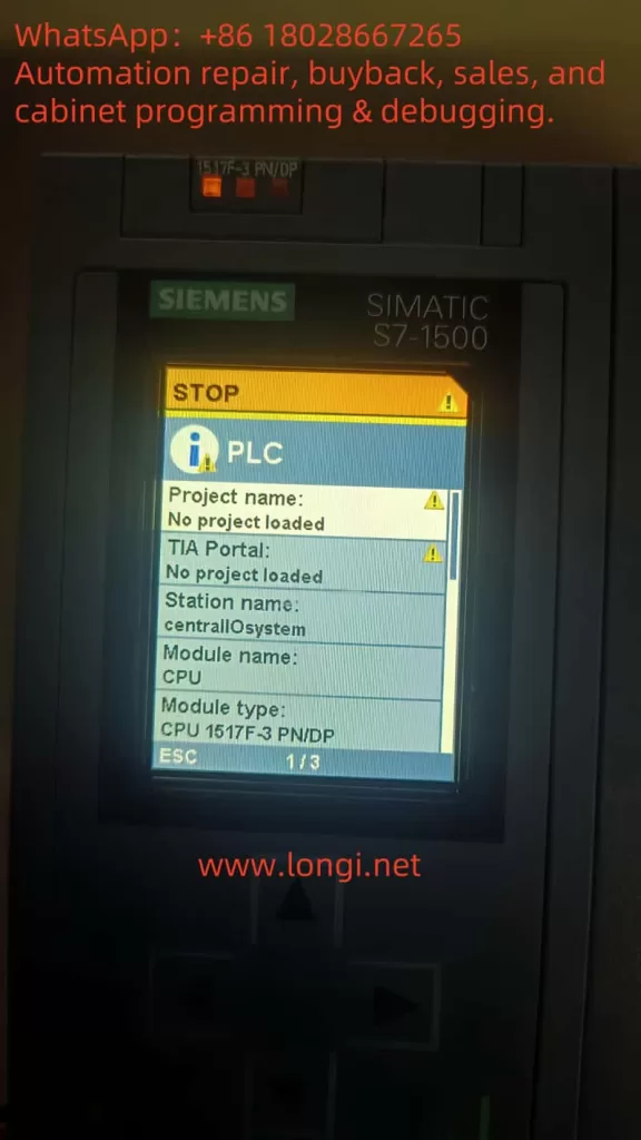
- Check Actual CPU Information: Confirm the CPU’s actual order number and firmware version through its built-in display or TIA’s “Online Diagnostics.” For example, the CPU panel may show the model 1517F-3 PN/DP and firmware version V3.1 (as seen in user-provided photos). Record this information.
- Check CPU Configuration in the Project: Open the “Device Configuration” in the TIA project and verify that the selected CPU model and its firmware version match the actual hardware. Ensure the order number and type are correct. If a different model is used in the project (e.g., 1517-3 instead of 1517F-3, or a different order number suffix), it must be changed. For the firmware version, TIA generally allows selecting different versions supported by the model. Check the CPU properties in the project to confirm the firmware version setting matches or is lower than the actual firmware.
Resolution Steps:
- Update Hardware Support or Upgrade TIA: Ensure TIA Portal has installed the hardware support package (HSP) containing the 1517F-3 PN/DP (6ES7517-3FP01-0AB0). Visit the Siemens official website to download and install the latest HSP for TIA V15. If the HSP is unavailable or the CPU model still does not appear after installation, consider upgrading the software to V15.1 or higher for native support of the new CPU. Newer TIA versions are generally backward compatible with older projects and support newer firmware.
- Modify the CPU in the Project to the Correct Model: In the project tree’s device view, right-click the original CPU module and select “Change Device…”. Locate 1517F-3 PN/DP in the CPU selection list and match the correct order number (note the difference between 3FP00 and 3FP01) and firmware version. For example, select 6ES7517-3FP01-0AB0 with firmware V3.1 (if V3.1 is unavailable in TIA V15, select the highest V2.X version). When changing the device, check “Retain Program” and hardware configuration to avoid losing written logic. After confirmation, the project’s CPU will update to the new model.
- Ensure Project Firmware Version Compatibility: For firmware version mismatches, follow the principle that the project’s firmware version ≤ actual firmware version for normal downloads. For example, a project configured with V2.6 can be downloaded to a CPU with actual firmware V3.1 and run, but new features in V3.1 will not be available. If TIA V15 can only select V2.6 and the CPU is V3.1, this is acceptable. However, if the project’s firmware version is higher than the actual version, lower the project’s version or update the PLC firmware.
- Install the STEP 7 Safety Option (if applicable): Confirm that TIA has the corresponding version of the Safety module installed and a valid safety programming license. If the initial project used a non-Failsafe CPU due to the lack of Safety support, install Safety support first, then replace the CPU with an F-series model and recompile the project. Failsafe PLCs can only download full-featured projects when configured as safety CPUs in the project.
- Attempt Download Again: After making the above changes, recompile the project hardware and try “Download to Device > All.” TIA should now recognize the compatible CPU and no longer report device incompatibility errors. If the error persists, carefully check for differences in the order number/model or consider upgrading TIA.
Note: If upgrading TIA is not possible due to objective constraints, consider downgrading the PLC firmware to a version supported by TIA (not recommended for beginners). For example, some cases involve downloading the program using a higher TIA version, downgrading the CPU hardware information, and then downloading with an older TIA version to enable connection. However, this process is complex and risky; upgrading the software to match the hardware is generally preferred.
Additionally, as a high-end model, the 1517F-3 PN/DP requires a Simatic Memory Card as load memory to run programs (S7-1500 series CPUs must have a card inserted to run; without a card, the CPU cannot enter RUN mode). Therefore, ensure that a non-write-protected SIMATIC memory card is inserted into the PLC during downloads (see the memory card section below for details). Otherwise, downloads may fail or report errors.
2. Troubleshooting and Resolving PLC Model or Project Configuration Mismatches
Cause Analysis: The hardware configuration in the project must exactly match the actual PLC type; otherwise, connection and download attempts will be rejected. For example, in this case, the CPU is a Failsafe model, but if a standard CPU is mistakenly used in the project, TIA will detect the hardware mismatch and report an “incompatible” error. Similarly, if the project’s firmware version is higher than the PLC’s actual version, download attempts will also fail (usually with a version error message). Additionally, if a project previously downloaded by a higher TIA version remains on the CPU, downloading a lower-version project with an older TIA version may cause conflicts, preventing the PLC from recognizing the new project or reporting version inconsistencies. In such cases, the PLC may not recognize the new project or report errors.
Inspection Steps:
- Open the project’s device configuration and verify that the station name, CPU model, and interface configuration match the physical device. Focus on checking whether the correct 1517F-3 PN/DP model is selected (not another model), whether the interface (X2) IP setting is 192.168.1.1, and whether the subnet mask matches the actual network.
- Check the CPU properties for the firmware version setting (if selectable). Ensure it is not higher than the actual PLC firmware. If the project’s firmware version is lower, it is generally acceptable, but you can adjust it to match the actual version as needed to eliminate warnings. Right-click the CPU in the project device and select “Properties” to view the currently configured version and order number, which can be compared with the actual PLC information.
- If a previous download attempt was unsuccessful, residual project data may remain on the PLC’s memory card, causing conflicts during subsequent downloads. Check the CPU display or online diagnostics for information on residual projects or error states (e.g., Memory card LED or maintenance light).
Resolution Steps:
- Correct the CPU Model and Order Number: If the project’s CPU model is incorrect (e.g., 1517 instead of 1517F), follow the previous steps to change it to the correct 1517F-3 PN/DP model. Ensure the order number suffix matches the device (e.g., FP01 vs. FP00). After making changes, regenerate the hardware and software compilation.
- Adjust the Firmware Version Configuration: In the project, set the CPU firmware version to no higher than the actual version. TIA allows switching firmware versions within a certain range (right-click the CPU > Change Version, if available). For example, if the actual PLC is V3.1 and TIA V15 supports up to V2.6, set the project’s CPU version to V2.6. The program can still run, but new features in V3.1 will not be available. If TIA has installed an HSP supporting V3.x, select V3.1 to match exactly.
- Ensure Consistent Project and Station Names (generally does not affect downloads, but recommended for consistency): Ensure that the project’s PLC station name does not conflict with the PLC’s default name, or set a unique name for the CPU as needed and select the appropriate option during download (overwrite the device’s name or retain the device’s name).
- Clear Old Project Data from the PLC: If previous download attempts have left newer version projects or incomplete data on the memory card, clear it first. Method: Format the memory card via the CPU panel or, with the CPU in STOP mode, select “Format Memory Card” in TIA’s “Online & Diagnostics > Functions” to clear the card’s project data. Do not format the SIMATIC card using Windows; only delete project files within it, as formatting with Windows will render the card unusable. Alternatively, remove the memory card, use a PC card reader to delete project files in the SIMATIC.S7S directory (to clear old projects), then reinsert the card and reset the CPU power to prepare it for a clean download.
- Redownload the Project: After ensuring the project configuration matches the hardware and the PLC’s memory card is clean, try downloading again. In TIA, select “Download to Device (Software + Hardware)” and check “Selected Stations” for the current project’s CPU. TIA should now detect the correct device type. If a confirmation dialog appears (e.g., “No project information on the device, load as new station?”), select Load as New Station. During the download, if version warnings appear, follow the prompts and select “Continue” (if it is a firmware upgrade prompt, generally select “No” to retain the current firmware). After completion, a successful download message should appear.
- Check the Running State: After downloading, observe whether the PLC enters RUN mode. If it remains in STOP and displays an “incompatible” message, there may still be configuration mismatches. Use TIA’s “Online > Accessible Devices” to scan and see if the CPU is correctly identified with its firmware. If the device is marked red and labeled “incompatible” in the scan results, the project configuration still does not match the device, requiring you to recheck the above steps.
Note: When a project downloaded by a higher TIA version exists on the PLC, it may leave version information on the memory card, preventing a lower TIA version from directly overwriting it. This is why downloading a V16 project and then attempting to download with V15 fails. Clearing the memory card or formatting it resolves this issue. Therefore, in environments with multiple TIA versions, it is crucial to keep the TIA version consistent with or higher than the project version on the PLC. If you must downgrade the project version, first delete the newer version project data on the PLC before downloading the lower-version project.
3. Troubleshooting and Resolving Network Connection and PG/PC Interface Settings
Cause Analysis: Improper network parameter configuration is a common yet often overlooked cause. Although users can ping the PLC, this does not guarantee proper TIA connection. Common issues include an incorrectly selected PG/PC interface, incorrect IP address/subnet mask settings, conflicts from multiple network cards, or interference from switches or network devices. The ping command typically uses the operating system’s routing to automatically select the network interface, while TIA communication requires sending proprietary protocols through its configured PG interface. Therefore, selecting the wrong interface can result in a situation where the device can be pinged but not found in TIA. Additionally, if the PC and PLC are not in the same subnet or the gateway is unreachable, the device cannot be discovered.
Inspection Steps:
- IP Address and Physical Connection: Confirm that the PC’s IP settings are in the 192.168.1.x subnet (not 192.168.1.1 to avoid conflicts with the PLC) with a subnet mask of 255.255.255.0. Ensure that the Link light on the PC’s network port connected to the PLC is solidly lit. The Profinet green light (Link) on the PLC’s X2 interface should also be lit, indicating a physical connection. If a switch is used, check its indicator lights for normal operation. For testing, connect the PC directly to the PLC to rule out issues with intermediate devices.
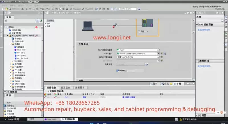
- PG/PC Interface Settings: In TIA Portal, open “Set PG/PC Interface” or click the PG/PC interface icon at the bottom of the software to view the selected interface. Choose the actual network card’s TCP/IP interface used (e.g., “PN/IE -> Intel(R) Ethernet … (192.168.1.x)”). Do not select virtual network cards such as those for PLC simulation or VMware if they are not in use. If multiple interfaces are present, try disabling unused network adapters to ensure TIA binds to the correct card.
- Accessible Devices Scan: In TIA, select “Online > Accessible Devices”, choose the corresponding network card interface, and click “Update”. Check if the PLC and its IP are listed. Ideally, it should display information such as “CPU 1517F-3 PN/DP … IP=192.168.1.1 … Firmware V3.1”. If the list is empty or the device is not found, it may be an interface/firewall issue. If the device is found but marked red as incompatible, return to the previous model matching issue.
- Third-Party Network Environment: If non-standard switches/routers are used, confirm they are not blocking Profinet DCP broadcasts. Profinet device discovery relies on the DCP protocol, which may not work if the switch does not support it. For testing, connect the PC directly to the PLC to rule out switch-related issues.
Resolution Steps:
- Configure Correct IP Settings: Set the PC’s network card IPv4 address to the same subnet as the PLC (e.g., 192.168.1.100) with a subnet mask of 255.255.255.0. The gateway is not required (or can be set to 192.168.1.1). After setting, ping the PLC IP again to confirm connectivity.
- Set the PG/PC Interface: In TIA, select “Online > Set PG/PC Interface” and choose the “TCP/IP -> Local Network Card Name (PN/IE)” option. Ensure the IP address displayed matches the PC’s recently set address. If unsure, select the interface corresponding to your PC’s IP in the interface options. Apply the settings and restart TIA’s device scanning function. With the correct interface settings, TIA should now detect the PLC as easily as connecting to a regular network device. If the wrong port was previously selected, the device should now be found in the scan.
- Resolve Network Adapter Conflicts: If the PC has multiple networks (e.g., WiFi and wired), disable unused adapters to prevent TIA from confusing routing. This is especially important in VMware or other virtual network environments, where you must specify bridging to the correct physical network card. In virtual machines using TIA, configure the virtual network to bridge the physical network card and select the corresponding virtual network card interface in TIA. Additionally, disable the host firewall if necessary. Ensure that only one active network is used for PLC communication.
- Search Again or Connect by Specifying IP: After adjusting the settings, refresh the “Accessible Devices” list in TIA, which should now display the CPU. If the device is still not automatically detected, try manually specifying the IP address for connection in the TIA download dialog: In the download window, click the dropdown arrow next to “Show all accessible devices” and enter
192.168.1.1in the address bar before pressing Enter. This forces TIA to attempt connecting to the PLC at that IP. In many cases, as long as the network and interface are correct, this step will find the device and allow downloading to proceed. - Check for Special Network Factors: If connectivity issues persist, consider whether other software on the computer is occupying ports or filtering traffic. For example, some VPN clients, firewall policies, or group policies may restrict PN port 102 communication. Use the Windows command
netstat -ano | find "102"to check if the port is in use. If necessary, test connectivity on a different computer to determine if the issue is environment-specific. - Ensure No PLC IP Address Conflicts: Confirm that no other device on the network is using the 192.168.1.1 address. Although pinging is successful, it is possible to ping a different device (this can be ignored for direct connections). If multiple PLCs or HMIs are on the network, ensure they all have unique IP addresses.
Note: Ping connectivity only indicates that the ICMP protocol is working, but TIA downloads use the S7 protocol (TCP port 102, etc.). Therefore, it is essential to correctly configure the PG interface and disable the firewall (see the next section) to complete S7 communication. Additionally, Profinet device discovery uses DCP broadcasts, which will not work across subnets or through routers. For cross-subnet downloads, UDP forwarding or direct IP specification methods are required on the router. In most cases, placing the PC and PLC on the same subnet resolves these issues.
4. Troubleshooting and Resolving Firewall and Security Software Issues
Cause Analysis: The Windows firewall and third-party security software may block communication ports required by TIA to access the PLC. A typical manifestation is successful pinging but failure to detect or download from TIA. When the firewall is enabled and does not allow Siemens-related ports, local network connections may be blocked. TIA Portal primarily requires TCP port 102, UDP port 48879, and the DCP protocol for device discovery. If the firewall blocks these, TIA will report connection timeouts or fail to detect devices. Additionally, some domestic antivirus software (e.g., 360 Security Guard, QQ PC Manager) may disable Siemens background services/processes (such as PNIOMGR, S7DOS Service) to optimize the system, causing communication failures. Therefore, both firewall and antivirus software impacts must be considered.
Inspection Steps:
- Firewall Status: Open “Windows Defender Firewall & Network Protection” and check if the firewall is enabled for the current network (domain, private, or public), especially in domain environments where policies may be strict. Try temporarily disabling the relevant firewall and then search for devices in TIA to see if the PLC can be detected. If connectivity is restored immediately after disabling the firewall, the firewall is likely blocking communication.
- Security Software Impact: Check if third-party antivirus or optimization software is installed on the system. These programs may prevent certain services from starting. Open Task Manager or the Services list and look for services with “Siemens” or “S7” in their names, such as “SIMATIC IEPG Help Service” or “SIMATIC S7DOS Service”, and ensure they are running. If any are not running, try starting them manually. Then, check if the security software’s “startup optimization” feature has disabled the PNIOMGR.exe process. This process is crucial for Profinet device management; if disabled, the PLC cannot be detected. If blocked, add it to the security software’s trust list or restore its startup.
- Port Testing: Use Windows PowerShell’s
Test-NetConnection -ComputerName <PLC_IP> -Port 102command to test port connectivity, or use third-party tools (e.g., TCPing) to test whether the PLC’s TCP port 102 is reachable. If the port is unreachable despite successful pinging, the firewall is likely blocking it.
Resolution Steps:
- Disable the Firewall for Testing: To quickly verify, temporarily disable the Windows firewall (for both private and public networks) in the Control Panel’s Windows Defender Firewall settings. Then, retry connecting with TIA. If connectivity is restored, add exception rules for Siemens applications in the firewall instead of leaving it disabled. Open the firewall’s “Allowed apps” settings and ensure TIA Portal and related rules (e.g., “SIMATIC Manager”) are checked, allowing access to required ports (TCP 102, UDP 48879, etc.). For Profinet Discovery, you can also allow the “Profinet Discovery” protocol in the firewall’s advanced settings. After adding rules, re-enable the firewall and observe if connectivity is maintained.
- Adjust or Uninstall Security Software: If using 360 Security Guard, Huorong, QQ PC Manager, or similar software, try temporarily exiting or uninstalling them and then test connectivity. Many cases show that third-party security software secretly blocks industrial communication. If confirmed as the cause, add TIA Portal to the software’s trust list or disable its network protection module. In 360’s “Optimization Accelerator,” restore any disabled Siemens-related services/processes (e.g., if PNIOMGR is disabled, re-enable it in the startup items and restart the computer). Ensure the PNIOMGR process is running (located in C:\Program Files\Common Files\Siemens\Automation\Simatic OAM\bin by default; can be started manually).
- Check System Policies: On some company computers, group policies may disable RPC services or apply AppLocker rules that block TIA components. These can also affect communication. Try installing TIA on a clean personal computer and connecting it directly to the PLC for testing to determine if the issue is environment-specific. If connectivity is restored on a different PC, work with the IT department to restore default firewall rules or disable unnecessary security policies on the original PC.
- Network Isolation Devices: If firewalls or routers are present between the PC and PLC, configure them to allow relevant traffic (e.g., hardware firewalls must allow UDP 67, 68 for DCP and TCP 102). If unsure, the simplest method is to connect directly or use a simple switch for direct connection to avoid interference from network