
I. Operation Panel Functions and Parameter Management
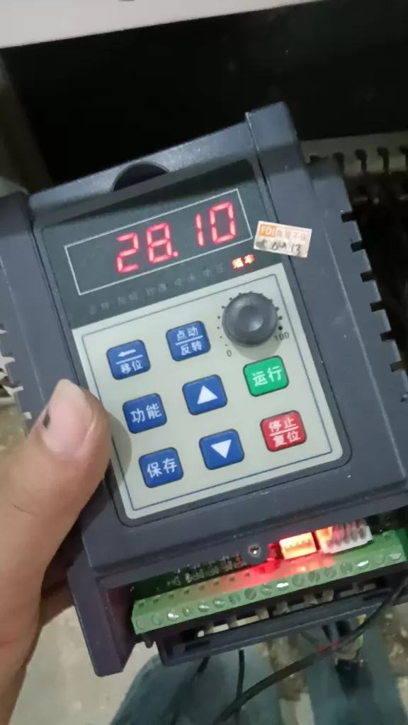
1. Operation Panel Function Introduction
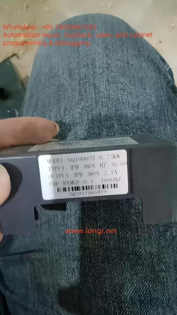
- Applicable Model: SQ-K01 Operation Panel (Refer to pages 8, 18-23 of the manual)
- Core Functional Modules:
- Key Functions:
- Run/Stop: Controls the start/stop of the inverter. Press and hold the “Stop/Reset” key for free stop.
- Function Key: Toggles between monitoring states and menu levels (Primary Menu → Secondary Menu → Parameter Editing).
- Save/Confirm Key: Saves parameter modifications and jumps to the next parameter.
- Shift Key (<<): Switches between monitoring parameters or moves the data editing position.
- Increment (▲)/Decrement (▼) Keys: Adjusts parameter values or function code numbers.
- Indicator Lights:
- FWD/REV: Indicates forward/reverse operation status.
- H/V/A/r/min: Correspond to display units for frequency, voltage, current, and speed, respectively.
- Digital Display: 5-digit LED displays parameter values, fault codes, or operational data (e.g., output frequency 50.00Hz).
- Key Functions:
2. Parameter Initialization
- Steps (Refer to parameter F2.00 on page 29 of the manual):
- Enter the primary menu and select
-F2-(Auxiliary Settings Group). - Enter the secondary menu and select
F2.00(Parameter Initialization). - Set to
1to restore factory settings, or2to clear fault records. - Press the “Save” key to confirm, and the inverter will restart automatically to take effect.
- Enter the primary menu and select
3. Password Setting and Removal
- Setting Password (Parameter F2.03 on page 29 of the manual):
- Enter
F2.03(Parameter Permission Modification Password) and input a value between 0-65535. - After saving, entering this password will be required to modify other parameters.
- Enter
- Removing Password: Reset
F2.03to0to cancel password protection.
4. Parameter Access Restrictions
- Setting Method: Set permissions via
F2.01(Parameter Write Protection) (Refer to page 29 of the manual) - Permission Options:
- 0: Allows modification of all parameters (some parameters cannot be modified during operation).
- 1: Only allows modification of the digital set frequency (F0.02).
- 2: Prohibits modification of all parameters (only F2.01 and F2.03 can be adjusted).
II. External Terminal Control and Potentiometer Speed Regulation Settings
1. External Terminal Forward/Reverse Control
- Wiring and Parameter Settings (Refer to pages 12-15, 46-48 of the manual):
- Wiring Terminals:
- Power Input: L/N (Single-phase 220V) or R/S/T (Three-phase 380V).
- Control Terminals: X1-X6 are multi-function inputs, COM is the common terminal.
- Example Wiring: X1 connected to the forward rotation button, X2 connected to the reverse rotation button, both short-circuited with COM to take effect.
- Parameter Settings:
- F0.00: Set to
1(External Terminal Control Mode). - F4.00-F4.05: Define terminal functions (e.g., X1=5 “Forward Rotation”, X2=6 “Reverse Rotation”).
- F4.06: Select control mode (recommended
2Two-Wire Control Mode 1, FWD/REV independently controlled).
- F0.00: Set to
- Wiring Terminals:
2. External Potentiometer Frequency Speed Regulation
- Wiring and Parameter Settings (Refer to pages 14-15, 36-37, 51 of the manual):
- Wiring Terminals:
- Analog Input: AII (0-10V) connected to the middle pin of the potentiometer, COM connected to the negative terminal, 10V terminal connected to the power positive terminal.
- Jumper Setting: The J1 jumper on the control board needs to be short-circuited to the “V” side (voltage input mode).
- Parameter Settings:
- F0.01: Set to
3(External Analog Signal AII for Frequency Setting). - F5.00-F5.03: Calibrate the input range (default 0-10V corresponds to 0-100% frequency).
- F5.04: Adjust the filtering time (default 0.2 seconds, for anti-interference purposes).
- F0.01: Set to
- Wiring Terminals:
III. Fault Code Analysis and Handling Methods
Common Fault Codes and Solutions (Refer to pages 65-66 of the manual)
| Fault Code | Meaning | Solution |
|---|---|---|
| E001 | Acceleration Overcurrent | Check motor load, extend acceleration time (F0.06). |
| E004 | Acceleration Overvoltage | Increase deceleration time (F0.07), check braking resistor. |
| E009 | Radiator Overheating | Clean the air duct, ensure ambient temperature ≤40℃. |
| E010 | Inverter Overload | Reduce load or increase inverter capacity. |
| E011 | Motor Overload | Adjust F8.01 (Motor Overload Protection Coefficient). |
| E015 | Undervoltage During Operation | Check input power voltage, adjust F8.06 threshold. |
| E016 | EEPROM Read/Write Fault | Restore factory parameters, contact the manufacturer to replace the storage chip. |
General Fault Troubleshooting Steps:
- Power-Off Inspection: Disconnect the power supply for 5 minutes, check for loose or short-circuited wiring.
- Reset Operation: Press the “Stop/Reset” key to clear the fault and power on again.
- Parameter Verification: Confirm that key parameters (such as F0.03 maximum frequency, F3 group motor parameters) match the equipment.
- Contact Support: If the fault persists, record the code and contact the manufacturer (Phone: 17328677949).
IV. Conclusion
The SQ1000 inverter meets complex industrial demands through flexible parameter configuration and diverse control methods. Users must strictly adhere to the safety specifications in the manual (such as grounding and heat dissipation requirements) and perform regular maintenance to extend the equipment’s lifespan. Mastering the operation panel functions, external control settings, and fault handling techniques can significantly improve equipment operational efficiency and stability. It is recommended to keep the manual and refer to it regularly to ensure compliance and safety in operations.