
Abstract
This article systematically examines a field case involving the co-occurrence of F30022 (Power Unit U_ce Monitoring Fault) and A7852 (External Alarm 3) in a G120L inverter used in a 315 kW water pump application. It delves into the fault mechanisms, provides a detailed eight-step troubleshooting process, outlines testing methods and replacement techniques for commonly damaged components, and summarizes five preventive maintenance points based on maintenance statistics.
I. Fault Phenomena and Code Interpretation
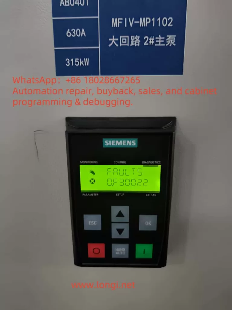
Fault Code F30022: Power Module U_ce Monitoring Triggered
Definition: The power unit continuously monitors the collector-emitter voltage (U_ce) during IGBT conduction. If an abnormal voltage waveform is detected, a hard fault is triggered, and the pulses are locked out.
Common Causes:
- Output phase-to-phase or phase-to-ground short circuits or motor winding breakdown.
- IGBT module internal breakdown (due to overheating, aging, or surge impacts).
- Loss of 24 V power supply to the gate drive or blown fuses on the circuit board.
- Interruption of the fiber-optic link between the Control Unit (CU) and Power Module (PM), leading to sampling loss.
- Improper system grounding, causing harmonic currents to return through the PE line and elevate the sampling ground potential.
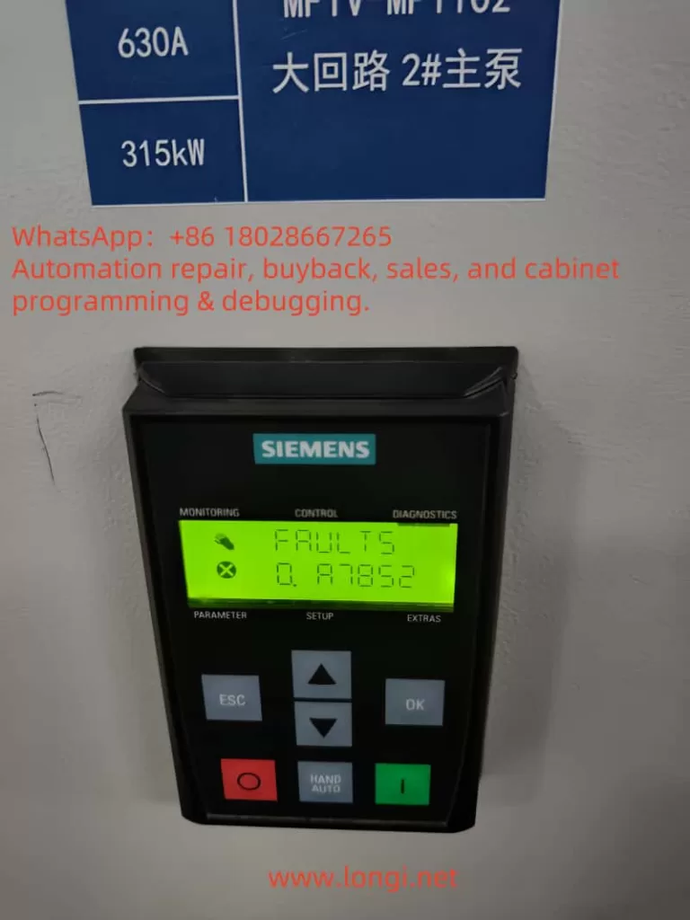
Alarm Code A7852: External Alarm 3
Definition: A digital input is mapped via parameter p2117. When its status meets the trigger condition, the alarm is set. This does not shut down the power but only indicates an external interlock anomaly.
Typical Trigger Sources:
- Closure of fire/emergency stop circuits.
- Faults in cooling water pressure, oil station pressure, or PLC outputs.
- Loose terminals or poor shielding grounding leading to interference pulses.
When F30022 and A7852 occur simultaneously, it often indicates hardware defects in the power stage and an alarm state in the field interlock, requiring separate handling.
II. Eight-Step Systematic Troubleshooting Process
| Step | Operation Points | Purpose and Acceptance Criteria |
|---|---|---|
| 1 | Power-off insulation test: Measure U/V/W→PE with a 500 V megohmmeter (≥ 5 MΩ) | Determine if motor/cable insulation is degraded |
| 2 | Phase-to-phase short circuit test: Remove motor terminals and measure U-V/V-W/U-W resistance (should equal rated value) | 0 Ω indicates winding short circuit |
| 3 | IGBT diode measurement: Use a multimeter’s diode mode to measure forward and reverse | Bidirectional 0 Ω indicates module breakdown |
| 4 | Drive board 24 V verification: Check 24 V and 15 V supplies on the gate drive board | Lack of power supply may falsely trigger F30022 |
| 5 | Fiber-optic link self-test: Check Rx/Tx indicators on CU and PM ends (should be constantly lit) | Dim or flickering lights indicate link interruption |
| 6 | Resolve A7852: View p2117 corresponding DI, short-circuit/disconnect to verify | Confirm the true source of the external alarm |
| 7 | No-load test run: Remove U/V/W and power up | If F30022 does not reoccur, the problem is on the motor side |
| 8 | Load retest: After replacing/repairing components, reconnect the motor for test run | r0947 shows no faults, and operation is stable |
III. Practical Maintenance Case
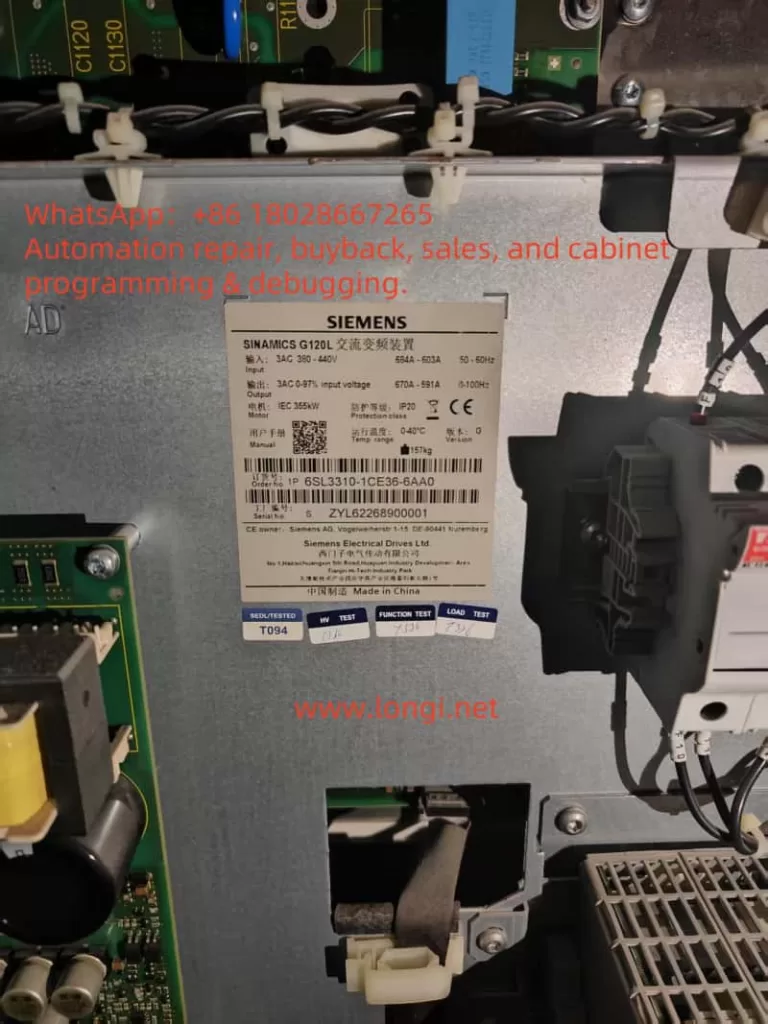
Device Overview: G120L-315 kW + CU240E-2PN control unit driving a circulating water pump. First occurrence of F30022 + A7852 after 5 years of operation.
Initial On-site Screening: Megohmmeter reading of only 0.2 MΩ indicates insulation breakdown. Line-to-line resistance measurement of U-V at 0.3 Ω (should be 0.75 Ω) confirms motor short circuit.
Power Module Inspection: U-arm IGBT measures bidirectional 0 Ω, indicating hard breakdown. The same-side drive board’s 24 V fuse is blown.
Component Replacement: Replace 2×1700 C-rated IGBTs, rewire, replace the fuse, and clean the cooling channel.
Fiber-optic Reset: Re-plug the CU-PM POF; indicators return to a constantly lit state.
External Alarm Handling: p2117=1101, corresponding to DI4. Found that the fire interlock test line was not reset → restored, and A7852 disappeared.
Test Run and Delivery: First, a no-load test run, followed by a 50 Hz full-load test run for 1 hour. No alarms occurred; delivered to production.
IV. Component Prices and Typical Labor Hours Reference
| Item | Price (CNY) | Labor Hours (h) | Notes |
|---|---|---|---|
| 1700 C IGBT module ×2 | 11,800 ×2 | — | Original parts |
| POF fiber-optic docking kit | 260 | — | 2 m |
| 24 V fuse + terminals | 120 | — | — |
| Maintenance labor | — | 16 ×350 = 5,600 | Includes disassembly, testing, debugging |
| Insulating materials/thermal maintenance | 500 | — | Cleaning + painting |
| Total | ≈30,000 | 16 | Completed within two working days |
V. Five Key Points for Preventive Maintenance
- Online Insulation Monitoring: Install an IDAX-M to issue an early warning when insulation drops below 2 MΩ.
- Quarterly Thermal Cleaning: Use compressed air to blow out air ducts and check r0035 temperature rise. Immediately address any rise >10 K.
- Standardized Power-Up Sequence: Turn on the main circuit first, followed by the 24 V control power supply to avoid false alarms due to premature power-up of the drive board.
- Layered External Alarms: Digest external alarm signals within the PLC and connect only the total OK contact to the drive to reduce false stops.
- Surge and Harmonic Suppression: Install a 690 VAC SPD + 3% reactor at the incoming line to reduce dv/dt impacts on the IGBTs.
VI. Conclusion
F30022 represents a “red alert” at the power stage level, while A7852 serves as a “yellow light” at the system level. When both codes occur simultaneously, it is essential to investigate both hardware and external interlocks. Through structured eight-step troubleshooting, rigorous component testing, replacement, and debugging, production can be restored for a 315 kW water pump within 48 hours. By implementing preventive measures such as insulation monitoring, thermal cleaning, grounding optimization, and surge/harmonic suppression, the risk of similar shutdowns can be significantly reduced. It is hoped that the cases and methodologies presented in this article will provide practical assistance to on-site maintenance engineers and serve as a reference for equipment managers in formulating preventive maintenance plans.