
1. Overview
Ceramic rolling forming equipment is a typical multi-axis automatic machine widely used in the initial pressing of electronic, structural, and functional ceramics. The system usually consists of a servo control unit, electrical control system, pneumatic components, and a rolling head. This document introduces in detail how to apply the LTI Motion ServoC series servo drive in combination with the Mitsubishi FX3U series PLC, covering the application strategy, wiring diagram, parameter configuration, and control logic.
2. Application Scenario and System Structure
This system involves two servo control units:
- Pressing Axis Servo: Drives the pressing roller vertically to compress ceramic blanks.
- Rotary Table Servo: Controls intermittent indexing of the rotary table for sequential forming.
3. Key Functional Requirements
- Precise positioning of the pressing head for consistent product thickness.
- Indexing rotation of the rotary table with accurate angular control.
- Multi-sensor interlock with limit switches and origin sensors.
- Safety integration with emergency stops, alarms, and feedback loops.
4. Hardware and Wiring Configuration
- PLC: Mitsubishi FX3U-48MR/ES-A
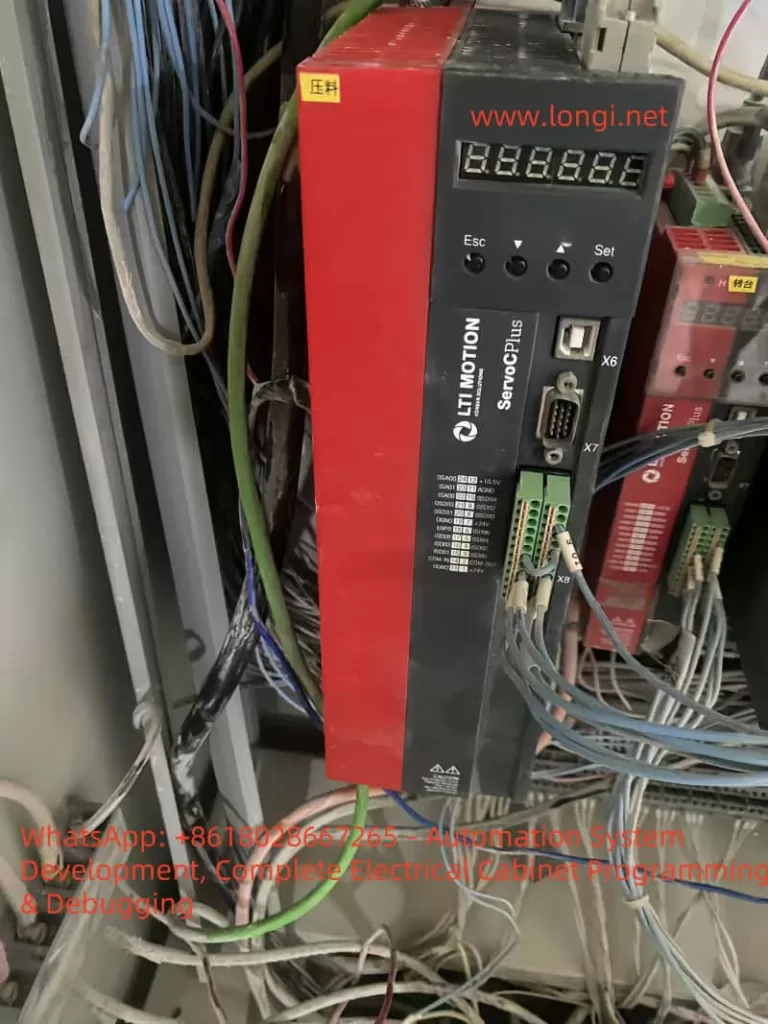
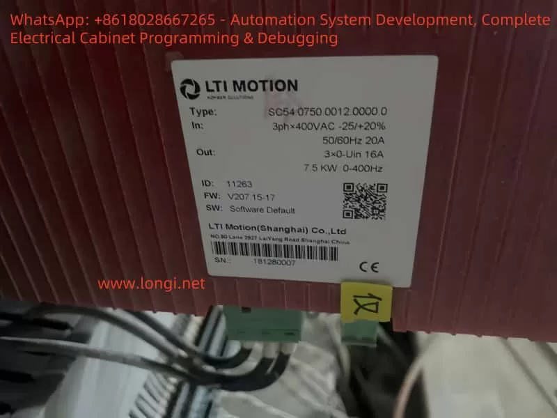
- Servo Drive: ServoC SGS4.0750.0012.0000.0 (LTI Motion)
- Motor: Matching LTI servo motor (1.5~2.2kW)
- Power Supply: 3-phase 400VAC
5. Detailed Servo Wiring
5.1 Pressing Servo (I/O Mode Control)
| ServoC Terminal | Function | Connect to PLC |
|---|---|---|
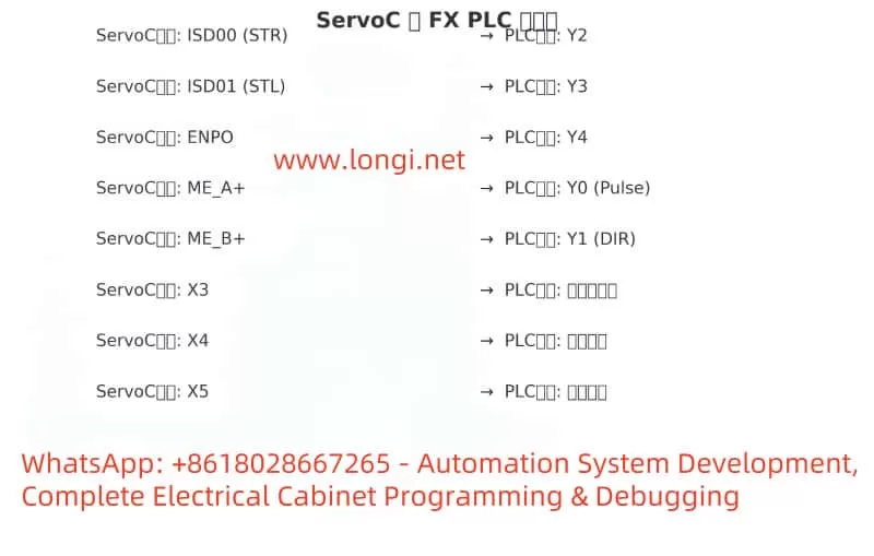
| ISD00 | STR (Forward) | Y2 |
| ISD01 | STL (Reverse) | Y3 |
| ENPO | Enable | Y4 |
| DGND | Ground | 0V |
5.2 Rotary Table Servo (Pulse + Direction Mode)
| ServoC Terminal | Function | Connect to PLC |
|---|---|---|
| ME_A+ | Pulse+ | Y0 |
| ME_B+ | Direction+ | Y1 |
| ENPO | Enable | Y4 |
5.3 Sensor Inputs
| Sensor | Description | Connect to PLC |
|---|---|---|
| Origin Sensor | Pressing Axis Home | X3 |
| Bottom Sensor | Pressed Position | X4 |
| Table Sensor | Index Complete | X5 |
6. ServoC Parameter Configuration
- P145 = 4: Position control mode
- P152 = 1 or 2: Set input mode to pulse+direction or I/O trigger
- P210 = 2; P211 = 3: Set ISD00 to STR, ISD01 to STL
- P483 = 2 or 3: Motor direction configuration
- P759 / P760: Software limit for press upper/lower bounds
- P803: Position error tolerance
7. Control Logic Sequence
- Power ON → Y4 output to enable servos.
- Origin detection via X3 → Set M10 (homed flag).
- Start pressing:
- X0 input triggers Y2 = ON (STR), Y3 = OFF (STL).
- X4 bottom sensor triggers M20.
- Return press head:
- X1 input triggers Y3 = ON (STL), Y2 = OFF.
- Rotate table:
- X2 input + M20 triggers 2000 pulses via Y0 and DIR = Y1.
- X5 confirms rotation complete (M31).
8. Ladder Diagram (Simplified)
LD M8013
OUT Y4 ; Servo Enable

LD X3
OUT M10 ; Homed flag

LD X0 AND M10
OUT Y2
RST Y3

LD X1 AND M10
OUT Y3
RST Y2

LD X4
OUT M20

LD X2 AND M20
RST M20
SET Y1
PLS Y0 K2000

LD X5
OUT M31
RST M30
9. Diagrams and Application Notes
10. Conclusion and Recommendations
This solution demonstrates the application of ServoC servo drives in high-precision ceramic roller forming machines using Mitsubishi FX3U PLCs.
Best Practices:
- Set software travel limits.
- Implement emergency stops and feedback alarms.
- Always home the servo before operation.
- Use opto-isolated I/O to reduce interference.
Future Extensions:
- Integrate HMI for parameter recipes and alarms.
- Add pressure sensors and linear encoders for quality control.
- Expand to multi-station synchronization with communication protocols.