
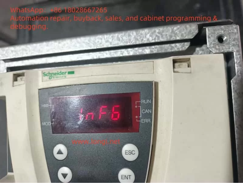
Meaning of the INF6 Fault Code
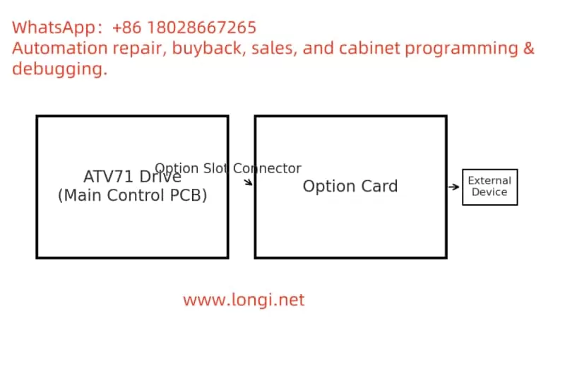
The INF6 fault in Schneider Electric’s ATV71 variable frequency drive (VFD) indicates an internal option card fault, specifically that the drive fails to detect or recognize an installed option card. This card could be a communication module, encoder feedback interface, or an I/O extension board, all of which are connected via internal slots to the main control board.
In crane applications, option cards are frequently used for advanced functions such as closed-loop vector control via encoder feedback or communication with PLCs or remote systems through fieldbus networks like Profibus, CANopen, or Modbus.
Typical Scenarios Leading to INF6 in Crane Environments
- Card Loose or Poor Contact Due to Vibration
Cranes often cause mechanical vibration and shock, especially during lifting or brake engagement. These vibrations can loosen option cards that are not well-secured, leading to intermittent or complete disconnection from the control board. - Incompatibility or Conflict Between Cards
Installing incompatible option cards or using two mutually exclusive modules can lead to detection failures. For instance, some ATV71 models do not support simultaneous installation of multiple communication cards. - EMI (Electromagnetic Interference)
High-voltage motors, contactors, and solenoids in cranes generate strong electrical noise. If signal lines or the power supply to the card are interfered with, the card may fail during boot-up, leading to INF6. - Hot-Swapping or Improper Handling
Inserting or removing cards while the drive is powered can instantly damage internal circuits or corrupt detection logic. - Card Failure or Aging
Cards may fail due to temperature stress, component aging, or EEPROM corruption, particularly in harsh crane environments.
On-site Troubleshooting Process and Required Instruments
1. Safety Shutdown and Visual Inspection
- Disconnect all power and wait for DC bus discharge.
- Remove the front cover of the VFD and inspect the option card seating.
- Re-insert and firmly fix the card to ensure solid contact.
2. Socket and PCB Inspection
- Examine socket pins for oxidation, damage, or bent pins.
- Use a flashlight and multimeter (in continuity mode) to check connection integrity between slot pins and main board.
- Clean contacts with alcohol if dirt or corrosion is found.
3. Substitution Testing
- Insert a known-good card to see if the error clears.
- Try the faulty card in a different VFD. If the error moves with the card, the card is faulty. If not, suspect the VFD mainboard.
4. Firmware and Parameter Checking
- Connect a PC via Schneider’s SoMove software and read diagnostic registers.
- Check if the card appears in the identification menu. If not, it’s either faulty or incompatible.
- Confirm compatibility of the card model with current firmware version.
5. Instrumental Diagnosis
- Multimeter: Measure slot power pins (usually +5V or +24V).
- Oscilloscope: Check clock/data lines of the card communication interface (e.g., SPI, I²C).
- Thermal Camera: Detect abnormal heat signatures on card or mainboard.
- Bus Analyzer: For communication cards, monitor if signals are transmitted at all.
Maintenance and Repair Strategy
Basic Solutions
- Reseat the card and retest.
- Replace card if visibly damaged or if substitution confirms card failure.
- Remove additional cards if there is a slot conflict.
Power Supply Repair
- If slot voltage is missing or unstable, investigate the power regulator or filtering section of the mainboard.
Cold Solder Joint Repair
- Check socket solder points under magnification. Repair any cracked or cold solder joints using a soldering iron.
Firmware Updates
- If firmware mismatch is suspected, update the drive firmware using official Schneider tools.
Observe Handling Rules
- Always power down before inserting/removing cards.
- Avoid touching card contacts with bare hands.
Advanced PCB-Level Diagnostics (for Experienced Engineers)
If all above steps fail:
- Study Schematics
Locate option slot pin functions and their connections to ICs or CPU. - Signal Tracing
Use an oscilloscope or logic analyzer to trace data lines between the card and CPU. Look for absence or corruption of signals. - Component Testing
- Check if line driver/receiver ICs (e.g., RS-485 transceivers) are working.
- Verify presence of proper clock signals and EEPROM integrity.
- Chip Replacement
- If suspect components (e.g., voltage regulators, buffer ICs) are identified, carefully desolder and replace them.
- Use thermal camera post-repair to confirm heat profile normalization.
Summary
For a field engineer maintaining crane control systems, an INF6 error is not just a code—it’s a call for systematic diagnosis. Whether caused by vibration, poor contact, firmware mismatch, or a damaged card, INF6 can typically be resolved with structured inspection and substitution.
When the root cause lies deeper—within power supplies, communication buses, or chip-level failures—a disciplined approach using schematics, meters, and scopes becomes essential. Through careful inspection, methodical replacement, and sometimes PCB-level repair, an engineer can confidently restore the VFD’s full functionality.
Let this guide serve as your reference for future INF6 cases on Schneider ATV71 drives, ensuring minimal downtime and safe crane operation.