
Introduction
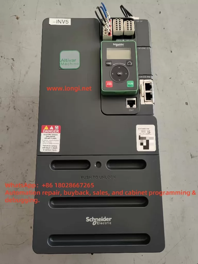
Variable frequency drives (VFDs) are critical components in modern industrial automation systems, widely used in motor control applications to achieve precise speed and torque regulation, enabling efficient production, energy savings, and extended equipment lifespan. Schneider Electric, a globally renowned electrical equipment manufacturer, offers the ATV340 series VFDs, which are known for their superior performance, high reliability, and versatile features. These drives excel in industrial applications requiring high dynamic response and precise control, such as cranes, conveyor systems, and processing machinery.
However, in practical applications, the ATV340 VFD may encounter various faults, one of which is the “Load Movement Error” (fault codes [nLdCF] or [MDCF]). This fault can disrupt production processes, potentially cause equipment damage, or pose safety risks, making timely identification and resolution essential. This document provides a detailed analysis of this fault, covering its definition, causes, diagnostic methods, solutions, and preventive measures to assist users in effectively addressing the issue.
Fault Description
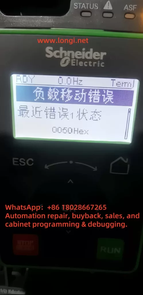
The “Load Movement Error” occurs when the load (i.e., the mechanical component driven by the motor) moves unexpectedly without any motion command. On the ATV340 VFD’s display, this fault is typically indicated as “Load Movement Error” or the code “nLdCF,” and it may also appear as “0050Hex” in hexadecimal format. According to the Schneider ATV340 programming manual, this error indicates that the system has detected abnormal load behavior during a stopped or uncontrolled state.
Fault Symptoms
- Display Indication: The VFD displays “Load Movement Error” or “nLdCF” and enters a fault protection state.
- Motor Behavior: The motor may rotate unexpectedly when not commanded, or the load may shift after the motor stops.
- System Impact: The VFD ceases output, preventing normal motor operation, which may lead to production interruptions.
This fault is particularly critical in applications like cranes or hoists, as unexpected load movement could result in dropped cargo, equipment damage, or safety hazards for on-site personnel.
Fault Cause Analysis
The “Load Movement Error” can stem from various factors. The following are common causes based on the ATV340 programming manual and practical application experience:
1. Brake System Issues
- Brake Command Circuit Problems: Loose wiring, poor contact, or damaged components in the brake command circuit may prevent proper transmission of brake signals, causing the brake to fail.
- Brake Failure: Mechanical wear, improper adjustment, or aging of the brake itself may result in insufficient braking force, failing to prevent load movement.
2. Incorrect Parameter Settings
- Load Movement Detection Parameters: The ATV340 supports load movement detection through parameters [BRH b5] and torque threshold reference [TTR]. If [BRH b5] is not enabled (default is NO) or [TTR] is set inappropriately, it may lead to missed or false detections.
- Mismatched Motor Control Type: If the parameter [CTT] (motor control type) is not set correctly to [FVC] (standard for asynchronous motors) or [FSY] (standard for synchronous motors), it may cause control instability, leading to abnormal load movement.
- Insufficient Load Holding Time: If the parameter [MD FT] (load holding time) is set too short, the system may fail to detect load status properly after power restoration, triggering the error.
3. Mechanical System Issues
- Loose Transmission Components: Loose or damaged couplings, gears, or belts may allow the load to move even when the motor is stopped.
- Unstable Load Fixation: In hoisting applications, an unstable load center of gravity or faulty securing mechanisms may cause movement due to gravity.
4. Electrical System Issues
- Unstable Power Supply: Voltage fluctuations or momentary power interruptions may disrupt the VFD’s normal control, leading to load instability.
- Electromagnetic Interference: Strong electromagnetic interference on-site may affect the VFD’s signal processing, causing erroneous actions.
5. External Factors
- External Forces: Forces such as wind, gravity, or other external influences acting on the load may cause movement when the motor is stopped.
Fault Diagnosis Methods
To accurately identify the cause of the “Load Movement Error,” users can follow these systematic diagnostic steps:
1. Review Fault Information
- Check Display: Note the fault code (e.g., “nLdCF” or “0050Hex”) and the “Latest Error 1 Status” on the VFD display.
- Access Fault History: Use programming software or an HMI to review the fault occurrence time and frequency to analyze triggering conditions.
2. Inspect Brake System
- Brake Command Circuit: Use a multimeter to test the continuity of the circuit wiring and verify the functionality of relays or contactors.
- Brake Condition: Manually check the brake’s engagement and release to ensure its mechanical performance is intact.
3. Verify Parameter Configuration
- Load Movement Detection: Access the parameter menu and confirm if [BRH b5] is set to “YES” (enabled). If set to “NO,” the detection function is disabled.
- Motor Control Type: Ensure the [CTT] parameter matches the motor type ([FVC] for asynchronous motors, [FSY] for synchronous motors).
- Load Holding Time: Check the [MD FT] setting, which defaults to 1 minute. Adjust it to 1–60 minutes based on application needs.
4. Inspect Mechanical System
- Transmission Components: Check for looseness or wear in couplings, gears, or other components.
- Load Fixation: Ensure the load is securely fixed in the stopped state and not subject to external forces.
5. Monitor Electrical Environment
- Power Quality: Use a voltmeter to monitor input voltage, ensuring it remains within the VFD’s acceptable range (typically 380V ±15%).
- Electromagnetic Interference: Assess whether strong interference sources, such as high-power equipment or unshielded cables, are present on-site.
6. Observe Load Behavior
- Under safe conditions, disconnect the motor power and observe whether the load moves due to external forces or mechanical looseness.
Fault Resolution Measures
Based on the identified causes, the following are specific solutions:
1. Repair Brake System
- Circuit Repair: Replace damaged wiring or components to ensure accurate brake command transmission.
- Brake Adjustment: Repair or replace the brake to ensure sufficient braking force and timely response.
2. Optimize Parameter Settings
- Enable Detection Function: Set [BRH b5] to “YES” to activate load movement detection.
- Adjust Torque Threshold: Configure [TTR] based on load characteristics to ensure appropriate detection sensitivity.
- Match Control Type: Set [CTT] to [FVC] or [FSY] to align with the motor type.
- Extend Holding Time: Adjust [MD FT] to an appropriate value (e.g., 5 minutes) to prevent false alarms after power restoration.
3. Strengthen Mechanical System
- Tighten Components: Secure or replace loose transmission components.
- Secure Load: Add fixing mechanisms to ensure load stability.
4. Improve Electrical Environment
- Stabilize Power Supply: Install a voltage regulator or UPS to maintain stable voltage.
- Reduce Interference: Shield control circuits and optimize equipment layout to minimize electromagnetic interference.
5. Clear Fault Code
- Reset Operation: After resolving the issue, use the [ATR] (automatic fault reset) or [RSF] (reset fault) parameter to clear the error code. If necessary, reset [MTBF] (load holding delay) by powering off and restarting the device.
Preventive Measures
To reduce the likelihood of “Load Movement Error,” users can implement the following preventive measures:
1. Regular Maintenance
- Brake System: Inspect the brake and its circuit monthly, replacing worn components promptly.
- Mechanical System: Regularly tighten transmission components to prevent looseness.
2. Standardized Parameter Management
- Parameter Backup: Save parameter configurations after commissioning for quick restoration after faults.
- Periodic Review: Check critical parameters (e.g., [BRH b5], [CTT]) quarterly to ensure correctness.
3. Personnel Training
- Operational Standards: Train operators on proper VFD usage to avoid errors.
- Emergency Handling: Teach basic fault diagnosis skills to improve response capabilities.
4. Optimize Operating Environment
- Power Protection: Ensure a stable power supply to avoid fluctuations.
- Interference Mitigation: Optimize wiring to reduce electromagnetic interference.
Conclusion
The “Load Movement Error” is a common fault in Schneider ATV340 VFDs, potentially caused by brake system failures, incorrect parameter settings, mechanical looseness, electrical issues, or external forces. Through systematic diagnosis—reviewing fault information, inspecting brake and mechanical systems, and adjusting parameters—users can effectively identify and resolve the issue. Additionally, preventive measures such as regular maintenance, standardized operations, and environmental optimization can significantly reduce fault occurrences, ensuring long-term stable equipment operation.
In industrial automation, promptly and accurately addressing VFD faults is critical to maintaining production efficiency and safety. This document aims to provide practical guidance to help users better understand and manage the ATV340’s “Load Movement Error,” enhancing their confidence and capability in equipment management.