
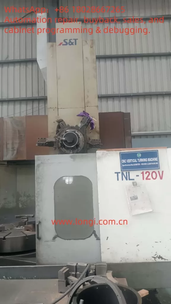
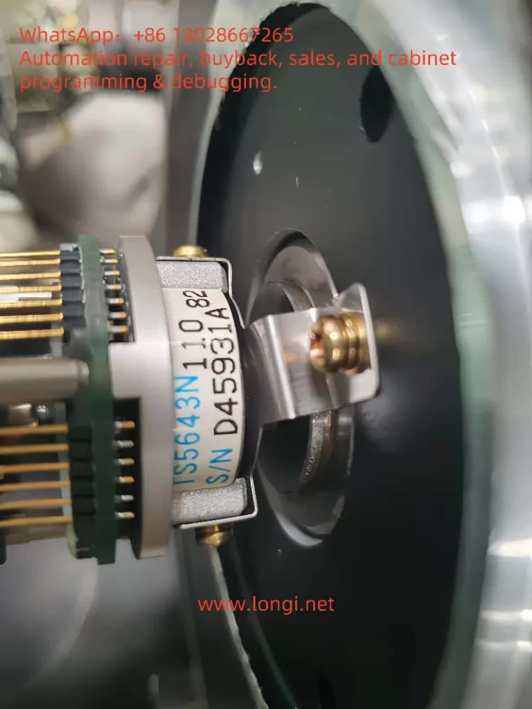
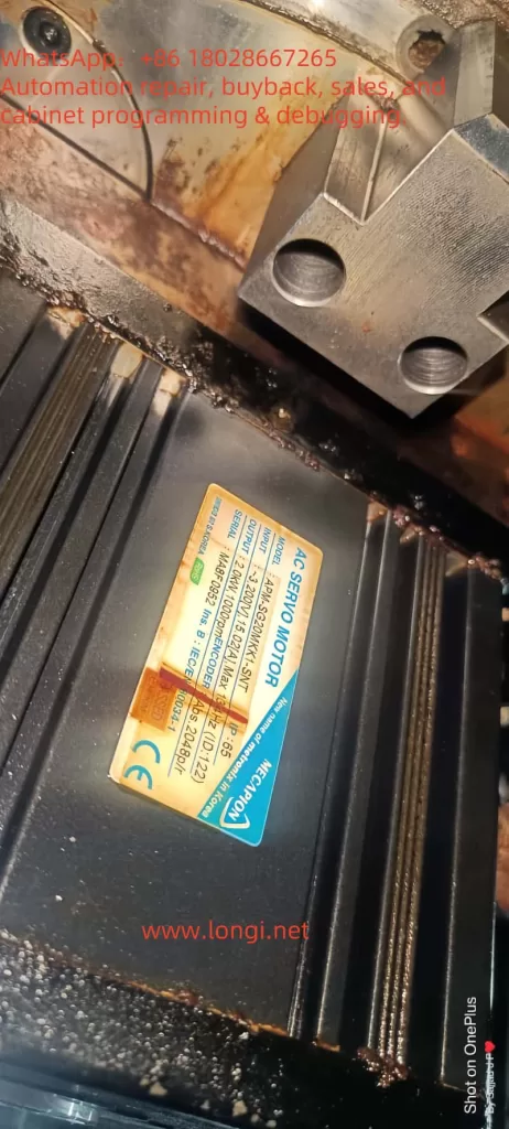
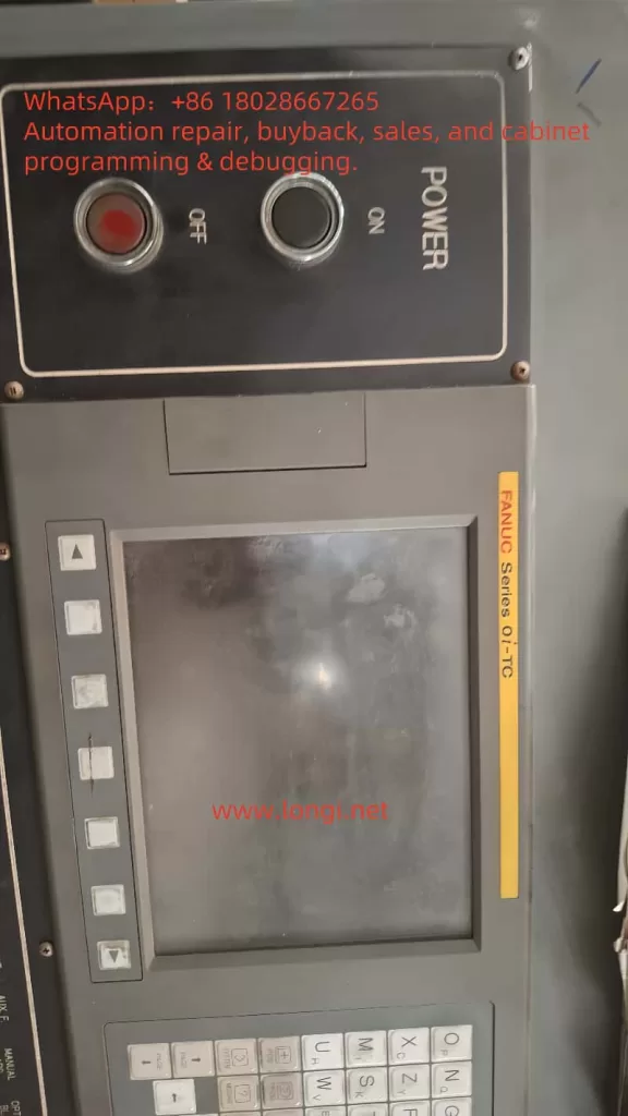
Applies to: Fanuc Series 0i‑TC CNC + S&T TNL‑120V vertical turning lathe. The turret axis uses an LS Mecapion APM‑SG20MKX1‑SNT servo motor driven by an APD‑VP20(SNT) servo amplifier. The motor is equipped with a TS5643N1 multi‑turn absolute encoder (2048 P/R).
Symptom: The internal lithium battery of the LS drive failed → drive raised AL‑14/AL‑15 absolute‑data/battery errors → the customer, suspecting a bad encoder, loosened the flexible coupling between encoder and motor → the encoder zero position no longer matches the motor’s electrical 0° → even after replacing the battery, absolute position is offset and the Fanuc CNC continues to alarm, rendering the machine inoperable.
Contents
- System architecture & fault background
- Relationship between absolute encoders and electrical 0°
- Root‑cause chain analysis
- Tools & safety preparation
- Step‑by‑step restoration workflow
5.1 Replacing the drive battery
5.2 Mechanical realignment of the coupling
5.3 Drive parameter & menu operations
5.4 Rebuilding the reference point inside Fanuc - In‑depth explanations of key menus
6.1PC‑806 Z POS Search
6.2PC‑811 ABS Encoder Set
6.3 HSIN/HSOUT handshake for absolute data - Commissioning and verification
- Preventive measures & maintenance tips
- FAQ
- Closing remarks
1 System Architecture & Fault Background
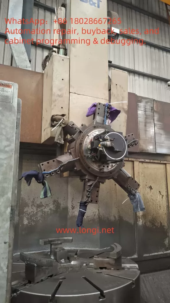
1.1 Machine configuration
- Machine: S&T TNL‑120V vertical turning center with 8‑station turret.
- Control: Fanuc Series 0i‑TC. Spindle and linear axes use standard FANUC α drives. The turret axis, however, is an LS Mecapion solution supplied by the OEM (S&T) for cost optimisation.
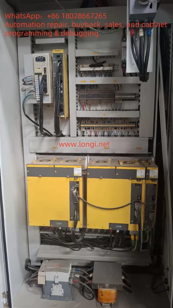
- Turret servo package:
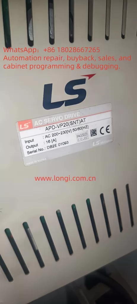
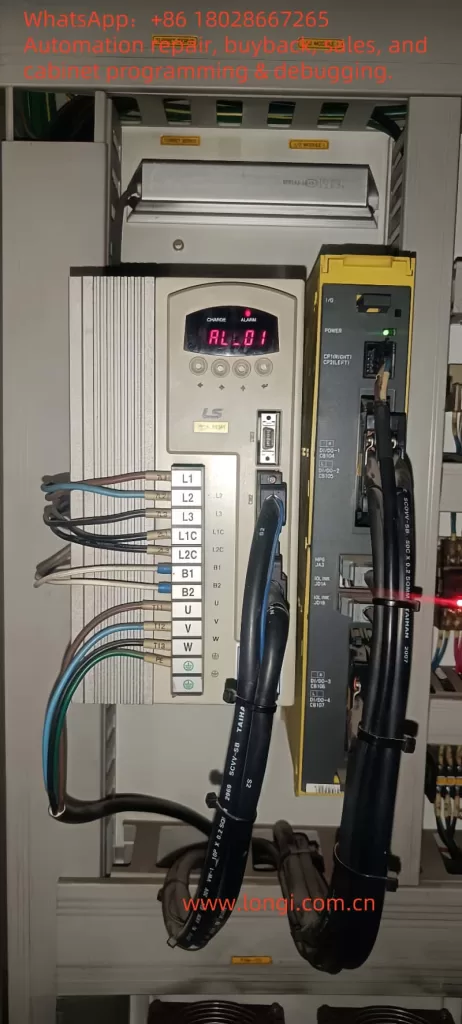
- Drive: APD‑VP20(SNT) AC servo amplifier (200 – 230 VAC, 3‑phase).
- Motor: APM‑SG20MKX1‑SNT, 2 kW @ 1 000 rpm, absolute encoder, IP‑65, with brake.
- Encoder: TS5643N1 multi‑turn absolute optical/magnetic hybrid, ABZ incremental outputs + serial multi‑turn data.
- Signal exchange with Fanuc is via dry‑contact and PMC bits for turret index, clamp/unclamp and axis ready.
1.2 Absolute‑backup battery
The APD‑VP20 houses a 3 V lithium cell (CR‑1/2AA or equivalent) that keeps encoder multi‑turn data and drive parameters alive. Low voltage triggers:
- AL‑14 ABS Data Error
- AL‑15 ABS Battery Error
- AL‑16/17 Multi‑turn overflow
If the machine is powered with a dead battery the drive locks, Fanuc does not receive “Servo Ready” and the turret axis reports an alarm.
2 Absolute Encoders vs. Electrical Zero
- Electrical 0° — the reference angle for vector control, aligned with the rotor magnetic poles.
- Mechanical zero (Z‑pulse) — one pulse per revolution supplied by the encoder and factory‑aligned to electrical 0°.
- Multi‑turn count — stores the number of revolutions, maintained by battery or Wiegand energy harvesting.
Any movement of the encoder housing with respect to the motor shaft (loosening the flex coupling, removing fixing screws, etc.) destroys that alignment → field‑orientation fails → over‑current or inability to find the Z pulse.
3 Root‑Cause Chain Analysis
| Step | Trigger | Consequence |
|---|---|---|
| ① | Battery dies | AL‑15, absolute data invalid |
| ② | Encoder suspected faulty, coupling loosened | Encoder shifted relative to rotor |
| ③ | Re‑assembled randomly | Z‑pulse no longer equals electrical 0° |
| ④ | Battery replaced but no calibration | Drive still alarms, cannot Servo‑On |
| ⑤ | CNC continues to alarm | Turret cannot index, machine down |
4 Tools & Safety Preparation
- 3 V CR‑1/2AA lithium cell (original or Panasonic welded type).
- Phillips and Allen keys, torque driver.
- Manual pulse generator (MPG) or low‑speed jog via PLC panel.
- Insulated gloves, multimeter, oscilloscope (optional to watch Z‑pulse).
- LS Loader PC utility + RS‑232 cable (optional).
Wait 5 minutes after power‑off until the ‘CHARGE’ LED is out (< 50 V DC bus) before opening the cabinet.
5 Step‑by‑Step Restoration Workflow
5.1 Replace the Drive Battery
- Open the electrical cabinet → remove the small cover on top of the APD‑VP20 → pull out the old cell.
- Inspect for corrosion → insert new cell, mind polarity.
- Power up and verify AL‑15 clears. If still present, check PC‑802 Battery Test shows > 2.7 V.
5.2 Mechanical Realignment of the Coupling
- Loosen the two M3/4 screws of the flexible coupling on the encoder side — leave them finger‑tight.
- On the drive keypad select
PC‑806 Z POS Search→ pressENTER.- The motor rotates ~ 5 rpm forward; it stops at the first Z‑pulse.
- This is the encoder’s Z position but may not match electrical 0°. Use an oscilloscope or monitor
Iqcurrent to find the minimal torque point; gently rotate encoder housing until current dips and no over‑current trip occurs. - Tighten coupling screws to 0.8 N·m.
5.3 Drive Parameter & Menu Operations
For multi‑turn absolute encoders only:
- Run
PC‑811 ABS Encoder Set; display shows “reset” for 5 s → writes new zero. - AL‑14/16 should now clear.
- Check feedback position in
PC‑401 ~ PC‑408; should read 0 or near. - Re‑enable
SVON; drive READY should be true and the axis can jog.
5.4 Rebuild Fanuc Reference Point
- In Fanuc PMC I/O diagnose page confirm LS READY bit (e.g., X/G0122) is ON.
- MDI:
G28 T0or OEM macro to home turret. - PARAM > 1815 bit
APZset to 1 to store the new absolute zero. - Power cycle; verify no
SV420 TURRET REF LOSTorSV041 AXIS ZRNalarms.
6 Key Menu Details
6.1 PC‑806 Z POS Search
- Scans ABZ for the Z‑pulse.
- If no Z within 10 s drive trips AL‑08 (position sensor fault). Check encoder wiring or [PE‑204] resolution = 2048.
6.2 PC‑811 ABS Encoder Set
- Saves current single‑turn & multi‑turn counts as zero.
- Clears AL‑14/16 flags and battery warning.
6.3 HSIN / HSOUT Handshake
- If the PLC reads absolute coordinates via ABSCALL, request with SVON=OFF, set ABSCALL=ON. Reset to OFF when finished.
- PLC toggles HSIN every 2 bits read, until 30 bits complete; avoids G28 homing but most shops prefer G28 for simplicity.
7 Commissioning & Verification
- Set drive
Torque Limit= 10 %; jog ±10 turns, observeMONIT1< ±5 A. - Execute
T0101 → T0202index cycle; single‑shot index, no clunk. - Run > 100 continuous tool change cycles; confirm temperature & alarm count = 0.
8 Preventive Measures & Maintenance Tips
- Log battery voltage every 6 months. Replace when < 2.8 V.
- Apply thread‑locker to coupling screws; yearly torque check.
- Backup all Fanuc parameters (including 9000 macros) and LS drive menus to both USB & cloud.
- Prohibit unauthorised encoder disassembly; if required, mark mating parts or 3D‑scan the position.
9 FAQ
- Can we convert to an incremental encoder to avoid batteries?
Incremental is supported, but you must rewrite Fanuc PMC logic for turret indexing and home every power‑cycle — not recommended. - How to clear AL‑03 phase error?
Redo Z POS Search and adjust coupling; also verify motor phases U‑V‑W match drive outputs. - Can absolute data be backed up via RS‑232?
LS Loader backs up menu parameters but not encoder EEPROM; multi‑turn info relies on the battery only.
10 Closing Remarks
This guide compiles a full troubleshooting‑calibration‑verification workflow for LS APD‑VP drives suffering absolute‑zero loss due to battery failure and mechanical disassembly, using the S&T TNL‑120V turret as a real‑world case. Following the four major steps herein you can restore turret operation within 2 hours and avoid repeated strip‑down.
Key takeaway: Replace batteries proactively & mark mechanical alignment. If disassembly is unavoidable, use the drive’s built‑in Z capture + ABS reset to re‑establish zero, then make the CNC store the new reference — fix it once, fix it right.