
Introduction
In the realm of industrial automation, inverters play a pivotal role in achieving precise motor control, directly impacting production efficiency and equipment longevity. The ABB ACS550 series inverter, renowned for its high performance and reliability, is widely utilized across various industries. However, the F0002 fault code, a common anomaly, often poses challenges for maintenance personnel. This article provides a thorough exploration of the F0002 fault’s definition, causes, on-site troubleshooting strategies, and repair methods, offering clear and practical guidance to help users swiftly restore normal operation.
Definition of the F0002 Fault
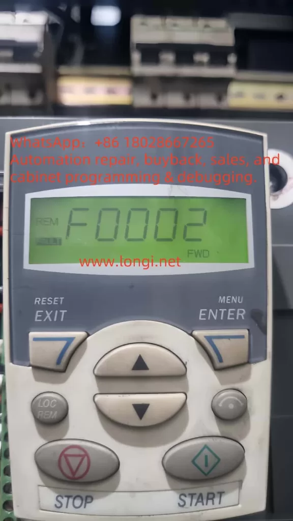
Within the ABB ACS550 series inverters, the F0002 fault code specifically indicates a DC bus overvoltage issue. When the inverter detects that the DC bus voltage exceeds its designed safety threshold, the control panel displays “F0002” or “OVERVOLTAGE” and triggers an automatic shutdown to protect the internal circuitry. This fault not only disrupts production but may also pose a risk of hardware damage, necessitating prompt diagnosis and resolution.
Analysis of Fault Causes
The F0002 fault stems from an abnormal rise in DC bus voltage, typically triggered by the following factors:
- Input Power Fluctuations
Transient or persistent voltage surges on the L1, L2, and L3 input power lines can cause the inverter’s rectifier circuit to pass excessive voltage to the DC bus, activating the overvoltage protection. - Excessive Regenerative Energy During Deceleration
If the deceleration time is set too short (e.g., parameters 2203 or 2206), the regenerative energy generated by the motor during deceleration cannot be dissipated promptly, leading to a rapid increase in DC bus voltage. - Inadequate Braking System Performance
In applications requiring frequent braking or involving high-inertia loads, insufficient capacity of the braking resistor or chopper may fail to absorb regenerative energy, causing voltage buildup. - External Load Feedback Energy
In specific scenarios (e.g., downhill conveyors or hoists), the motor may be driven by external forces, entering a generator state and feeding excess energy back to the inverter, resulting in an overvoltage fault.
These causes may occur individually or in combination, requiring a comprehensive approach to fault analysis.
On-Site Troubleshooting Steps
When encountering an F0002 fault, users can follow these steps to address the issue on-site and restore operation:
Step 1: Confirm the Fault and Shut Down
- Check the inverter display to verify the fault code as “F0002” or a prompt for “OVERVOLTAGE.”
- Immediately stop the inverter to prevent further escalation, ensuring safety for equipment and personnel.
Step 2: Inspect the Input Power
- Use a multimeter to measure the voltage across the L1, L2, and L3 input terminals to identify any anomalies.
- If power instability is detected, consider installing a voltage regulator or contacting the power supply provider for adjustments.
Step 3: Adjust Deceleration Parameters
- Access the parameter settings menu and review the deceleration time parameters (2203 or 2206).
- If the time is too short, extend it (e.g., from 5 seconds to 10 seconds) to reduce the accumulation rate of regenerative energy.
Step 4: Check the Braking System
- Verify that the braking resistor and chopper specifications match the load requirements.
- Inspect the braking resistor for signs of burning or disconnection, replacing it with a higher-power unit if necessary.
Step 5: Reset and Test
- After addressing potential issues, press the “RESET” button on the control panel to clear the fault.
- Restart the inverter and monitor its operating status to ensure the fault does not recur.
Step 6: Continuous Monitoring
- If the fault persists, record relevant operating data and consult a professional technician for further diagnosis.
These steps enable users to quickly pinpoint and resolve issues in the field.
Disassembly and Repair Process
If on-site troubleshooting fails to resolve the issue, disassembly and repair of the inverter may be required. The following is a detailed repair procedure:
1. Safety Preparation
- Disconnect the inverter power supply and wait at least 5 minutes to allow internal capacitors to fully discharge.
- Wear anti-static gloves to prevent damage to sensitive components.
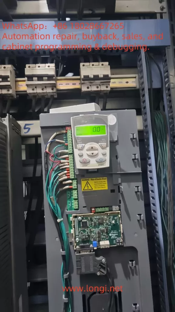
2. Visual Inspection
- Open the inverter casing and check the DC bus capacitors for swelling, leakage, or burn marks.
- Inspect the IGBT modules for signs of overheating or breakdown.
- If a braking resistor is installed, examine its surface for integrity.
3. Voltage Measurement
- With power applied (exercise caution), use a multimeter to measure the DC bus voltage, referencing the standard values in the ACS550 technical manual.
- Persistent high voltage may indicate issues with the capacitors or rectifier circuit.
4. Braking Circuit Testing
- Test the operation of the braking chopper to ensure proper switching functionality.
- Use an ohmmeter to measure the braking resistor’s resistance, confirming it matches the nominal value.
5. Control Circuit Troubleshooting
- Check the main control board’s circuit connections for short circuits or breaks.
- If equipped, use an oscilloscope to analyze the output signals of the voltage monitoring circuit.
6. Replace Damaged Components
- Based on inspection findings, replace damaged capacitors, IGBT modules, or braking resistors, preferably with ABB original parts.
- Ensure all connections are secure post-replacement to avoid poor contact.
7. Testing and Validation
- Reassemble the inverter and conduct no-load and load tests after powering on.
- Confirm that the fault code no longer appears and that operating parameters are normal.
Repair work should be performed by qualified personnel, adhering to safety standards. If unsure about specific steps, contact ABB technical support for assistance.
Preventive Measures and Recommendations
To minimize the occurrence of F0002 faults, users can adopt the following preventive measures:
- Regular Power Quality Checks: Ensure stable input voltage to avoid faults caused by grid fluctuations.
- Optimize Parameter Settings: Configure deceleration times based on load characteristics to prevent regenerative energy overload.
- Upgrade the Braking System: For high-inertia load applications, select braking resistors and choppers with adequate capacity.
- Routine Maintenance: Periodically clean dust from the inverter interior and inspect key components for signs of aging.
Conclusion
The F0002 fault in the ABB ACS550 inverter is a typical overvoltage issue, potentially arising from power anomalies, improper parameter settings, or inadequate braking. By following the on-site troubleshooting steps and repair procedures outlined in this article, users can systematically diagnose and resolve the problem. Additionally, implementing preventive measures can effectively reduce fault recurrence and extend equipment lifespan. This guide aims to provide practical reference material, supporting users in maintaining equipment and enhancing production efficiency.