
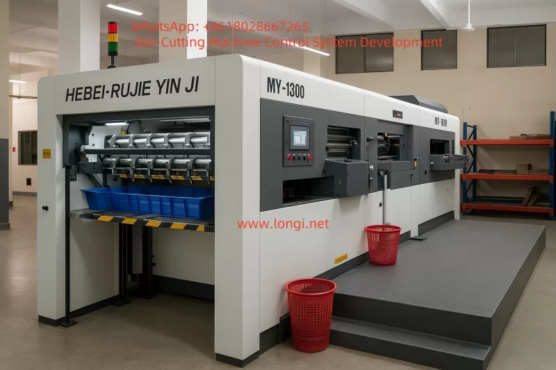
The Fully Automatic Platen Die-Cutting Machine is a specialized device designed for die-cutting and creasing/creasing of flat sheet materials such as cardboard, corrugated paper, and laminated paper. It integrates the traditional “hand press” platen principle with automatic paper feeding, positioning, collecting, fault detection, and safety interlock systems for batch production of color boxes, cartons, wine boxes, labels, hangtags, and some thin plastic packaging products.
I. Device Principle & Process Challenges
1.1 Basic Process of Platen Die-Cutting
Process Flow:
Paper Feeding → Positioning → Clamping & Conveying → Die-Cutting/Creasing → Waste Removal → Paper Collecting
Key Features & Challenges:
- High Inertia:
320-ton machine requires the crank-link mechanism to decelerate and stabilize near the top dead center. - Tight Timing Coupling Between Stations:
Intermittent transport of the gripper bar is synchronized with the die-cutting stroke; any timing deviation risks paper tearing.
1.2 Control Key Points & Challenges
| Key Points | Challenges | Solution Approach |
|---|---|---|
| Multi-Axis Synchronization (Feeder+Indexer+Platen) | Mechanical chain + intermittent cam cause rigid coupling; difficult to optimize speed curves. | Retain mechanical spindle; independent VFD speed control for Feeder. Gripper bar position identified via encoder Z-PULSE to avoid costly electronic cam reconstruction. |
| Registration & Repeatability | Paper stretching/static electricity, gripper bar spring fatigue. | Front/side guides + photoelectric correction; PLC checks X6/X7 every 10 ms, with high-speed interrupt correction. |
| Pressure Closed-Loop Control | 320-ton hydraulic cylinder pressure drift of 2%. | FX3U-4AD module for 4–20 mA signal; PID regulates Y12 pressure-building valve PWM. Set Press OK = 0.95 × Setpoint. |
| Safety Category 3 | Over 20 door switches + light curtains; often bypassed on older machines. | Pilz PNOZ X3 + safety relay dual-loop; real-time link status display on HMI. |
II. System Configuration Bill of Materials
| Category | Selection | Key Parameters/Quantity |
|---|---|---|
| PLC | Mitsubishi FX3U-80MT/ES-A | 80 I/O, transistor sink output; expansion modules: FX3U-4AD-PT-DA, FX3U-485-BD |
| HMI | Delta DOP-B10S411 (10.4″, 800×600) | COM1→PLC RS-422; COM2→VFD (Modbus-RTU) |
| VFD | Inovance MD200-11k-4 | Supports 0–10 V analog input + RS-485 monitoring |
| Servo Drive | Leadshine EL7-750 + 0.75 kW Motor | Indexer drive, 5000 ppr encoder |
| Safety | Pilz PNOZ X3 ×1, SICK Light Curtain ×2 | 2 N/C 2 N/O outputs, 24 V DC |
| Low-Voltage Distribution | Schneider NSX80N+GV2, Phoenix 24 V/10 A PSU | — |
| Sensors | Panasonic CX-400 Series Photoelectric (12), Ultrasonic Double-Sheet Detector ×1 | NPN output |
| Actuators | Airtac 4V210-08 Solenoid Valves (18), HYDAC Pressure Sensor 1.0–25 MPa | — |
Electrical Architecture Overview:
┌──── Pilz PNOZ ────► KM1 / KM3 / STO三相380 ▣ └─> MCB → VFD → Main Motor │ ┌─ Encoder ▼ ▼ PLC FX3U ──485─── MD200 (VFD) │RS-422 ▼ Delta HMI DOP-B10S411 │ ├── DO → Sol/Contactor └── AD → Press SensorIII. Control Logic & Program Architecture
3.1 Task Allocation
| Program Segment | Function | Key Components |
|---|---|---|
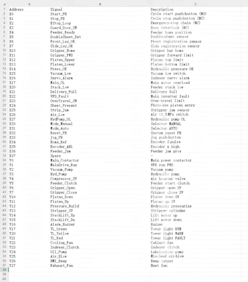
| P0 – Start/Emergency Stop | Main contactor, E-stop chain | X0, X1, X2 → Y0, Y1 |
| P1 – Paper Feeding & Registration | Feeder VFD, double-sheet detection, front/side guides | X4–X7, X35 → D400 PID, frequency control |
| P2 – Gripper Bar | Clamping cylinders, servo indexer | Y5, Y6, Y7, M404 interrupt |
| P3 – Die-Cutting | Platen servo, pressure closed-loop | Y10, Y11, Y12 → D410 PID |
| P4 – Paper Collecting | Lifting motor, counter | Y14, Y15, D200 piece counter |
| P5 – Alarm | Tower light, buzzer, HMI alarm codes | X16–X22, Y16, Y20, Y21 |
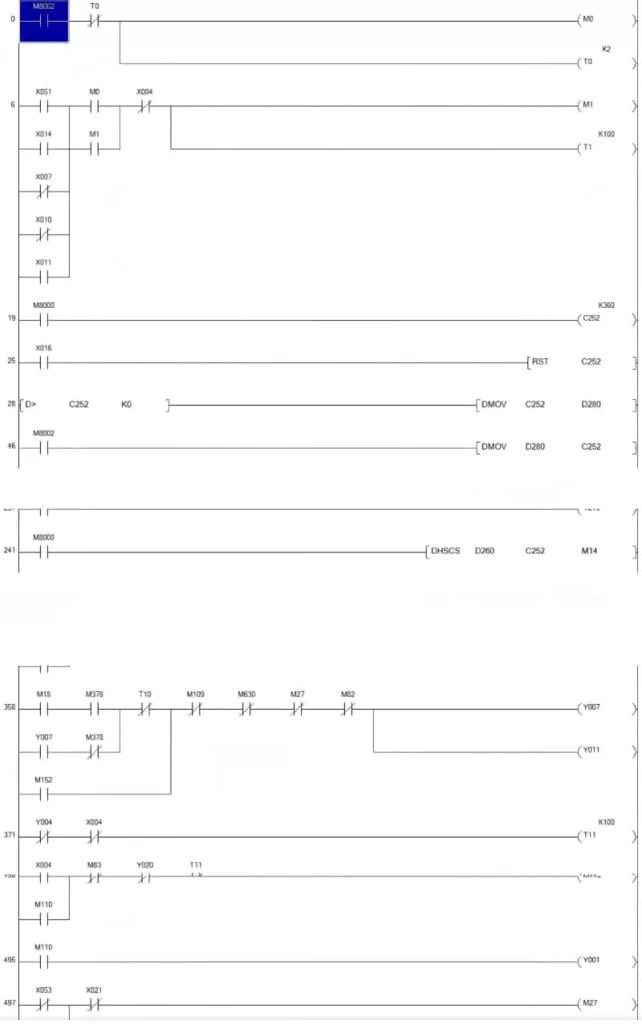
3.2 Main State Machine (S-Bits)
- S000 IDLE
- S010 FEED_READY
- S020 REGISTER
- S030 PRESS
- S040 DELIVERY
- S050 PAUSE / FULL
- S060 ALARM_STOP
All transition conditions are annotated in the CSV instruction list.
High-Speed Interrupt M8252 captures front-guide OK signal every 10 ms to set D404 for auxiliary correction.
3.3 HMI Screen Planning
| Screen No. | Theme | Key Objects/Components |
|---|---|---|
| 00 | Welcome / Machine Status Overview | Speed gauge, production count, current job |
| 01 | Auto Run | Start/Stop, speed setting, graphical timing bar |
| 02 | Settings | Front-guide fine-tuning (±0.1 mm), pressure setting (kN), batch stop count |
| 03 | Manual/Test Run | Jog buttons, I/O indicators, simulated teaching |
| 04 | Alarm | Alarm code, text description, handling guide |
| 05 | System | User permissions, I/O calibration, maintenance hours |
HMI Macro Example (Front-Guide Fine-Tuning):
; Macro No.11 Front-Guide +0.1 mmREADWORD d100, &H0004 ; Read current front-guide position from D100ADD d100, &H0001WRITEWORD d100, &H0004IV. I/O Allocation & Program Files
V. Enhancements & Future-Proofing
Electronic Cam Retrofit
- Replace mechanical spindle with servo + absolute encoder for virtual spindle + electronic scale registration to achieve speeds up to 5,500 sph.
MES Data Interface
- PLC reports production data to ERP via FX3U-ENET-AD module; add QR code scanning for job change on HMI.
Predictive Maintenance
- Connect key bearing and oil temperature sensors to FX3U-4AD; generate maintenance tasks automatically when runtime exceeds limits.
Safety Upgrade
- Replace single light curtains with SIL 2 extended versions for automatic restart inhibition; add safety STO (VFD) to E-stop.
Energy Recovery
- Retrofit main motor with torque-type servo + DC bus feedback for 8–12% energy savings.
VI. Project Implementation Milestones
| Period | Deliverables | Notes |
|---|---|---|
| T0+1 Week | Project Initiation & Electrical Scheme Confirmation | BOM, IO list v1.0 |
| T0+3 Weeks | Electrical Cabinet Drawings / PLC-HMI Program Alpha | CAD PDF + 80% program functionality |
| T0+5 Weeks | On-Site Assembly & Cold Commissioning | IO point-to-point, drive self-learning parameters |
| T0+6 Weeks | Hot Commissioning Trial Production (10 h) | Speed curve optimization, quality confirmation |
| T0+7 Weeks | FAT & Documentation Delivery | Chinese/English manuals, source code, backup images |
Key Takeaways Highlighted in Bold:
- Multi-Axis Synchronization: Mechanical spindle retained for cost efficiency; Feeder VFD and encoder Z-PULSE ensure precise gripper bar timing.
- Pressure Closed-Loop Control: PID-regulated hydraulic pressure for consistent die-cutting quality.
- Safety: Pilz PNOZ X3 + safety relay dual-loop prevents bypassing; real-time status display on HMI.
- Future-Proofing: Electronic cam, MES integration, predictive maintenance, safety upgrades, and energy recovery ensure long-term competitiveness.